

Thread
Mac SE/30 with strange SimasiMac - help needed
Hi,
I acquired an SE/30 some time ago and it worked but started to show first symptoms of SimasiMac. Some weeks ago I gave it to a friend who has good soldering skills to do the recap. I gave him just the mainboard with everything removed.
When I got the board back and installed it, the SE/30 greeted me with this SimasiMac "on steroids":
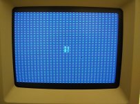
The Mac shows the mouse pointer, I can move it and it shows the flashing "give me a boot disk" question mark. The pattern looks like a combination of the jail bar pattern and a checkered flag.
I decided to replace all caps again (this time I used tantalums, except from the big axial types of course). I recognized that my friend had ripped one the pad of C6 (plus side). I connected the plus side of the cap with pin 7 of chip UB11 with a wire. Still I got the same symptoms.
I then thoroughly washed the board and inspected all chips for blobs of solder and reseated the ROM chips and RAM. No change. I visually checked the underside of the board: all clean and well. I tested all caps for correct connection to ground or the respective other parts of the board. Everything seems normal apart from C1 where my multi meter shows a resistance of 500 ohms on both pins (to ground and Pin 12 of J12). I used the replacement and pinout jpeg posted on this board and Apple's schematics as a reference.
So now I'd like to ask the experts if they recognize this kind of SimasiMac. What is the cure or what can I do to further diagnose the problem? I have a scope and multi meter.
Any help is much apreciated.
Best, bobo68
I acquired an SE/30 some time ago and it worked but started to show first symptoms of SimasiMac. Some weeks ago I gave it to a friend who has good soldering skills to do the recap. I gave him just the mainboard with everything removed.
When I got the board back and installed it, the SE/30 greeted me with this SimasiMac "on steroids":
The Mac shows the mouse pointer, I can move it and it shows the flashing "give me a boot disk" question mark. The pattern looks like a combination of the jail bar pattern and a checkered flag.
I decided to replace all caps again (this time I used tantalums, except from the big axial types of course). I recognized that my friend had ripped one the pad of C6 (plus side). I connected the plus side of the cap with pin 7 of chip UB11 with a wire. Still I got the same symptoms.
I then thoroughly washed the board and inspected all chips for blobs of solder and reseated the ROM chips and RAM. No change. I visually checked the underside of the board: all clean and well. I tested all caps for correct connection to ground or the respective other parts of the board. Everything seems normal apart from C1 where my multi meter shows a resistance of 500 ohms on both pins (to ground and Pin 12 of J12). I used the replacement and pinout jpeg posted on this board and Apple's schematics as a reference.
So now I'd like to ask the experts if they recognize this kind of SimasiMac. What is the cure or what can I do to further diagnose the problem? I have a scope and multi meter.
Any help is much apreciated.
Best, bobo68
your problem is going to be in this area some where.
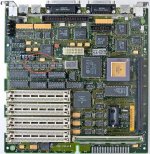
in the from of something rotted from cap goo.
- trace
- via
- Pad I/c is connected to
- something under one of the I/C's
in the from of something rotted from cap goo.
- trace
- via
- Pad I/c is connected to
- something under one of the I/C's
Ok, will have a closer look. I forgot to mention that the startup sound is also distorted.
****
also read this thread. https://68kmla.org/forums/index.php?/topic/20541-se30-horizontal-sweep-linesstill/page-3
also read this thread. https://68kmla.org/forums/index.php?/topic/20541-se30-horizontal-sweep-linesstill/page-3
Sound being distorted is probably something under the ASC. Witch is right there near that red circle in the image.
cap goo likes to creep under I/C's and rot. it's unpleasant really.
cap goo likes to creep under I/C's and rot. it's unpleasant really.
Where is the ASC relative to C7 on your picture?
I thoroughly cleaned the board with isopropanol and later also water + dishwasher (and let it dry). Do you think there can still be some goo left?
I thoroughly cleaned the board with isopropanol and later also water + dishwasher (and let it dry). Do you think there can still be some goo left?
( and let it dry ) --
i would make it dry with an air compressor.
blast all the water out of all the nooks and crannies.
the issue right now, is past shorting from cap goo,
the issue right now is damage that has been done from the cap goo.
so its going to require some repair at this point, by running patch wires, more then likely.
ASC is in yellow
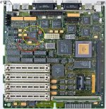
i would make it dry with an air compressor.
blast all the water out of all the nooks and crannies.
the issue right now, is past shorting from cap goo,
the issue right now is damage that has been done from the cap goo.
so its going to require some repair at this point, by running patch wires, more then likely.
ASC is in yellow
If the sound is distorted, you have a broken data/address line, which probably also feeds the video circuitry which is right there.
So, you need to grab the SE/30 schematics, and test ALL address/data lines from that IC, against the ROM socket. The break is likely right above the power jack below the SCSI/SCC
So, you need to grab the SE/30 schematics, and test ALL address/data lines from that IC, against the ROM socket. The break is likely right above the power jack below the SCSI/SCC
Hi techknight,
just to be absolutely sure: what do you mean with "that IC" and "ROM socket"? The ASC and the ROM SIMM?
Best, bobo68
just to be absolutely sure: what do you mean with "that IC" and "ROM socket"? The ASC and the ROM SIMM?
Best, bobo68
I did some connection testing in the areas you mentioned. Not completely but like in thread https://68kmla.org/forums/index.php?/topic/20541-se30-horizontal-sweep-linesstill/page-3 I found that A0 line between UD8 and UK6 (Video ROM) has no connection. The Oother address lines from UD8 and UE8 do connect to UK6.
Furthermore I tried other A0 connections and found them also to be broken between UI8 (GLUE) and UE10 (ASC). A1 is connected. Same between UD8 and UI8 (A0 broken, A1 ok).
Is this a pattern you recognize? Maybe there is a central point where it should be fixed.
Furthermore I tried other A0 connections and found them also to be broken between UI8 (GLUE) and UE10 (ASC). A1 is connected. Same between UD8 and UI8 (A0 broken, A1 ok).
Is this a pattern you recognize? Maybe there is a central point where it should be fixed.
Follow the schematic, if theres a break where there should be a connection, run a patch wire and test again.
Sure I can do it the pedestrian way. I was hoping somebody has seen this combination of video and audio failure and there is a central point where it can be fixed.
I have a hard time understanding how the connections run across the 9 pages of the schematic. I cannot find any markers which allow me to stitch together the whole schematic.
That said, is e.g. an address line supposed to be connected across the whole board? e.g. A1 can be found on many chips, do they all directly connect or is there an intermediary between them (the GLUE?)?
Where are lines VADR supposed to go? They can be found on UA8, etc.
I have a hard time understanding how the connections run across the 9 pages of the schematic. I cannot find any markers which allow me to stitch together the whole schematic.
That said, is e.g. an address line supposed to be connected across the whole board? e.g. A1 can be found on many chips, do they all directly connect or is there an intermediary between them (the GLUE?)?
Where are lines VADR
supposed to go? They can be found on UA8, etc.
A0/A1 is only located on a few chips. Most of the bus starts at A2+
Ok. Connecting the A0 address line between UD8 and UK6 brought the video back without any jail bars etc. Woohoo. Now comes the sound...
I figured it would 
Do you know if UE10 (ASC) should be directly connected to UI8 (GLUE)? I can see a trace between them that looks super good but still no connection on the A0 line.
Or should I go from UE10 to UK6 (Video ROM)?
Or should I go from UE10 to UK6 (Video ROM)?
I believe it does go to the GLU. But I cant remember. If the schematic shows there is an A0 present, then its likely broken.
I decided to connect UE10 and UI8 directly. It worked, the little sucker now has video and sound. Nice! Thanks for your support.
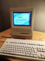
So this one will get an Ethernet card as an award later and I have another SE/30 waiting for the recap. And a IIci.
So this one will get an Ethernet card as an award later and I have another SE/30 waiting for the recap.
And a IIci.
Nice work!
Nice work!
Sweet! Back from the grave, good job!
so just to help out future people, you ran a wire from
ASC pin 41
to
GLU pin 77
looks like if that one goes, then so could this one too.
GLU pin 74
to
ASC pin 42
Whenever I get scratchy sound, I always take ASC off, scrub the pads really good with flux and wick,
Sometimes i will scrap the SM a little from the pad if i see some rot.. just to make sure there is a good connection between the pad and the trace.
flood all the pads with solder and flow the chip back on and most of the time that fixes fizzy sounds issues.
ASC pin 41
to
GLU pin 77
looks like if that one goes, then so could this one too.
GLU pin 74
to
ASC pin 42
Whenever I get scratchy sound, I always take ASC off, scrub the pads really good with flux and wick,
Sometimes i will scrap the SM a little from the pad if i see some rot.. just to make sure there is a good connection between the pad and the trace.
flood all the pads with solder and flow the chip back on and most of the time that fixes fizzy sounds issues.
Yes, I ran a wire from ASC pin 41 to GLUE pin 77 (the A0 address line). I'm relatively sure that the failure of this line can be attributed to the ASC's pin/pad because the trace on the board to the GLUE is short and looks very good.
A1 (pin 42 ASC to pin 74 GLUE ) was still intact. I did not want to resolder the ASC because my SMD skills are limited. I'm actually quite proud to have soldered in the small tantalum SMD capacitors and the wires. We'll see if the cleaning was enough to stop A1 from failing.
On top of that I connected UD8 pin 4 to UK6 (Video ROM) pin 10 which brought video back to normal. And I had to connect the plus side of C6 to UB11 (Sony sound chip) pin 7 because the plus side pad of C6 was gone.
A1 (pin 42 ASC to pin 74 GLUE ) was still intact. I did not want to resolder the ASC because my SMD skills are limited. I'm actually quite proud to have soldered in the small tantalum SMD capacitors and the wires.
We'll see if the cleaning was enough to stop A1 from failing.On top of that I connected UD8 pin 4 to UK6 (Video ROM) pin 10 which brought video back to normal. And I had to connect the plus side of C6 to UB11 (Sony sound chip) pin 7 because the plus side pad of C6 was gone.
So in short 68kmla helped save the day, another happy Mac back in service, successfully liberated.
So just a1 and a0 go to the glue, The other address lines to the ASC could also cause scratchy sound... But those lines would need to be ran from other I/C's... What ones look like a safe bet? looks like those other address lines connect up all over the place.... A2+> etc. I ask because I am building documentation for shot gun fixes for the se/30. I mean cap goo can really only cause so much rot, in only so many places.
So just a1 and a0 go to the glue, The other address lines to the ASC could also cause scratchy sound... But those lines would need to be ran from other I/C's... What ones look like a safe bet? looks like those other address lines connect up all over the place.... A2+> etc. I ask because I am building documentation for shot gun fixes for the se/30. I mean cap goo can really only cause so much rot, in only so many places.
Right now I am mastering the art of flux less solder fixes, pad to trace, solder most of the time has an undesirable trate of not flowing with out flux, well if you are careful this can be a good thing when fixing bad pad trace connections under the IC. . It's defiantly something that takes some practice that's for sure, Just the slight bit of flux and your connection is now lost.
. It's defiantly something that takes some practice that's for sure, Just the slight bit of flux and your connection is now lost.I can't tell from the schematics. GLUE and ASC are not on the same page of the multi-page document so it is not clear where the traces run exactly.
ASC has A0 - A11, GLUE has A0, A1 and then from A13 onwards (but not all lines, e.g. A18 is missing).
Furthermore ASC's A1 and A2 seem to go directly to UG12 (8530 SCC).