

Thread
Compact Mac Power Meter Tool. :-)
i had the need for one, so i made one.


Looks good, but IMO you should have used a red voltmeter for the -12V line 
That is so cool! Would be handy for the 40+ compacts I have to get running.
I love gizmos, especially gizmos with blinkenlights and LCDs. 
Sweet. And elegant.
lol lameboy.
Yeah you are right.. i got these for 99 cents free shipping.
The auction was for green only... i bought these to connect up to all my radios, (ham) equipment.
- So i could see the drop when i key up.
It looks like on ebay for a little more you have a choice of LED colors!
Those volt meters are super glued to that plastic piece, that plastic piece if from an anti static I/C tube.
and then the over sized shrink tube is from harbor freight.
The volt meters are good from 1-30 vdc, the meter needs at least 3 volts to run though.
http://www.ebay.com/itm/New-Firm-0-30V-Red-Blue-0-32V-Yellow-LED-Digital-Voltage-Voltmeter-Motorcycle-/291223614696?pt=LH_DefaultDomain_0&var=&hash=item43ce47b4e8
These meters are a little more... and a little more fancy. $1.27 free shipping
Yeah you are right.. i got these for 99 cents free shipping.
The auction was for green only... i bought these to connect up to all my radios, (ham) equipment.
- So i could see the drop when i key up.
It looks like on ebay for a little more you have a choice of LED colors!
Those volt meters are super glued to that plastic piece, that plastic piece if from an anti static I/C tube.
and then the over sized shrink tube is from harbor freight.
The volt meters are good from 1-30 vdc, the meter needs at least 3 volts to run though.
http://www.ebay.com/itm/New-Firm-0-30V-Red-Blue-0-32V-Yellow-LED-Digital-Voltage-Voltmeter-Motorcycle-/291223614696?pt=LH_DefaultDomain_0&var=&hash=item43ce47b4e8
These meters are a little more... and a little more fancy. $1.27 free shipping
here is a basic pinout, incase someone wants to wire one up for them selves.
. 1 CGND Chassis ground
. 2 CGND Chassis ground
. 3 CGND Chassis ground
. 4 CGND Chassis ground
. 5 -12V
. 6 +5V
. 7 +12V
. 8 +12V
. 9 N/C Not connected
. 10 PWM Regulates speed of the drive
. 11 PH0 Control line to send commands to drive
. 12 PH1 Control line to send commands to drive
. 13 PH2 Control line to send commands to drive
. 14 PH3 Control line to send commands to drive
. 15 WrReq- Turns on the ability to write data to the drive
. 16 HdSel Control line to send commands to the drive
. 17 Enbl2- Enables the Rd line (else Rd is tristated)
. 18 Rd Data actually read from the drive
. 19 Wr Data actually written to the drive
. 1 CGND Chassis ground
. 2 CGND Chassis ground
. 3 CGND Chassis ground
. 4 CGND Chassis ground
. 5 -12V
. 6 +5V
. 7 +12V
. 8 +12V
. 9 N/C Not connected
. 10 PWM Regulates speed of the drive
. 11 PH0 Control line to send commands to drive
. 12 PH1 Control line to send commands to drive
. 13 PH2 Control line to send commands to drive
. 14 PH3 Control line to send commands to drive
. 15 WrReq- Turns on the ability to write data to the drive
. 16 HdSel Control line to send commands to the drive
. 17 Enbl2- Enables the Rd line (else Rd is tristated)
. 18 Rd Data actually read from the drive
. 19 Wr Data actually written to the drive
The variety of cheap assemblies available on Ebay is wonderful. When I considered replacing the guts of an MDD power supply with the guts of an ATX, I gave thought to the 28V supply line. A quick check on Ebay and there are variable output DC-DC boost circuits available that would work nicely for both the 5V standby line and the 12V regular line and all for a couple of bucks.
Gotta watch out for cheap power supplies though. They tend to go erratic, or throw out noise and unstable voltages.
In most cases though they are fine, but you do have to watch out fo rthat.
In most cases though they are fine, but you do have to watch out fo rthat.

this LACK of DB19 Male Connectors, Steve(BMOW) is experiencing has me thinking of other ways to connect something to the DB19 floppy port of the mac.
so in my experimenting i removed a DB19 connector from a dead main board. And decided to clip chunks of 2's off my header here.
its funny how as 2's they line up diagonally perfectly, then just a little bit of trimming for the final single pin, pin 10
so i pop all these into the female DB19, and put some super glue on the outside of them all, so they lock in as one connector.
Then I let that fan cure. Next, Soldered on the wires and used some better rubberized adhesive GOOP on the pins and such, next shrink tubed over that.
Haven't tested it yet i'm letting the GOOP set up… but i think it should work good.
at-least for this use… not sure about floppy emu use… but maybe if we get desperate enough… it should probably work as long as one doesnt
get too messy with the super glue.
Mechanically it fits into the connector nice and snug, feels like the female connector that would be on the main board has a nice bite on it.


so in my experimenting i removed a DB19 connector from a dead main board. And decided to clip chunks of 2's off my header here.
its funny how as 2's they line up diagonally perfectly, then just a little bit of trimming for the final single pin, pin 10
so i pop all these into the female DB19, and put some super glue on the outside of them all, so they lock in as one connector.
Then I let that fan cure. Next, Soldered on the wires and used some better rubberized adhesive GOOP on the pins and such, next shrink tubed over that.
Haven't tested it yet i'm letting the GOOP set up… but i think it should work good.
at-least for this use… not sure about floppy emu use… but maybe if we get desperate enough… it should probably work as long as one doesnt
get too messy with the super glue.
Mechanically it fits into the connector nice and snug, feels like the female connector that would be on the main board has a nice bite on it.
Very interesting approach! The spacing is a little bit off there, but the pairs of pins probably bend slightly, which helps give a more snug fit. Standard headers are 2.54 mm spacing, the pins in each DB-19 row at 2.77 mm, rows are 2.84 mm apart, and the diagonal you're using is 3.16 mm.
The concern I would have is that you're putting a square peg in a round hole. Literally. The 0.1" header pins are square, and the holes inside the DB-19 connector are round, so there will only be electrical contact at the outside corners of the square pins. That may create a high resistance connection, or a flakey connection. Or maybe it would work fine.
If this works, to make them in large quantities you could probably replace the super glue, GOOP, and heat shrink with a tiny circuit board.
The concern I would have is that you're putting a square peg in a round hole.
Literally. The 0.1" header pins are square, and the holes inside the DB-19 connector are round, so there will only be electrical contact at the outside corners of the square pins. That may create a high resistance connection, or a flakey connection. Or maybe it would work fine. If this works, to make them in large quantities you could probably replace the super glue, GOOP, and heat shrink with a tiny circuit board.
The ones I was looking at appear to be based on standard National Semiconductor controllers using reference designs. Of course, the NS controllers could be counterfeit...
I've used DC-DC reducing (buck?) controllers I bought for a dollar or two and the power appears stable so far. No protection designed in for overload though.
Have you folks tried here:
http://www.iec-usa.com/cgi-bin/iec/05MPartDB19.html
which I mentioned in this thread:
https://68kmla.org/forums/index.php?/topic/15781-found-source-for-19-pin-connectors/&do=findComment&comment=156862
I've never actually tried ordering from them, and some places turn out to be permanently out of stock even though their ordering page looks promising, but it's probably worth a try.
Steve bought out IECs supply.
heck yeah, on the pcb steve.
I guess i'm a square peg in a round hole kinda guy...
I chuckled last night when i realized the same thing.
let me say that at least for my application it does work...
the plug i made does naturally seem to pop on pretty smoothly.
and it stays in.
so i was thinking i could also just use 2 single inline headers one for the bottom one for the top.
then just use 2 little drops of super glue to bond that together.
solder the wires, then apply some 5 minute epoxy, then shrink tube over that.
maybe your next pcb run you could experiment with a little pcb with a DB20 male on it for the floppy emu.
and then we can do some real world testing for the floppy emu. I don't think you are going to have any resistance issues.
and the power draw of your device is so little there will not be a amperage issue considering the square edges are making the contact
instead of a round edge.
or maybe do an angled db20 connection then the floppy emu could plug in and be 90 degree? as well
and like i said just use 2 rows of single inline. one 10 pins one 9 pins and solder then to your pcb.
I guess i'm a square peg in a round hole kinda guy...
I chuckled last night when i realized the same thing.
let me say that at least for my application it does work...
the plug i made does naturally seem to pop on pretty smoothly.
and it stays in.
so i was thinking i could also just use 2 single inline headers one for the bottom one for the top.
then just use 2 little drops of super glue to bond that together.
solder the wires, then apply some 5 minute epoxy, then shrink tube over that.
maybe your next pcb run you could experiment with a little pcb with a DB20 male on it for the floppy emu.
and then we can do some real world testing for the floppy emu. I don't think you are going to have any resistance issues.
and the power draw of your device is so little there will not be a amperage issue considering the square edges are making the contact
instead of a round edge.
or maybe do an angled db20 connection then the floppy emu could plug in and be 90 degree? as well
and like i said just use 2 rows of single inline. one 10 pins one 9 pins and solder then to your pcb.
I read somewhere of people taking db-25 connectors and cutting off the excess, perhaps not the neatest solution (so it's probably no good for the floppy emu) but it should work fine for things like this
Would two rows of 0.1" single header fit? The spacing looks too far off to me. Your diagonal trick works well, but you have to do 9 pairs of 2 pins each on the diagonal, plus a spare.
You could test your square peg / round hole question by putting a dummy load on the supply. Maybe try four 100 ohm 1/4 watt resistors and put them all in parallel between +5 and GND. That would be 25 ohm, 200 mA, 1 watt total (the resistors will get hot). Then see if the 5V supply drops noticeably, as measured by your power meter. If not, then the square peg / round hole is probably fine.
You could test your square peg / round hole question by putting a dummy load on the supply. Maybe try four 100 ohm 1/4 watt resistors and put them all in parallel between +5 and GND. That would be 25 ohm, 200 mA, 1 watt total (the resistors will get hot). Then see if the 5V supply drops noticeably, as measured by your power meter. If not, then the square peg / round hole is probably fine.
i used (3) 54 ohm resistors in parallel and got a .8-9 voltage drop @ 5v
Thanks for trying it out! So my math says that's 18 ohms, which should draw 277 mA from the supply assuming everything else is zero resistance. You're seeing a drop to 4.1 - 4.2V? That's pretty significant, although 277 mA is a bigger load then you're likely to see in reality (I think Floppy Emu is like 150 mA). Does it change if you wiggle the connector around, to get more contact between the corner of that square pin and the round socket?
let me do it one more time… i want to make sure i am not a decimal place off.
ok i did it again
with out resistors… 5.0
with resistor 4.9
so pretty sure that is .09 of a drop… sorry about the confusion.
the multimeter was reading 4.99
LOL so i just did the same test with the last extra db19 connector and i got
4.80 , granted the connector pins might have flux on them.. etc..
i am going to do a video.
Stand by…
the header holds in there nice.. its snug… i wiggle it… its solid across all 3 meters.. no jittery numbers or anything.
with out resistors… 5.0
with resistor 4.9
so pretty sure that is .09 of a drop… sorry about the confusion.
the multimeter was reading 4.99
LOL so i just did the same test with the last extra db19 connector and i got
4.80 , granted the connector pins might have flux on them.. etc..
i am going to do a video.
Stand by…
the header holds in there nice.. its snug… i wiggle it… its solid across all 3 meters.. no jittery numbers or anything.
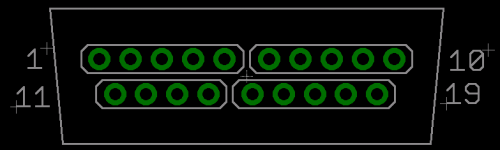
I've been experimenting with your substitute DB19, built from 9 1/2 pairs of angled 2-pin 0.1" header. I think I have a slightly improved solution: 3 straight 5-pin 0.1" headers and 1 straight 4-pin 0.1" header. The spacing between holes on the DB19 isn't 0.1", so it's not quite the right fit, and a 9- or 10-pin header strip won't go in. But if you use 4- or 5-pin strips, the pins have enough bend to them that they'll fit snugly.
One drawback is that without the surrounding flange (is that the right word?), it's possible to insert the connector so that the whole thing is offset 1 position left or right. That would be instant death for any sensitive electronics that suddenly got +12V. I wonder if there's a way to build enough of a poor-man's flange to prevent that from happening.
Like this:
I wonder if you could design "the shield" as plastic in a printed/molded case? Because then you can solder the pins in place on the PCB, and when the housing is snapped together, everything aligns on the DB19.
that is a great idea mike!
A plastic shield would be great, but I don't know where or how you'd get those made cheaply and in small quantities. 3D printing is cool for novelties, but probably too slow and expensive for something like this. Any suggestions for a source?
I was thinking maybe there's some common electronic parts that I could throw on there, to function like a shield, even if they didn't do anything electrically. Randomly searching Digikey for parts that are tall, thin, and cheap. Some kind of rail or tab or something maybe...
I was thinking maybe there's some common electronic parts that I could throw on there, to function like a shield, even if they didn't do anything electrically. Randomly searching Digikey for parts that are tall, thin, and cheap.
Some kind of rail or tab or something maybe...
did you call up foxconn in china and ask them to make you some db19 connectors?
maybe have em make you like up like 5000 or something, then you can be the world master distributor of them
they probably still have the Die's in a file cabinet somewhere.
maybe have em make you like up like 5000 or something, then you can be the world master distributor of them
they probably still have the Die's in a file cabinet somewhere.