

That is great!, thanks!
the best thing you could do is to make a table showing which pin of the Logic board adapter plug (the blue bit that goes from the white flat cable to the orange cable, first pic below) goes to which pin of the display (second pic below, the empty CN1).
before making the replacement cable, I took a photo of that plug and tired to match each of the "joints" with the corresponding number on the display (i wrote them on the silver solder joints). I think I did a mistake somewhere, but without a working cable I'm stuck.
right now I only need the video data, backlight should be easier.
essentially a table showing the connection from here
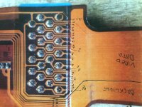
to here, CN1
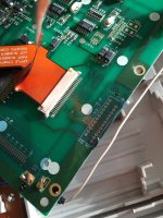
the best thing you could do is to make a table showing which pin of the Logic board adapter plug (the blue bit that goes from the white flat cable to the orange cable, first pic below) goes to which pin of the display (second pic below, the empty CN1).
before making the replacement cable, I took a photo of that plug and tired to match each of the "joints" with the corresponding number on the display (i wrote them on the silver solder joints). I think I did a mistake somewhere, but without a working cable I'm stuck.
right now I only need the video data, backlight should be easier.
essentially a table showing the connection from here
to here, CN1