

Thread
Another crazy portable hack of mine
Well, Here I am. Up to no good again.
Can you see what I am doing so far?
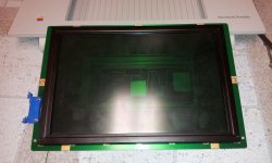
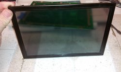
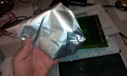
Can you see what I am doing so far?
Either you are going transparent, or you will be installing an "indeglo" EL sheet - which would be cool 
You're disassembling a perfectly fine Portable LCD?
c
c
BACK LIGHT!!!!! to the NON BACK LIT!! LOL WOOOOOOOOOOOOOOOOO! 
Uniserver nailed it!
I have an extra one of these displays so I dont care if I kill it or not. Chalk it up to scientific research. hahah...
I am thinking about going with an EL sheet, A5 size is a bit too small especially given the electrode sizes on the boarder.
So I am going to look for an A4 sheet and cut it down. But I need to find out if they are cuttable, and they are a bit pricey! If I can cut the material down, I do have to leave the electrode in place at least on 1 of the edges. So, most likely i will compensate for that, and just fold the electrode underneath so its not blocking visible areas.
The visible area of the LCD panel is roughly 216MM x 140MM. Just under the A5 sheet size. at least horizontally.
I havent decided on color. Maybe aqua blue? or white? I dunno.
but... There is the matter of getting the "wires" out of the panel. the Zebra stripe LCD connector strips run around all 4 sides. so... I am either going to have to fit HV wire in between in the corners, or drill holes in the PCB in unused areas. Traces are everywhere and spacing is really tight... but I think I can find a remote location and drill a hole. But I have to keep the creepage distance to a minimum, because the first arc-over from HV to signal trace = BANG. goodbye LCD.
I have an extra one of these displays so I dont care if I kill it or not. Chalk it up to scientific research. hahah...
I am thinking about going with an EL sheet, A5 size is a bit too small especially given the electrode sizes on the boarder.
So I am going to look for an A4 sheet and cut it down. But I need to find out if they are cuttable, and they are a bit pricey! If I can cut the material down, I do have to leave the electrode in place at least on 1 of the edges. So, most likely i will compensate for that, and just fold the electrode underneath so its not blocking visible areas.
The visible area of the LCD panel is roughly 216MM x 140MM. Just under the A5 sheet size. at least horizontally.
I havent decided on color. Maybe aqua blue? or white? I dunno.
but... There is the matter of getting the "wires" out of the panel. the Zebra stripe LCD connector strips run around all 4 sides. so... I am either going to have to fit HV wire in between in the corners, or drill holes in the PCB in unused areas. Traces are everywhere and spacing is really tight... but I think I can find a remote location and drill a hole. But I have to keep the creepage distance to a minimum, because the first arc-over from HV to signal trace = BANG. goodbye LCD.
I'd look for the most power efficient color, that's also still usable.
Powering the EL sheet is definitely doing to be an interesting experience. I may have to roll my own inverter. Not sure yet.
12V inverters are kind of big on power consumption, so the internal 12V regulator on the logic board will not suffice. the 5V inverters on the market dont have enough output current to run a large A5+ sheet.
So, I think i will use a regulated output inverter off the main 6 to 7.5V B supply. The voltage is relatively low. 100 to 200v. at rouhgly 400Hz. Easily doable with a re-wound CCFL transformer, and a 555 timer circuit.
I thought about LEDs, and laser etched gradation sheet (used in modern day LED panels), but not enough room underneath to put it.
12V inverters are kind of big on power consumption, so the internal 12V regulator on the logic board will not suffice. the 5V inverters on the market dont have enough output current to run a large A5+ sheet.
So, I think i will use a regulated output inverter off the main 6 to 7.5V B supply. The voltage is relatively low. 100 to 200v. at rouhgly 400Hz. Easily doable with a re-wound CCFL transformer, and a 555 timer circuit.
I thought about LEDs, and laser etched gradation sheet (used in modern day LED panels), but not enough room underneath to put it.
I wish I would have thought of an EL sheet  lol
lol
lol
hey that stuff is pretty cool!

Yup. its going to be fun to get it in there because of all 4 sides of the panel being used for electrical connections.
But ill figure out a way.
But ill figure out a way.
Certainly one of the coolest hacks. I'm looking forward to it.
This is going to be interesting!
Technight. I have a spare non back-lit display you can have if you want it. The LCD part is damaged from heat or pressure. So that part is no good. But for practice/parts it probably is fine.
would be great if you can figure out a straight forward process.
maybe ones could send you their screen!? for a price.
maybe ones could send you their screen!? for a price.
Well I ordered the A4 sheet. Expensive, but at least it comes with the inverter and wiring.
So, The seller did say I can cut down the sheet, and fold over the electrode, and it would work fine. So we will see....
As far as wiring the inverter into the portable, I have yet to figure out how I am going to do that. I think I will pick off the system standby signal from the PMU IC (yes, I know which pins those are, haha).
Once I have that, I can then allow the inverter to be switched on or off depending on whether the machine is in standby or powered on.
As far as electronic brightness control from the OS, Well thats not possible unless I develop my own little hardware with a custom control panel that speaks to it, Or.. if someone would graciously let me "borrow" a 5120 to 5126 apple backlit conversion portable/kit.
This would allow me to reverse engineer the control logic they created, and I can adapt it over to EL/LED. No issue.
So, The seller did say I can cut down the sheet, and fold over the electrode, and it would work fine. So we will see....
As far as wiring the inverter into the portable, I have yet to figure out how I am going to do that. I think I will pick off the system standby signal from the PMU IC (yes, I know which pins those are, haha).
Once I have that, I can then allow the inverter to be switched on or off depending on whether the machine is in standby or powered on.
As far as electronic brightness control from the OS, Well thats not possible unless I develop my own little hardware with a custom control panel that speaks to it, Or.. if someone would graciously let me "borrow" a 5120 to 5126 apple backlit conversion portable/kit.
This would allow me to reverse engineer the control logic they created, and I can adapt it over to EL/LED. No issue.
Ya, the sheets can be cut. Seems weird, but they can. I used to play with EL sheets long, long ago.
My EL sheet was shipped out today.
So hopefully I dont botch this 60 odd dollar EL sheet while cutting it.
So hopefully I dont botch this 60 odd dollar EL sheet while cutting it.
Major updates on this front. Wowee what a nightmare.... began to question myself a bit. But I am the mad scientist after all..
Ill post further details with lots of pictures a bit later when I get off work.
Ill post further details with lots of pictures a bit later when I get off work.
Ok, Got my A4 EL sheet in today.
Here is what it looks like behind the screen powered-off:
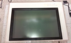
And with it on:
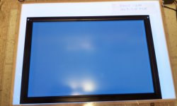
I asked him to send Aqua, but he was out of stock so I ended up getting light blue. So not quite Indiglo. But close enough. I think it looks cool regardless.
With that out of the way, Its time to figure out how to cut this thing down to size, and get it to fit between the panel and the driver electronics. Not an easy task. Considering I need to pick it right the first time, as i dont want to kill this $60 sheet of A4 EL stuff.... Also the inverter is HUGE. I still havent figured out what to do about that, yet...
Here is the electrodes on the panel itself:
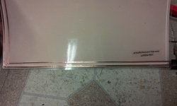
Also, Here is the electrode connections from the inverter, Clearly sticking out from the edge of the EL sheet. This wasnt going to work, for one its too thick so I Cant fold it back, and have enough room to put it back together. It just had to go.
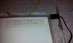
If I cut that out, Then what can I do about it? Well I can scratch through the laminate on the backside of course! This allowed me to reconnect the electrode wires from the inverter.
So, after some careful cutting, you end up with this:
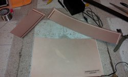
Now, that leaves just the top electrode to deal with. What to do about that? Well fold it out of the way behind it! Well, this is ok, but you have to make sure the fold is just before, or on the edge of the visible area. Folding the EL sheet in a visible area, can cause delamination or electrode distortion, killing the light in that section. Keep this in mind.
Here is the folded electrode, you can just see it sticking up:
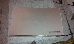
Here is the backside mount of the original wires:
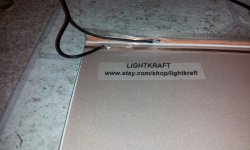
Test fit:
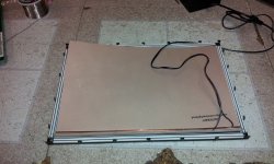
And lets light it up!
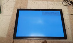
So, now its time to get it back into the LCD assembly. Well, this is where I ran into yet another problem: The original electrode wires were too thick! Well, I had to cut away some of the top folded plastic, I also had to cut back a tiny bit of the Zebra strip (conductive rubber between LCD glass and PCB). And solder in some 30 gauge wire. This is very thin wire, But its thin enough JUST to fit... Luckily its not causing any problems, because the inverter carries anywhere from 90 to 150VAC.
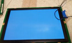
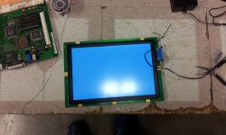
Here is a picture of it off. Yes you can still use it without the backlight on
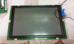
Now another problem: I had to make a new LCD ribbon cable between the motherboard and the LCD. The one I had, someone pretty much screwed it, scraped it, severing some wires. So, I decided to grab an old U-ATA133 IDE Ribbon, and make up a new one:
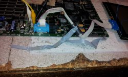
And Here are the results:
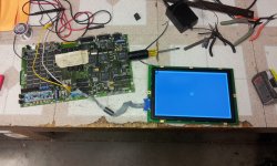
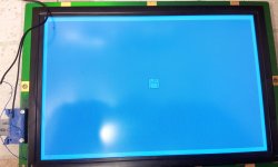
It works... YAY!!!!
Still more to do, Figuring out where to mount the inverter, And see if I can coax bbraun to make me a small control panel enable/disable the backlight and brightness.
The inverter pulls 560Ma at full brightness. This drops substantially when you slowly bring the voltage down to the inverter.
I will likely make a small decoder/driver card that goes into the ROM slot for the control panel in system 6/7 to work.
Here is what it looks like behind the screen powered-off:
And with it on:
I asked him to send Aqua, but he was out of stock so I ended up getting light blue. So not quite Indiglo. But close enough. I think it looks cool regardless.
With that out of the way, Its time to figure out how to cut this thing down to size, and get it to fit between the panel and the driver electronics. Not an easy task. Considering I need to pick it right the first time, as i dont want to kill this $60 sheet of A4 EL stuff.... Also the inverter is HUGE. I still havent figured out what to do about that, yet...
Here is the electrodes on the panel itself:
Also, Here is the electrode connections from the inverter, Clearly sticking out from the edge of the EL sheet. This wasnt going to work, for one its too thick so I Cant fold it back, and have enough room to put it back together. It just had to go.
If I cut that out, Then what can I do about it? Well I can scratch through the laminate on the backside of course! This allowed me to reconnect the electrode wires from the inverter.
So, after some careful cutting, you end up with this:
Now, that leaves just the top electrode to deal with. What to do about that? Well fold it out of the way behind it! Well, this is ok, but you have to make sure the fold is just before, or on the edge of the visible area. Folding the EL sheet in a visible area, can cause delamination or electrode distortion, killing the light in that section. Keep this in mind.
Here is the folded electrode, you can just see it sticking up:
Here is the backside mount of the original wires:
Test fit:
And lets light it up!
So, now its time to get it back into the LCD assembly. Well, this is where I ran into yet another problem: The original electrode wires were too thick! Well, I had to cut away some of the top folded plastic, I also had to cut back a tiny bit of the Zebra strip (conductive rubber between LCD glass and PCB). And solder in some 30 gauge wire. This is very thin wire, But its thin enough JUST to fit... Luckily its not causing any problems, because the inverter carries anywhere from 90 to 150VAC.
Here is a picture of it off. Yes you can still use it without the backlight on
Now another problem: I had to make a new LCD ribbon cable between the motherboard and the LCD. The one I had, someone pretty much screwed it, scraped it, severing some wires. So, I decided to grab an old U-ATA133 IDE Ribbon, and make up a new one:
And Here are the results:
It works... YAY!!!!
Still more to do, Figuring out where to mount the inverter, And see if I can coax bbraun to make me a small control panel enable/disable the backlight and brightness.
The inverter pulls 560Ma at full brightness. This drops substantially when you slowly bring the voltage down to the inverter.
I will likely make a small decoder/driver card that goes into the ROM slot for the control panel in system 6/7 to work.
That inverter looks big. Wonder how small it is out of box. I think the factory units had the inverter in the display.
That is SO crazy sweet.
Wow, thats pretty cool.
Out of the box its huge, it has a monstrous transformer in it.
There must be better third party inverters/voltage boosters that would work for size constraints.
Well it was a large A4 Sheet so it came with that big inverter.
But.... Because I cut it down, it should be much better now.
But my goal is to make a small expansion card that goes into the ROM slot. I will use a CPLD to decode the address bus to allow the control panel to work, but have a small MCU on it to act as the inverter controller. Ill use its PWM output to drive a mosfet, into a small transformer at 400Hz. the PWM will be the brightness control.
But.... Because I cut it down, it should be much better now.
But my goal is to make a small expansion card that goes into the ROM slot. I will use a CPLD to decode the address bus to allow the control panel to work, but have a small MCU on it to act as the inverter controller. Ill use its PWM output to drive a mosfet, into a small transformer at 400Hz. the PWM will be the brightness control.
This is SO neat!
This makes me want to get a non-backlit Potable just so I can get one of these installed in it! It looks brigher and better than the backlit's old CCFL lamp, too (which, besides being old technology, likely hasn't aged well).
That being said, I wonder if one of those EL things can be retrofitted into a backlit Portable, using the original control circuitry?
c
This makes me want to get a non-backlit Potable just so I can get one of these installed in it! It looks brigher and better than the backlit's old CCFL lamp, too (which, besides being old technology, likely hasn't aged well).
That being said, I wonder if one of those EL things can be retrofitted into a backlit Portable, using the original control circuitry?
c
^ It should be possible, sorta. All it comes down to is voltage and the voltage curve. The original, let say, ran at 12v but by 6 volt it may be off. With EL, which operates at a higher voltage, there may be an issue with the dimming "curve".
Just guessing though, you guys know more about this stuff that involves magic smoke and unicorns.
Just guessing though, you guys know more about this stuff that involves magic smoke and unicorns.
Yeah, I'd imagine the EL panel would need, at a minimum, some sort of "glue" to make it compatible with the voltages and curves of the old backlight circuit. Then what about the original CCFL tube and reflector? Remove them? A backlit LCD is structured differently from a non-backlit panel, so I'm not sure how that would work.
Techknight would know best, I think.
c
Techknight would know best, I think.
c
You would need to change out the CCFL inverter for an EL inverter, and would need supporting circuitry, if not fully custom in order to convert the control signals from the portable, (should be PWM), to the signals needed to run an EL panel.
Basically, an inverter changeover would be the only thing needed here. CCFLs run at 800V to 2KV. EL runs around 90 to 120v roughly 400Hz.
They make these EL panels in various colors including white. but i stuck with light blue, I really wanted aqua. but light blue is good, looks nice
Aqua Green is what is in the emate, I believe.
Basically, an inverter changeover would be the only thing needed here. CCFLs run at 800V to 2KV. EL runs around 90 to 120v roughly 400Hz.
They make these EL panels in various colors including white. but i stuck with light blue, I really wanted aqua. but light blue is good, looks nice
Aqua Green is what is in the emate, I believe.
I did not know CCFLs ran at that high of a voltage!