
Thread
Two Sick SE/30 Logic Boards
Hello,
I have two SE/30 logic boards, which I tried to "re-cap", and unfortunately some pads lifted and broke away, probably due to some corrosion from the old capacitors (these boards did have considerable corrosion, especially around UB10).
Anyway, I tried re working the bad traces, and had the bright (at the time) idea of sticking a strand of wire down a nearby via. I did this to both boards, and now neither of them are working. All I get is the "bong" sound, and then it freezes with a dark screen.
I was using a known good analog board and power supply, so I don't think they are the problem.
Any helpful suggestions would be nice.
Thank you,
c
I have two SE/30 logic boards, which I tried to "re-cap", and unfortunately some pads lifted and broke away, probably due to some corrosion from the old capacitors (these boards did have considerable corrosion, especially around UB10).
Anyway, I tried re working the bad traces, and had the bright (at the time) idea of sticking a strand of wire down a nearby via. I did this to both boards, and now neither of them are working. All I get is the "bong" sound, and then it freezes with a dark screen.
I was using a known good analog board and power supply, so I don't think they are the problem.
Any helpful suggestions would be nice.
Thank you,
c
It could very well be a bad trace you have not yet fixed. I have a bad board which I recapped and cleaned perfectly, yet it won't boot due to the SimasiMac lines. There must be a bad chip or trace on my board, but after many hours of searching with schematics, so far I've not found it. That's not to so I never will, it's just that I lack the time to search every single trace on the board. Even these ancient board are still very complex.
Thank you for the reply.
I don't think there are any other bad traces, because these boards worked perfectly (other than the typical signs of bad caps, of course) before I removed the old capacitors.
There are, however, a couple damaged solder pads, and their associated traces. One is at the negative side of C8 and the other is at the positive side of C6.
What I know so far is that C6 seems to be related to sound, and C8 (I think) is related to video. Is this correct?
I can post a picture (albeit not the best quality), which would hopefully help explain this problem better.
I just need to learn how!
c
I don't think there are any other bad traces, because these boards worked perfectly (other than the typical signs of bad caps, of course) before I removed the old capacitors.
There are, however, a couple damaged solder pads, and their associated traces. One is at the negative side of C8 and the other is at the positive side of C6.
What I know so far is that C6 seems to be related to sound, and C8 (I think) is related to video. Is this correct?
I can post a picture (albeit not the best quality), which would hopefully help explain this problem better.
I just need to learn how!
c
I too had a semi-working board prior to re-cap and after re-cap I got the SimasiMac lines and was never able to restore it to working condition after that. I know the replacements are not bad, not did I connect them improperly or reverse the polarity. Even so, I've recapped several boards and most of the recaps are successes.
Here is a photo of one of my successes:

Yes, you should replace C6 to fix the audio problem, but you would also need to replace all the caps in that vicinity, as well as clean that area well, to ensure good sound.
Here is a photo of one of my successes:
Yes, you should replace C6 to fix the audio problem, but you would also need to replace all the caps in that vicinity, as well as clean that area well, to ensure good sound.
Hi, JDW,
I have soldered a little wire to C8's via, which seems to have done something to cause this problem, and it's not SimasiMac because there's no video, period. I mean NO VIDEO, as in no raster, no activity from the CRT, nothing. Just the startup bong, and then nothing else happens.
I know it's not the analog board/CRT, because I recently got another SE/30, and this same board had the same exact symptoms when installed in there.
The other one (I have two, hence this topic's title) is in worse shape, so I'm not even going to bother with it until I get this one figured out. What I learn with this one will most likely apply to the other one also.
I do have a couple of questions I would like answered: First, would sticking a wire through a via and soldering it there (a naive mistake on my part) cause this kind of problem? If so, is there a way to fix it?
I hope I can get this figured out, because I kind of like this machine.
And also thank you for your "success" photo! I aspire to do such things, but I don't quite have the experience, yet. I did try it on the newest SE/30 (I got it for Christmas) however, and, fortunately, it was a success as well. It was a very satisfying experience!
I look forward to your reply.
c
p.s. I will post a picture of this "sick" board when I learn to put pictures in here (I am new to this whole forum thing).
I have soldered a little wire to C8's via, which seems to have done something to cause this problem, and it's not SimasiMac because there's no video, period. I mean NO VIDEO, as in no raster, no activity from the CRT, nothing. Just the startup bong, and then nothing else happens.
I know it's not the analog board/CRT, because I recently got another SE/30, and this same board had the same exact symptoms when installed in there.
The other one (I have two, hence this topic's title) is in worse shape, so I'm not even going to bother with it until I get this one figured out. What I learn with this one will most likely apply to the other one also.
I do have a couple of questions I would like answered: First, would sticking a wire through a via and soldering it there (a naive mistake on my part) cause this kind of problem? If so, is there a way to fix it?
I hope I can get this figured out, because I kind of like this machine.
And also thank you for your "success" photo! I aspire to do such things, but I don't quite have the experience, yet. I did try it on the newest SE/30 (I got it for Christmas) however, and, fortunately, it was a success as well. It was a very satisfying experience!
I look forward to your reply.
c
p.s. I will post a picture of this "sick" board when I learn to put pictures in here (I am new to this whole forum thing).
I wouldn't think your wire-inside-a-via would cause problems. I would think instead that your wire merely may not be solving an existing problem. Reason being is that the SE/30 is a multi-layered board. If you add a wire inside a Via and solder that wire on the top pad and then on the bottom pad of the logic board, no harm is done. But it could be that the "middle" connections (middle layers) are not soldered and therefore your wire has not provided the solution you thought it might. But no, your wire should not "result in" or "become the root cause of" any electrical problems that I can see.
You may want to post some hi-resolution photos so we can better see what you are seeing. Use a tripod if you have one and set your camera to its lowest ISO (to reduce noise) but set it to get the greatest depth-of-field (so nothing is blurred, front-to-back). Try to use large pieces of white paper or cardboard or styrofoam to reflect light evenly so there are not a lot of harsh shadows. And doing such an on overcast day with outdoor light is ideal. That is how I shot the photos you see in my Flickr collection.
You may want to post some hi-resolution photos so we can better see what you are seeing. Use a tripod if you have one and set your camera to its lowest ISO (to reduce noise) but set it to get the greatest depth-of-field (so nothing is blurred, front-to-back). Try to use large pieces of white paper or cardboard or styrofoam to reflect light evenly so there are not a lot of harsh shadows. And doing such an on overcast day with outdoor light is ideal. That is how I shot the photos you see in my Flickr collection.
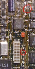
Has the board been cleaned? It looks like there is either still residual leaked fluid on the board, or the board has been severely damaged due to the leaked fluid. If you've not cleaned the board, you need to do so. Some people like the dishwasher, but I have no experience with that. I use dehydrated Ethanol made for electronics cleaning to clean my boards.
Also, is that a human hair I see going from "J12" to "Y2 OSC" to "8"? Or is that a deep scratch that cuts through traces? You really need a Digital Multi-Meter with Continuity Check mode to verify the integrity of your traces. To do that, you put both probes across a wire you want to check, and then the meter will usually emit a beep so long as continuity is being made.
Also, is that a human hair I see going from "J12" to "Y2 OSC" to "8"? Or is that a deep scratch that cuts through traces? You really need a Digital Multi-Meter with Continuity Check mode to verify the integrity of your traces. To do that, you put both probes across a wire you want to check, and then the meter will usually emit a beep so long as continuity is being made.
Hi,
The residue you see is the solder flux I used to remove the old capacitors, and the "human hair" thing you see is just that, a human hair!
I used the dishwasher method to clean it, so there shouldn't be any old capacitor fluid.
I am pretty sure the vast majority of traces are sound. Also, I doubt any serious damage to them has occurred due to capacitor fluid.
I do not have a continuity tester yet. I will see if I can get one soon.
I'll also try to get better pictures up here when I can.
c
The residue you see is the solder flux I used to remove the old capacitors, and the "human hair" thing you see is just that, a human hair!
I used the dishwasher method to clean it, so there shouldn't be any old capacitor fluid.
I am pretty sure the vast majority of traces are sound. Also, I doubt any serious damage to them has occurred due to capacitor fluid.
I do not have a continuity tester yet. I will see if I can get one soon.
I'll also try to get better pictures up here when I can.
c
Don't feel bad if you have these issues -- I lifted two pads on my current board in now (works fine now) and lifted a pad on C9 Positive (+) on my spare board, yet to be tested.
You have two lifted pads, both are completely fixable. C8 (-) goes to Pin 6 of Port J12, and C6 (+) goes to UB11 pin 2. You can just run a wire of the right wattage rating to those locations. See diagram below.
Most good/decent volt-ohm meters have a continuity test. You can use a ohm test also, just make sure you read something like 002mOhms or something like that. Something to indicate continuity. The continuity test beep is just for speed and convenience. You will need some sort of DMM. Period. (There's always a need for one of those around wherever you go.)
Clean the board again with something proper that won't isn't an aggressive attacker of delicate substances. I used 99% alcohol and a clean used toothbrush.

You have two lifted pads, both are completely fixable. C8 (-) goes to Pin 6 of Port J12, and C6 (+) goes to UB11 pin 2. You can just run a wire of the right wattage rating to those locations. See diagram below.
Most good/decent volt-ohm meters have a continuity test. You can use a ohm test also, just make sure you read something like 002mOhms or something like that. Something to indicate continuity. The continuity test beep is just for speed and convenience. You will need some sort of DMM. Period. (There's always a need for one of those around wherever you go.)
Clean the board again with something proper that won't isn't an aggressive attacker of delicate substances. I used 99% alcohol and a clean used toothbrush.
Here is the dehydrated 99.5% pure Ethanol (alcohol) I always use:
http://web.archive.org/web/20080131132706/http://chie.kenko.com/chie/product/item/itm_7731096072.html
(I live in Japan, which is why that page is in Japanese. I'm not even sure you can get it in the US due to the laws there. Some Americans are stupid enough to imbibe the stuff. The Japanese aren't.)
http://web.archive.org/web/20080131132706/http://chie.kenko.com/chie/product/item/itm_7731096072.html
(I live in Japan, which is why that page is in Japanese. I'm not even sure you can get it in the US due to the laws there. Some Americans are stupid enough to imbibe the stuff. The Japanese aren't.)
Mk. 558: Thank you for the wonderful diagram! I will find that quite useful, I'm sure.And thank you also for the support, though I don't feel too bad about it, I'm just stumped. I usually like to figure these things out myself, but I don't think I have the patience for this one (and I may cause more severe damage if I'm not careful).
JDW: Thank you about the ethanol, but I don't think I need it for now, but, incase I do in the future, would Denatured Alcohol work as a substitute? I think it should be similar enough, but it's proportion of alcohol to water might be slightly different. I'll continue to use the dishwasher method for now, because it seems to work for me (these old boards come out looking almost like new!)
I'll try your suggestions and will return with the results. It may take awhile, so please be patient...
c
JDW: Thank you about the ethanol, but I don't think I need it for now, but, incase I do in the future, would Denatured Alcohol work as a substitute? I think it should be similar enough, but it's proportion of alcohol to water might be slightly different. I'll continue to use the dishwasher method for now, because it seems to work for me (these old boards come out looking almost like new!)
I'll try your suggestions and will return with the results. It may take awhile, so please be patient...
c
70% rubbing alcohol will work. It just might leave a residue. You also will need to put a fan or hairdryer on your board a while before you connect it, to ensure all the water is dried up. My Ethanol is nearly 100% pure so it all dries up very fast even without a fan.
OK,
JDW: I'm not too concerned about residue. However, will it do any harm? I would think not (unless, of course, it's corrosive, like the capacitor fluid, which, in the case of rubbing alcohol, I doubt).
theos911: I'm not too worried about drying time. As JDW said, I could just wave a hair dryer at it to speed up the drying process.
As I said earlier, I'll probably stick with the dishwasher method; it seems to work very well for me.
Thank you!
c
JDW: I'm not too concerned about residue. However, will it do any harm? I would think not (unless, of course, it's corrosive, like the capacitor fluid, which, in the case of rubbing alcohol, I doubt).
theos911: I'm not too worried about drying time. As JDW said, I could just wave a hair dryer at it to speed up the drying process.
As I said earlier, I'll probably stick with the dishwasher method; it seems to work very well for me.
Thank you!
c
Good! I don't really care if it's unsightly (it's hidden inside, after all...), as long as it doesn't do harm.
I'll probably clean it up, put on capacitors, and reroute the missing pads sometime soon.
Thank you all for your help! This is a very positive experience so far.
c
I'll probably clean it up, put on capacitors, and reroute the missing pads sometime soon.
Thank you all for your help! This is a very positive experience so far.
c
Mk.558,
I think there's an error on the pic of the SE/30 Trace-outs. C8 (-) does go to Pin #6 of J12, but C6 (+) actually connects with Pin #7 of UB11. And the UB11's pin-outs are not number counter-clockwise.
CC_333,
just so you know, the numbering of pins/legs on all ICs usually go in counter-clockwise rotation. So, for UB11, look for the little notch on the side of the IC (facing C4), the last leg/pin on the top right is Pin #1, then the one next to it is Pin #2, next one down the line is Pin #3, and so on. When you reach the furthest top left pin/leg (Pin # 8) , then move to the 1st bottom left pin (Pin #9), moving to the right, next in line is Pin #10, and so on.
73s de Phreakout. :rambo:
I think there's an error on the pic of the SE/30 Trace-outs. C8 (-) does go to Pin #6 of J12, but C6 (+) actually connects with Pin #7 of UB11. And the UB11's pin-outs are not number counter-clockwise.
CC_333,
just so you know, the numbering of pins/legs on all ICs usually go in counter-clockwise rotation. So, for UB11, look for the little notch on the side of the IC (facing C4), the last leg/pin on the top right is Pin #1, then the one next to it is Pin #2, next one down the line is Pin #3, and so on. When you reach the furthest top left pin/leg (Pin # 8) , then move to the 1st bottom left pin (Pin #9), moving to the right, next in line is Pin #10, and so on.
73s de Phreakout. :rambo:
Update:
I tried reworking C8 and C6, but without success. I soldered a jumper between C6 positive and pin 6 of UB11, which apparently worked (there is sound), but there's still no video (I suspect C8, but I'm not sure what it does exactly).
I got a multimeter, so I can test for shorts and stuff.
I don't know exactly what to test, so tell me what to check and I'll check it.
c
I tried reworking C8 and C6, but without success. I soldered a jumper between C6 positive and pin 6 of UB11, which apparently worked (there is sound), but there's still no video (I suspect C8, but I'm not sure what it does exactly).
I got a multimeter, so I can test for shorts and stuff.
I don't know exactly what to test, so tell me what to check and I'll check it.
c
phreakout is absolutely correct about the Postive (+) side of capacitor C6 routing to pin-7 of sound chip UB11. It does not route to pin-2. Therefore, whoever is responsible for maintaining the following graphic should update that part immediately:
http://i26.photobucket.com/albums/c113/Starofire/Random/2d9cbc05.jpg
http://i26.photobucket.com/albums/c113/Starofire/Random/2d9cbc05.jpg
Another Update:
I redid my work with C8 using smaller wire, checked everything with a continuity tester, and it still isn't working.
Would UC6, UE6, UG6, UI6, UC7, UE7 and UG7 have anything to do with video? If so, could a failure in any of those cause the symptoms I'm experiencing?
Or maybe there are other possibilities?
If anything, this is a good learning experience.
c
I redid my work with C8 using smaller wire, checked everything with a continuity tester, and it still isn't working.
Would UC6, UE6, UG6, UI6, UC7, UE7 and UG7 have anything to do with video? If so, could a failure in any of those cause the symptoms I'm experiencing?
Or maybe there are other possibilities?
If anything, this is a good learning experience.
c
Can you verify with us that C6 and C8 are connected right? C8 (-) goes to Pin #6 of J12, and C6 (+) connects with Pin #7 of UB11. UB10 and UB11 are the two sound chips on that board.
Position the board so that the notches on the top of those chips are facing to the right. The leg/contact on the top right-hand side of UB11 and UB10 is Pin #1, next to that leg (moving to the left) is Pin #2, next to that leg (moving to the left) is Pin #3, and so on. The last pin on the top left-hand side is Pin #8, then move down to the bottom row starting with the bottom left-hand side. The first pin on the left is #9, next to that is Pin #10, next to that is Pin #11, and so on. All chips, whether they are square or rectangle, surface mounted or not, have their legs/contacts/pins numbered counter-clockwise.
Regarding UC6, UE6, UG6, UI6, UC7, UE7 and UG7, if I recall correctly, those are part of the video circuitry. There are other smaller chips that sit in-between that group, C2 and C7, that might be part of that circuit as well. The problem is that there are at least 3 different revisions of the SE/30 logic boards in its nearly 2 year existence and each may be slightly changed. One revision is in regard to boards made in Ireland; those were in fact built more reliable through using some more stable parts and better quality control.
73s de Phreakout. :rambo:
Position the board so that the notches on the top of those chips are facing to the right. The leg/contact on the top right-hand side of UB11 and UB10 is Pin #1, next to that leg (moving to the left) is Pin #2, next to that leg (moving to the left) is Pin #3, and so on. The last pin on the top left-hand side is Pin #8, then move down to the bottom row starting with the bottom left-hand side. The first pin on the left is #9, next to that is Pin #10, next to that is Pin #11, and so on. All chips, whether they are square or rectangle, surface mounted or not, have their legs/contacts/pins numbered counter-clockwise.
Regarding UC6, UE6, UG6, UI6, UC7, UE7 and UG7, if I recall correctly, those are part of the video circuitry. There are other smaller chips that sit in-between that group, C2 and C7, that might be part of that circuit as well. The problem is that there are at least 3 different revisions of the SE/30 logic boards in its nearly 2 year existence and each may be slightly changed. One revision is in regard to boards made in Ireland; those were in fact built more reliable through using some more stable parts and better quality control.
73s de Phreakout. :rambo:
Hi, phreakout,
C6 and C8 are verified. I checked them time and time again with a continuity tester, probing each capacitor and the appropriate pin(s) on the components they're supposed to connect to. The tester beeped, which I assume means that there's good contact among all the parts in question. I doubt the capacitors are the problem at this point.
As for the UC6, UE6, etc., I tried reseating them with no change. Could a failed one of these cause this problem? Is there a way to test them?
Also, how do I tell which revision this board is? It has a socketed CPU, if that means anything.
I feel that we're getting somewhat closer to the solution (I think?).
c
C6 and C8 are verified. I checked them time and time again with a continuity tester, probing each capacitor and the appropriate pin(s) on the components they're supposed to connect to. The tester beeped, which I assume means that there's good contact among all the parts in question. I doubt the capacitors are the problem at this point.
As for the UC6, UE6, etc., I tried reseating them with no change. Could a failed one of these cause this problem? Is there a way to test them?
Also, how do I tell which revision this board is? It has a socketed CPU, if that means anything.
I feel that we're getting somewhat closer to the solution (I think?).
c
The boards made in Ireland are lighter in green color, have a white colored PDS slot and the Bourns network filters (RP2, RP3 and RP10) are white or thin black-white colored covers as well. Plus, obviously, there is a sticker near the ROM SIMM that says "Assembled in Ireland" plain as day.
The remaining 2 other board revisions are the darker color green, have a black colored PDS slot and the Bourns network filters (RP2, RP3 and RP10) are either dark tan/beige or brown colored. I think these boards were either assembled in Mexico, USA, China, Korea, maybe even Thailand, Philippines or Japan; it's hard to say.
Those video chips can be a real pain to extract, at least from my experience. Part of the problem I'm encountering are my soldering irons and the solder Apple used on the original parts. That solder was formulated for low temperature soldering and has silicon or not enough flux in the mixture; it turns grainy and cloudy after hardening and aging. I could really use a soldering iron tip designed to heat up and desolder those type of chips, without any damage, and fits 20 to 40 watt Weller and Radio Shack irons. After I get the chips removed and the salvaged replacements ready to go, I'll be installing chip sockets FIRST on the board, then plug the chips in their sockets. I can't stress it any further how much of a pet peeve it is for me to have chips without their sockets!! >

73s de Phreakout. :rambo:
The remaining 2 other board revisions are the darker color green, have a black colored PDS slot and the Bourns network filters (RP2, RP3 and RP10) are either dark tan/beige or brown colored. I think these boards were either assembled in Mexico, USA, China, Korea, maybe even Thailand, Philippines or Japan; it's hard to say.
Those video chips can be a real pain to extract, at least from my experience. Part of the problem I'm encountering are my soldering irons and the solder Apple used on the original parts. That solder was formulated for low temperature soldering and has silicon or not enough flux in the mixture; it turns grainy and cloudy after hardening and aging. I could really use a soldering iron tip designed to heat up and desolder those type of chips, without any damage, and fits 20 to 40 watt Weller and Radio Shack irons. After I get the chips removed and the salvaged replacements ready to go, I'll be installing chip sockets FIRST on the board, then plug the chips in their sockets. I can't stress it any further how much of a pet peeve it is for me to have chips without their sockets!! >
73s de Phreakout. :rambo:
Well,
As I was reseating the socketed ones, I noticed that one of them didn't mach the rest (UE6), it's thicker looking and the markings are different from the others.
I swapped it with the equivalent on the other dead board without change. By the way, the other dead board has the same exact problem.
What are the odds that both could've failed with the same problem?
Also, I actually have one of those Made in Ireland boards, except it needs to be bent a certain way in order to work (the symptoms are similar, except it's completely dead; no sound, no video). I assume it's a bad trace somewhere.
c
As I was reseating the socketed ones, I noticed that one of them didn't mach the rest (UE6), it's thicker looking and the markings are different from the others.
I swapped it with the equivalent on the other dead board without change. By the way, the other dead board has the same exact problem.
What are the odds that both could've failed with the same problem?
Also, I actually have one of those Made in Ireland boards, except it needs to be bent a certain way in order to work (the symptoms are similar, except it's completely dead; no sound, no video). I assume it's a bad trace somewhere.
c
I'm working on Rev 2.0 of the capacitor diagram right now.
Note to the iBook: It's not a big deal if I spend 45 minutes trying to set up a nice drawing of a Sony Stereo Sound Chip and I go press Delete and you somehow confuse that with logging out. Of course there is a autosave function in AppleWorks but apparently that was on vacation. Bullocks -- this time we redraw the whole thing scaled up 3x (Yes I measured the sound chip and it's 6x19mm) and put nice "SONY 03E03G ..." on it.
It'll be better this time because apparently I forgot to include the half circle indentation on the last drawing, so the reference to Pin 1 was unobtainable because there was no reference mark. That's okay I look at it now and it looks all fugly anyways, polluting JDW's nice socketed motherboard image with terrible graphics. Steve Jobs would have told me off in front of a crowd for that. :disapprove:
Note to the iBook: It's not a big deal if I spend 45 minutes trying to set up a nice drawing of a Sony Stereo Sound Chip and I go press Delete and you somehow confuse that with logging out. Of course there is a autosave function in AppleWorks but apparently that was on vacation. Bullocks -- this time we redraw the whole thing scaled up 3x (Yes I measured the sound chip and it's 6x19mm) and put nice "SONY 03E03G ..." on it.
It'll be better this time because apparently I forgot to include the half circle indentation on the last drawing, so the reference to Pin 1 was unobtainable because there was no reference mark. That's okay I look at it now and it looks all fugly anyways, polluting JDW's nice socketed motherboard image with terrible graphics. Steve Jobs would have told me off in front of a crowd for that. :disapprove:
OK. I await your Rev. 2.0!
Meanwhile, I've given up on the one SE/30 board (the one I've been talking about) for now, and am instead concentrating my efforts on this apparently made in Ireland board that will only work if I bend it a certain way. I've concluded that it's either a bad trace somewhere or a bad solder joint somewhere (I noticed that it gets somewhat better when it's warm, so it could be heat/age related).
I would like to get these boards working, but I'm not sure if I'm competent enough at this point to do it myself (although I'm learning fast!)
Until next time...
c
Meanwhile, I've given up on the one SE/30 board (the one I've been talking about) for now, and am instead concentrating my efforts on this apparently made in Ireland board that will only work if I bend it a certain way. I've concluded that it's either a bad trace somewhere or a bad solder joint somewhere (I noticed that it gets somewhat better when it's warm, so it could be heat/age related).
I would like to get these boards working, but I'm not sure if I'm competent enough at this point to do it myself (although I'm learning fast!)
Until next time...
c
Great!
That would be nice. I have two (hence the topic name), but I will deal with the one which I tried to rework (and therefore should technically function properly, if not for this latent and as of yet unknown problem).
I guess I'll mail it??
It'll figure itself out, I suppose...
c
That would be nice. I have two (hence the topic name), but I will deal with the one which I tried to rework (and therefore should technically function properly, if not for this latent and as of yet unknown problem).
I guess I'll mail it??
It'll figure itself out, I suppose...
c
I would send them both. What you may think is one way, but could be different than the boards actual condition. I am in the states, and send me a PM.
Reason I say this, if it comes down to being a rare or impossible chip to replace thats actually bad, it may be a different chip on the opposite board, and i could make 1 board work from 2.
Then again, i could fix both of them. Never know.
Reason I say this, if it comes down to being a rare or impossible chip to replace thats actually bad, it may be a different chip on the opposite board, and i could make 1 board work from 2.
Then again, i could fix both of them. Never know.
Ta Da!
It's a US Legal size image (try a Super A4 ISO size at 22.7x35.6cm if you're outside the US) , so it should print out fine if you have that capability. It was designed originally to fit on 8.5x11 US Letter but there simply wasn't enough room (and that was before I added the Procedure part, and the Polarities section). Then I tried A4, and nope. The Legal size is just barely enough to contain practically everything you need. I did it all with AppleWorks 6.2.9...I really should move on and discover proper image and drawing applications :disapprove:
Notice: All functions of the capacitors are not set in stone. Still waiting on some expert advice based on detailed circuit analysis. I have a copy of the BOMARC and Apple diagrams if anybody wants to tackle that (shouldn't take long).
It's a US Legal size image (try a Super A4 ISO size at 22.7x35.6cm if you're outside the US) , so it should print out fine if you have that capability. It was designed originally to fit on 8.5x11 US Letter but there simply wasn't enough room (and that was before I added the Procedure part, and the Polarities section). Then I tried A4, and nope. The Legal size is just barely enough to contain practically everything you need. I did it all with AppleWorks 6.2.9...I really should move on and discover proper image and drawing applications :disapprove:
Notice: All functions of the capacitors are not set in stone. Still waiting on some expert advice based on detailed circuit analysis. I have a copy of the BOMARC and Apple diagrams if anybody wants to tackle that (shouldn't take long).
I had received the boards today.
I realize you were trying to learn, and i cannot knock on anyone for trying and learning. However constructive criticism says this:
Need to be a lot less sloppy with the soldering iron. You have done some extreme damage to the boards. Im sure i can fix it, but the thing that bothers me are the vias. its like you drilled out the vias? you cannot do this. ever.... you will break connections between layers of the PCB. and possibly short layer-to-layer. Trust me, i know....
These are 4 layer boards, and traces run from layer to layer. Each traces is connected between layers if routed between layers, through a Via. If the via is broken/drilled/etc you can damage the the inter-layer connection. Anyway, I have schematics so its not difficult for me to fix. I just have to hope layers arnt shorted, or i will have to cut traces, and route around it to clear the shorts.
Also on one board, I noticed you have a bare copper wire run from C8 all the way around to the bottom of the board. I am not going to explain the reasons why this is a bad idea ;-)
On the flip side though, it seems besides the ones with broken pads, you got the capacitors soldered in place perfectly fine. No problems there, good job
So... What I am going to do, is fix these boards, I will document everything that I do, on my youtube channel, etc... Therefore, I recommend you and everyone who has a modern computer, watch youtube, and use this as a learning experience in case the same thing happens to anyone else.
Stuff happens, no one can predict it. All we can do as human beings is learn from it. So we shall
I am heading up to parts express tomorrow because I have to restock on my caps so I can do the other 2 boards. I use radials. I dont use tantalum because I dont like the spontaneous shorting that could happen when they age. When tantalum caps get old, they start to become noisy when DC leakage starts to creep in. Then sometimes they will just short. Which in high current circuits result in a BANG.
P.S. I am sorry, I am trying to not be offensive to anyone. I am simply stating my findings, and mention ways to work around it and learn from it, as we have to fix this before I can begin further troubleshooting of which IC could have taken a hit.
I realize you were trying to learn, and i cannot knock on anyone for trying and learning. However constructive criticism says this:
Need to be a lot less sloppy with the soldering iron. You have done some extreme damage to the boards. Im sure i can fix it, but the thing that bothers me are the vias. its like you drilled out the vias? you cannot do this. ever.... you will break connections between layers of the PCB. and possibly short layer-to-layer. Trust me, i know....
These are 4 layer boards, and traces run from layer to layer. Each traces is connected between layers if routed between layers, through a Via. If the via is broken/drilled/etc you can damage the the inter-layer connection. Anyway, I have schematics so its not difficult for me to fix. I just have to hope layers arnt shorted, or i will have to cut traces, and route around it to clear the shorts.
Also on one board, I noticed you have a bare copper wire run from C8 all the way around to the bottom of the board. I am not going to explain the reasons why this is a bad idea ;-)
On the flip side though, it seems besides the ones with broken pads, you got the capacitors soldered in place perfectly fine. No problems there, good job
So... What I am going to do, is fix these boards, I will document everything that I do, on my youtube channel, etc... Therefore, I recommend you and everyone who has a modern computer, watch youtube, and use this as a learning experience in case the same thing happens to anyone else.
Stuff happens, no one can predict it. All we can do as human beings is learn from it. So we shall
I am heading up to parts express tomorrow because I have to restock on my caps so I can do the other 2 boards. I use radials. I dont use tantalum because I dont like the spontaneous shorting that could happen when they age. When tantalum caps get old, they start to become noisy when DC leakage starts to creep in. Then sometimes they will just short. Which in high current circuits result in a BANG.
P.S. I am sorry, I am trying to not be offensive to anyone. I am simply stating my findings, and mention ways to work around it and learn from it, as we have to fix this before I can begin further troubleshooting of which IC could have taken a hit.
Wow. Techknight, that sounds so bad that I simply MUST see a photo! I think we can keep it anonymous so the original owner won't get embarrassed or offended. But if my board photos can serve as an example of what to do, it would also be good to have photos of "what NOT to do!"
Well like i said, I am trying not to offend the rightful owner. I am trying to be constructive about this and not hurt anyone's feelings. He tried, and he actually did pretty good on the install of the new caps. its just that some errors were made that shouldnt have been.
Well, then take a photo "with the owner's consent" of course. My think is that a photo showing "what not to do" might help others avoid the same mistakes in the future. It seems like such is needed in light of the fact many of these folks have seen my "BEFORE/AFTER photos" but still are making these kind of mistakes.
Hi, all,
Well, all I can say is I'm learning.
This is a very important learning experience.
Hopefully, techknight can help me out of my hole, and I can then proceed to learn more so these mistakes don't happen again.
Thank you all for the invaluable information and wonderful help.
c
Well, all I can say is I'm learning.
This is a very important learning experience.
Hopefully, techknight can help me out of my hole, and I can then proceed to learn more so these mistakes don't happen again.
Thank you all for the invaluable information and wonderful help.
c
Thats why i will video/photo document my proceedures. this way, you and everyone can learn from it, and when the next capacitor replacement comes on a new conquest, You can perform it with confidence
Oh, also, I want to teach you all this tidbit:
Routing through a via is often easier than taking a route around the entire board. Ratshack sells 30 guage wire, which is fine wire. This wire is small enough when stripped, will fit through an existing via to reconnect a broken via trace segment.
Also flux and tin the via with fresh solder BEFORE soldering anything to it, in it, or on it.
Oh, also, I want to teach you all this tidbit:
Routing through a via is often easier than taking a route around the entire board. Ratshack sells 30 guage wire, which is fine wire. This wire is small enough when stripped, will fit through an existing via to reconnect a broken via trace segment.
Also flux and tin the via with fresh solder BEFORE soldering anything to it, in it, or on it.
I'm eager for photos, too.
If I do this kind of restoration/repair again (and I probably will), I'd like to see the right way is versus the wrong way so I don't make the same mistake(s) unknowingly.
c
p.s. A question for techknight: Aren't tantalum-type capacitors supposed to last longer?
If I do this kind of restoration/repair again (and I probably will), I'd like to see the right way is versus the wrong way so I don't make the same mistake(s) unknowingly.
c
p.s. A question for techknight: Aren't tantalum-type capacitors supposed to last longer?
They do. Certainly. BUT I just dont like the fact when they DO decide to fail, they fail violently.
I would rather recap again in another 10 years versus a tantalum blow-out and have a bad board because of it. Its hard to find SE/30 parts now, What about 10 years from now?
I would rather recap again in another 10 years versus a tantalum blow-out and have a bad board because of it. Its hard to find SE/30 parts now, What about 10 years from now?


I agree 100%. I use Panasonic FP SMD radial capacitors for recapping: these have low ESR values, almost as low as Tantalums.
I have seen many logic boards were Apple used a combination of Tantalum and radial SMD capacitors so there must be a reason for doing so.
Probably because with Tantalum capacitors their failure mode tends to be by short-circuit.
Anyway, I guess the Panasonic FP capacitors will good for about 15 years.
The fluid filled caps will indeed last a mere 15 to 20 years. And although it's true that shorts kill tantalums, shorts also kill fluid filled caps too! So when speaking of recapping an SE/30 motherboard, the merits are on the side of the tantalums because the tantalums have no 15-20 year life limit (they can't ever "leak"). The only 2 exceptions are C2 and C11, which are too big in terms of capacity (and voltage specification) to be replaced by tantalums -- you'll still have to replace those every 15 to 20 years.
Yea, Tantalum caps are fine usually but i just prefer not to use them based on my own judgement. Albeit I dont think i have seen very many shorted tantalums. Maybe 6 or so for the 15 or so years ive been repairing electronics. (been doing it since i was a low teen, 27 now). I have seen a crapload of leaky electrolytics both electrically and physically, but i have only seen ONE shorted lytic, and it just so happened to be in a vintage Harmon Kardon receiver of all things, part of the DC protect soft-start circuit.
For the record, I have seen leaky and shorted ceramic capacitors roughly about the same order of magnitude as any other capacitor. Its all a crapshoot. its guaranteed anything electronic will fail eventually. I remember working on the older Hitachi ultravision SD projection sets, and seeing that nicely exploded ceramic capacitor right off the horizontal output transistor in those sets. Always took out the B+ picofuse every time. I even remember seeing a similar issue on zenith sets as well.
Edit: P.S. actually come to think of it, I found another shorted electrolytic. I was working on an Apple multiscan 15" monitor way back in the day, that all it did was power up and shoot a bright squiggly line up the center of the screen and pulsate. Done this every 2 seconds. Turned out to be a shorted and physically leaking small electrolytic and a transistor right next to it in the same circuit. I vaguely remember it being near the flyback in the horizontal stage.
For the record, I have seen leaky and shorted ceramic capacitors roughly about the same order of magnitude as any other capacitor. Its all a crapshoot. its guaranteed anything electronic will fail eventually. I remember working on the older Hitachi ultravision SD projection sets, and seeing that nicely exploded ceramic capacitor right off the horizontal output transistor in those sets. Always took out the B+ picofuse every time. I even remember seeing a similar issue on zenith sets as well.
Edit: P.S. actually come to think of it, I found another shorted electrolytic. I was working on an Apple multiscan 15" monitor way back in the day, that all it did was power up and shoot a bright squiggly line up the center of the screen and pulsate. Done this every 2 seconds. Turned out to be a shorted and physically leaking small electrolytic and a transistor right next to it in the same circuit. I vaguely remember it being near the flyback in the horizontal stage.
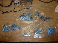
Through-hole components for an SMT design....hmmm...might as well get SMT electrolytic ones if you're going through the trouble of repairing the boards.
nvdeynde, do you have part numbers for the caps you used? I might recap my socketed board with the kind you used.
nvdeynde, do you have part numbers for the caps you used? I might recap my socketed board with the kind you used.
Good!
I'm glad to hear one of the three boards are working.
I will abandon this topic now, so thank you once again!
c
Edit: p.s. I must admit, it would seem to me that this post has inadvertently served as a catalyst for the emergence of a lot of useful information for those wishing to restore/repair their SE/30s.
I'm glad to hear one of the three boards are working.
I will abandon this topic now, so thank you once again!
c
Edit: p.s. I must admit, it would seem to me that this post has inadvertently served as a catalyst for the emergence of a lot of useful information for those wishing to restore/repair their SE/30s.
Version 2.1 released. Should be final release.
http://i26.photobucket.com/albums/c113/Starofire/Random/2d9cbc05.jpg
After much wrangling and making errors uploading to PhotoBucket...
If anybody wants the .cwk AppleWorks document for shameless theft plagarization rip-off rebranding under your own identity "borrowing" copying "I was just reusing it" "I was reworking it" "I was rebuilding it" useful works, just ask.
Extra helping of ink-sogged printer paper is included free of charge. Reminds me of my high school "House" project on Argentina. The tables for economic data were so filled with color and shading like the image that I must have gone through a single color ink cartridge for just that project.
http://i26.photobucket.com/albums/c113/Starofire/Random/2d9cbc05.jpg
After much wrangling and making errors uploading to PhotoBucket...
If anybody wants the .cwk AppleWorks document for shameless theft plagarization rip-off rebranding under your own identity "borrowing" copying "I was just reusing it" "I was reworking it" "I was rebuilding it" useful works, just ask.
Extra helping of ink-sogged printer paper is included free of charge.
Reminds me of my high school "House" project on Argentina. The tables for economic data were so filled with color and shading like the image that I must have gone through a single color ink cartridge for just that project.Looks good bro.
Also as a side note, people with no chime no video, or stuck simasimac, check those filter chokes!
Same thing with the failure of SCSI. Check the filter choke!! if something over-draws on the TermPower, it can open the filter choke which cuts V supply to the SCSI IC too!
Also as a side note, people with no chime no video, or stuck simasimac, check those filter chokes!
Same thing with the failure of SCSI. Check the filter choke!! if something over-draws on the TermPower, it can open the filter choke which cuts V supply to the SCSI IC too!