
Thread
Macintosh Portable 34 pin to 50 pin SCSI cable
Hi,
I have a very nice functioning Portable but I'm worried about the 20+ year old HDD. I'd love to replace it with a CF card, but for that I'd need one of those infamous 34-to-50 adapter cables. I don't really want to risk making my own. I'm wondering if someone here maybe has a spare one, or could make one for me?
Given that I'm new here I'd gladly pay in advance.
TIA!
I have a very nice functioning Portable but I'm worried about the 20+ year old HDD. I'd love to replace it with a CF card, but for that I'd need one of those infamous 34-to-50 adapter cables. I don't really want to risk making my own. I'm wondering if someone here maybe has a spare one, or could make one for me?
Given that I'm new here I'd gladly pay in advance.
TIA!
Where are you located?
USA, Southern NH and Boston for the most part, but I very frequently travel to Europe as well.
I posted the pinout info necessary to build this adapter cable in a previous thread about the luggable. It's very straightforward . . .
. . . but a double ended, or double sided, adapter PCB for 2.5" PowerBook SCSI Drive RA socket and a 3.5" SCSI cable header would be a great community project. :?:
. . . but a double ended, or double sided, adapter PCB for 2.5" PowerBook SCSI Drive RA socket and a 3.5" SCSI cable header would be a great community project. :?:
Thanks, I did see the pinout post but I'm not sure where I'd source the parts, and then there's the time needed... oh hell, the truth is I'm just a bit clumsy. I really wouldn't mind paying for a pre-made cable though.
Heh! I finally found it too!

from: Lot of Goodness
Have you got the SCSI interface for the CF Card already?
If so what is the form factor of the adapter and the spec for the connector?
If you don't have the adapter yet, get that end of it nailed down before worrying about the cable.
from: Lot of Goodness
Have you got the SCSI interface for the CF Card already?
If so what is the form factor of the adapter and the spec for the connector?
If you don't have the adapter yet, get that end of it nailed down before worrying about the cable.
I bought a CF ActecMonster and was planning on using that with a 4GB CF card. In case that doesn't work I have a couple of IDE-SCSI bridges, one with a standard 50-pin SCSI connector (and the usual 4-pin Molex power) the other with a UW connector but I have an adapter to convert that to the old 50-pin standard.
Regardless of the drive used, it's the usual 50-pin SCSI and 4-pin Molex connectors.
Regardless of the drive used, it's the usual 50-pin SCSI and 4-pin Molex connectors.
With a bit of careful keyword search massaging, one can often find oddball connectors on ebay in small quantities.
I made mine with a 50-pin SCSI ribbon cable, a 34-pin floppy drive ribbon cable and a razor blade. I used the SCSI connector and it's cable but only a connector from the floppy cable. I sliced up the individual wires from the ribbon and followed the pinout chart to connect them to the floppy connector. It took maybe an hour and didn't cost me anything as I already had the parts on hand.
Very clever solution!
tmtomh is right, this is a clever way to do this particular adaptation. I like this approach because it's a down and dirty conversion that keeps all the wires the same length. did you start with a long section of ribbon cable and twist the signal lines? The shield lines of the alternating pairs would be tied back to to common ground on the HDD's PCB.
mcd, you lifted the Insulation Displacement Connector's (IDC) strain relief and lid? That's the way I've done the same thing in the past for testing. I wound up making a PCB to do two different adaptations at once for the project along with providing the mounting unit. I'd still like to see an adapter PCB done that acts as a mounting board for a 2.5" lappy HDD in the Luggable.
Are you using a 3.5" HDD or a 2.5" Lappy Drive with an adapter with that cable in your luggalbe?
. . . meanwhile, back at the banana ranch:
Google searsh string: idc ribbon cable assembly howto
http://www.thekanes.org/2010/02/07/how-to-make-a-ribbon-cable/
(PDF) IDC Cable, Headers & Connectors
IDC (Insulation Displacement Connector) Ribbon Cable
Happy hacking, m!
mcd, you lifted the Insulation Displacement Connector's (IDC) strain relief and lid? That's the way I've done the same thing in the past for testing. I wound up making a PCB to do two different adaptations at once for the project along with providing the mounting unit. I'd still like to see an adapter PCB done that acts as a mounting board for a 2.5" lappy HDD in the Luggable.
Are you using a 3.5" HDD or a 2.5" Lappy Drive with an adapter with that cable in your luggalbe?
. . . meanwhile, back at the banana ranch:
Google searsh string: idc ribbon cable assembly howto
http://www.thekanes.org/2010/02/07/how-to-make-a-ribbon-cable/
(PDF) IDC Cable, Headers & Connectors
IDC (Insulation Displacement Connector) Ribbon Cable
Happy hacking, m!
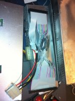
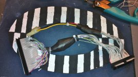
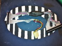
I think a picture is worth a thousand words here:

Yes, I lifted the top off the IDC, pressed the wires into the pin "teeth" and replaced the top. I also forgot that I used a separate set for the Molex power connection.
I made the cable but actually only used it for a few weeks with a standard, 3.5", 50-pin Apple SCSI drive. After that, I found a Conner drive to do a PCB swap with in order to have an "original" drive. But I'm a pack rat so I keep the cable around, just in case.
Yes, I lifted the top off the IDC, pressed the wires into the pin "teeth" and replaced the top. I also forgot that I used a separate set for the Molex power connection.
I made the cable but actually only used it for a few weeks with a standard, 3.5", 50-pin Apple SCSI drive. After that, I found a Conner drive to do a PCB swap with in order to have an "original" drive. But I'm a pack rat so I keep the cable around, just in case.
Eeeek! 8-o Bundling unshielded signal & address wires together like that is just begging for crosstalk problems on a parallel interface!
It'd be much better to split the cable so as to leave the signal/ground pairs intact right up to the 34 pin connector, twisting each pair several times on the way there and then nipping the ground wire just short of the connector, if not tying them together to ground at that end. That way you can bundle the twisted pairs together without too much worry about crosstalk rearing its ugly head.
Other than that one caveat, nice hack and very helpful piccie, mcd! :approve:
It'd be much better to split the cable so as to leave the signal/ground pairs intact right up to the 34 pin connector, twisting each pair several times on the way there and then nipping the ground wire just short of the connector, if not tying them together to ground at that end. That way you can bundle the twisted pairs together without too much worry about crosstalk rearing its ugly head.
Other than that one caveat, nice hack and very helpful piccie, mcd! :approve:
Hm, hadn't thought of that and I like the advice. I may be looking at making a new one just for fun, then  Thanks, Trash!
Thanks everyone!
So I'm buying these then:
http://www.amazon.com/gp/product/B007R2JL18
http://www.amazon.com/gp/product/B007R2JEV0
http://www.amazon.com/gp/product/B007R2JF9Q
I apologize for my ignorance but what exactly do I do with the wires that are not meant to be connected on the 34-pin side? It appears that all odd wires on the 50-pin side are left unconnected. Do I take the odd wires and twist them around the corresponding even ones, then just leave them unconnected right before the 34-pin connector?
I think I get the wiring diagram for the most part, but what happens with 11 & 16 on the 34-pin side? They are marked as GND and don't seem to not reach the 50-pin side at all. Does the 50-pin connector really not need any GNDs hooked up?
Finally, this is AztecMonster specific: the manual says the MacPlus will not boot from this "drive" without cutting wire 40 (RST). Is this anything I should worry about with the Portable?
So I'm buying these then:
http://www.amazon.com/gp/product/B007R2JL18
http://www.amazon.com/gp/product/B007R2JEV0
http://www.amazon.com/gp/product/B007R2JF9Q
I apologize for my ignorance but what exactly do I do with the wires that are not meant to be connected on the 34-pin side? It appears that all odd wires on the 50-pin side are left unconnected. Do I take the odd wires and twist them around the corresponding even ones, then just leave them unconnected right before the 34-pin connector?
I think I get the wiring diagram for the most part, but what happens with 11 & 16 on the 34-pin side? They are marked as GND and don't seem to not reach the 50-pin side at all. Does the 50-pin connector really not need any GNDs hooked up?
Finally, this is AztecMonster specific: the manual says the MacPlus will not boot from this "drive" without cutting wire 40 (RST). Is this anything I should worry about with the Portable?
I finally got around to making the cable. It's easier than I thought, but I'd need a couple of clarifications:
I'm assuming the GND wires on the 34-pin side can be connected to any one of the odd wires on the 50-pin side. Is that correct? Or should they be connected to the molex GND wire? (As per the photo of the completed cable, it seems the 50-pin connector's odd wires have been used.)
What about TPWR? Should I hook it up? The diagram shows pin 26 from the 50-pin side connected together with molex pin 4, and they also connect to pins 23, 24, 33, 34 on the 34-pin side. Is this the right way to do it? Or can leave TPWR disconnected on the 50-pin connector, and just connect molex pin 4 to the four pins on the 34-pin connector? I'm asking because on the photo above exactly this seems to have been done.
Thanks in advance!
I'm assuming the GND wires on the 34-pin side can be connected to any one of the odd wires on the 50-pin side. Is that correct? Or should they be connected to the molex GND wire? (As per the photo of the completed cable, it seems the 50-pin connector's odd wires have been used.)
What about TPWR? Should I hook it up? The diagram shows pin 26 from the 50-pin side connected together with molex pin 4, and they also connect to pins 23, 24, 33, 34 on the 34-pin side. Is this the right way to do it? Or can leave TPWR disconnected on the 50-pin connector, and just connect molex pin 4 to the four pins on the 34-pin connector? I'm asking because on the photo above exactly this seems to have been done.
Thanks in advance!
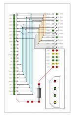
All the odd pins on the 50 Pin Connectors are tied to ground, I forgot to show that on the cleaned up version of the drawing. Other than the four
schematic, sorta . . .

I've shown TPWR to be tied to the Molex Connector on the cleaned up version of the drawing. Termination Power can probably be tied to the Molex Connector, but it's likely much better to connect it only to the SCSI Bus. There the 5V feed has hopefully been conditioned whereas the raw power feed at the Molex Connector certainly won't have been.
On second thought, keep it isolated, better safe than sorry. :approve:
Same thing for ground lines at the signal level, they had probably best be kept clean as well. Connect just pins 37-40 on the 34 pin connector to the Molex Ground Lines. Tie the rest to the SCSI Bus.
Remember, I'm just an electrical plumber, not really an electron pusher . . .
. . . never trust a guy who doesn't have, and know how to use, an Oscilloscope! :I
edit: see, never trust a . . . BooBoo been crossed out, correction: Pins 27-30, as noted by martona below. :I
schematic, sorta . . .
I've shown TPWR to be tied to the Molex Connector on the cleaned up version of the drawing. Termination Power can probably be tied to the Molex Connector, but it's likely much better to connect it only to the SCSI Bus. There the 5V feed has hopefully been conditioned whereas the raw power feed at the Molex Connector certainly won't have been.
On second thought, keep it isolated, better safe than sorry. :approve:
Same thing for ground lines at the signal level, they had probably best be kept clean as well. Connect just pins 37-40 on the 34 pin connector to the Molex Ground Lines. Tie the rest to the SCSI Bus.
Remember, I'm just an electrical plumber, not really an electron pusher . . .
. . . never trust a guy who doesn't have, and know how to use, an Oscilloscope! :I
edit: see, never trust a . . . BooBoo been crossed out, correction: Pins 27-30, as noted by martona below. :I
Thanks for the quick response! I'll finish the cable tomorrow, and... fingers xed. I have had the Portable recapped, all that's left to do is install the 8-meg RAM expansion and replace the noisy, power-hungry HD with a CF SCSI module.
I'll keep TPWR a single wire then, and based on the "unclean" drawing you just posted, it'll go to pin 34 on the Mac Portable side. All other 5V pins will go to the molex feed. Correct? I feel the need to ask because this isn't in line with the photo posted above, mcdermd seems to have used the molex connector solely for everything above pin 22, and I have to assume his 50-pin TPWR doesn't go anywhere.
Regarding GND, I'll use molex for pins 27,28,29 & 30. I'm using a couple of the odd SCSI bus lines for GND pins 6 & 11 (can't remember which ones I hooked up exactly). The rest of the odd lines on the 50-pin side are cut (other than the two I singled out for GND 6 & 11), just like on the photo; I'm assuming that's fine.
I'll keep TPWR a single wire then, and based on the "unclean" drawing you just posted, it'll go to pin 34 on the Mac Portable side. All other 5V pins will go to the molex feed. Correct? I feel the need to ask because this isn't in line with the photo posted above, mcdermd seems to have used the molex connector solely for everything above pin 22, and I have to assume his 50-pin TPWR doesn't go anywhere.
Regarding GND, I'll use molex for pins 27,28,29 & 30. I'm using a couple of the odd SCSI bus lines for GND pins 6 & 11 (can't remember which ones I hooked up exactly). The rest of the odd lines on the 50-pin side are cut (other than the two I singled out for GND 6 & 11), just like on the photo; I'm assuming that's fine.
That's what I meant . . . oops! 8-o
Strip your ribbon cable into signal/ground pairs, twist them a few times before terminating just the signal/control line on the IDC connection. You can snip the alternating (signal paired) ground lines just before they hit the the IDC connector. Running the twisted signal/ground pairs will help tremendously in keeping crosstalk at bay. See above.
Strip your ribbon cable into signal/ground pairs, twist them a few times before terminating just the signal/control line on the IDC connection. You can snip the alternating (signal paired) ground lines just before they hit the the IDC connector. Running the twisted signal/ground pairs will help tremendously in keeping crosstalk at bay. See above.
Thanks!
Yes, I saw the crosstalk mention above, but... but.. the photo...
To be perfectly honest I was concerned about not finding the right wire when I get to the 34-pin connector if I twist odd & even pairs together. That's why I cut the gordian knot, so to speak.
Of course I could have just used a sharpie before twisting the pairs. But such a "complicated" solution did not occur to me when I started, and It's too late now, I only need to do the DP wires and add the Molex connector.
I do have material for another cable, so I might make a proper one if this one works. (If it doesn't, I'll HAVE to make another one.)
Yes, I saw the crosstalk mention above, but... but.. the photo...
To be perfectly honest I was concerned about not finding the right wire when I get to the 34-pin connector if I twist odd & even pairs together. That's why I cut the gordian knot, so to speak.
Of course I could have just used a sharpie before twisting the pairs. But such a "complicated" solution did not occur to me when I started, and It's too late now, I only need to do the DP wires and add the Molex connector.
I do have material for another cable, so I might make a proper one if this one works. (If it doesn't, I'll HAVE to make another one.)
Well, the cable is finished. It's not pretty, but it's mine.
Now I'm off to hook it up. Hopefully there will be no smoke.

Now I'm off to hook it up. Hopefully there will be no smoke.
Easy trick.:
01) leave an extra couple of inches of ribbon sticking out the off end side of the 50 pin IDConnector
02) split all the wires on that side, lopping off the signal lines
03) the remaining lines will all be connected to the ground side of the cable, strip the ends
04) bundle them together and attach the alligator clip lead of a $.99 Continuity tester to the bundle
05) leave about an extra inch of length on the business end of the ribbon cable
06) mark across the entire width of the cable at the IDC point with a sharpie.
07) split all your pairs from the beginning to end
08) split that one inch extra on each twisted pair
09) apply continuity tester to see which of the pair doesn't light up
10) nip off the side that does light up about 1.5" short of the sharpie line with your dikes
11) strip the ground line waste off the signal line back to the nip
12) punch your signal lines down on the IDC connector's forks right at the sharpie line (for equal length signal correctness)
Did I mention using a Vise to do the final punchdown of the IDC tops?
01) leave an extra couple of inches of ribbon sticking out the off end side of the 50 pin IDConnector
02) split all the wires on that side, lopping off the signal lines
03) the remaining lines will all be connected to the ground side of the cable, strip the ends
04) bundle them together and attach the alligator clip lead of a $.99 Continuity tester to the bundle
05) leave about an extra inch of length on the business end of the ribbon cable
06) mark across the entire width of the cable at the IDC point with a sharpie.
07) split all your pairs from the beginning to end
08) split that one inch extra on each twisted pair
09) apply continuity tester to see which of the pair doesn't light up
10) nip off the side that does light up about 1.5" short of the sharpie line with your dikes
11) strip the ground line waste off the signal line back to the nip
12) punch your signal lines down on the IDC connector's forks right at the sharpie line (for equal length signal correctness)
Did I mention using a Vise to do the final punchdown of the IDC tops?
Thanks Trash80, that's actually pretty cool!
I may have to do another cable in which case I'll follow the above steps.
There was no smoke, but despite the below photos, it's not a complete success either.


I had to make one modification to the diagram: TERMPWR should be disconnected. All 5V pins from the 34-connector side go to the molex red wire. The TERMPWR line on the 50-pin side is cut. This way I got the Portable to recognize the disks. (In my photo above TERMPWR is still connected to a 5V pin, I had to change this to breathe life into the system but forgot to snap a new pic.) FWIW mcdermd's photo has TERMPWR disconnected too.
But I still have one problem. There may be something wrong with the cable I made, or the harddisks, or possibly the diagram, but here's the behavior I'm seeing:
- With the original 34-pin HD installed, the Portable powers on and boots fine.
- With the AztecMonster, the Portable powers on and after some deliberation it flashes the dreaded disk with a questionmark. At this point if I press the reset button on the machine it boots fine. (As per the photo above.) This isn't some one-off instability issue; out of 20 cold starts all of them went the same way. Have to wait for the flashing questionmark, then press reset to get it to recognize the HD.
- I tried it with a regular 50-pin Apple/IBM SCSI HD (it came from my Color Classic) and I get the same behavior: power on -> questionmark -> reset -> boot, so this isn't the AztecMonster's problem.
Any thoughts? Just for kicks I disconnected the RST wire temporarily, and that resulted in a no-boot scenario; the reset button stopped having an effect. Reconnecting RST reverted to the behavior described above.
I'm at a loss.
I may have to do another cable in which case I'll follow the above steps.
There was no smoke, but despite the below photos, it's not a complete success either.
I had to make one modification to the diagram: TERMPWR should be disconnected. All 5V pins from the 34-connector side go to the molex red wire. The TERMPWR line on the 50-pin side is cut. This way I got the Portable to recognize the disks. (In my photo above TERMPWR is still connected to a 5V pin, I had to change this to breathe life into the system but forgot to snap a new pic.) FWIW mcdermd's photo has TERMPWR disconnected too.
But I still have one problem. There may be something wrong with the cable I made, or the harddisks, or possibly the diagram, but here's the behavior I'm seeing:
- With the original 34-pin HD installed, the Portable powers on and boots fine.
- With the AztecMonster, the Portable powers on and after some deliberation it flashes the dreaded disk with a questionmark. At this point if I press the reset button on the machine it boots fine. (As per the photo above.) This isn't some one-off instability issue; out of 20 cold starts all of them went the same way. Have to wait for the flashing questionmark, then press reset to get it to recognize the HD.
- I tried it with a regular 50-pin Apple/IBM SCSI HD (it came from my Color Classic) and I get the same behavior: power on -> questionmark -> reset -> boot, so this isn't the AztecMonster's problem.
Any thoughts? Just for kicks I disconnected the RST wire temporarily, and that resulted in a no-boot scenario; the reset button stopped having an effect. Reconnecting RST reverted to the behavior described above.
I'm at a loss.
Well, this is interesting.
I made another cable so I don't have to keep pressing Reset to boot my computer.
This guy posted wiring instructions too:
http://web.archive.org/web/20080705022723/http://www.antinode.org/mac/port_scsi.html
They're very much in line with Trash80's diagram, except he reached the same conclusion I did: TPWR should be disconnected.
Anyway, I followed the advice above re. twisting the ground wires, etc. Double and triple-checked every connection. The new cable turned out stunning. I hooked it up, and.... flashing questionmark.
Press Reset: smiling Mac, boot, no problem.
I found a workaround though: Setting the HD's ID to ANYTHING above 0 cures the problem. I currently have it on 1, and it cold-boots just fine. Leaving it at zero requires me to press Reset.
Totally unscientific speculation: Is it at all possible that the Portable starts probing the SCSI bus way too early, and the HD is not yet read when the probe is at zero? But a few milliseconds later, the HD can be found at ID 1? Did anyone here have issues running a Portable internal HD on ID 0?
In any case, thanks everyone for your help with the cable!
-Marton
I made another cable so I don't have to keep pressing Reset to boot my computer.
This guy posted wiring instructions too:
http://web.archive.org/web/20080705022723/http://www.antinode.org/mac/port_scsi.html
They're very much in line with Trash80's diagram, except he reached the same conclusion I did: TPWR should be disconnected.
Anyway, I followed the advice above re. twisting the ground wires, etc. Double and triple-checked every connection. The new cable turned out stunning. I hooked it up, and.... flashing questionmark.
Press Reset: smiling Mac, boot, no problem.
I found a workaround though: Setting the HD's ID to ANYTHING above 0 cures the problem. I currently have it on 1, and it cold-boots just fine. Leaving it at zero requires me to press Reset.
Totally unscientific speculation: Is it at all possible that the Portable starts probing the SCSI bus way too early, and the HD is not yet read when the probe is at zero? But a few milliseconds later, the HD can be found at ID 1? Did anyone here have issues running a Portable internal HD on ID 0?
In any case, thanks everyone for your help with the cable!
-Marton
Thanks for confirming that I was mostly right, I'm no expert. Maybe I can find something in the Portable Docs about that termination power quirk.
Got a pic of the new cable to share?
Got a pic of the new cable to share?
Sorry, no pic, other than this:

I'd have to take off the keyboard cover to unplug the other end for a photo, and the computer is old & brittle plastic and I'd rather keep the wear and tear to a minimum.
I'll need to circle back and finish the molex cable to ribbon cable connections properly; I didn't have heatshrink tubing on hand so they're just covered with electrician's tape for the moment. When I do that I'll snap a pic of the whole thing and upload it here.
Any thoughts on not booting with SCSI ID 0?
I'd have to take off the keyboard cover to unplug the other end for a photo, and the computer is old & brittle plastic and I'd rather keep the wear and tear to a minimum.
I'll need to circle back and finish the molex cable to ribbon cable connections properly; I didn't have heatshrink tubing on hand so they're just covered with electrician's tape for the moment. When I do that I'll snap a pic of the whole thing and upload it here.
Any thoughts on not booting with SCSI ID 0?
Any boot'll do you. Not a clue why it works out that way, but it works, so it works for me!
Nice job, looks like you split and twisted each pair as well. get some tiny zip ties to replace the tape when you get the shrink wrap and you'll have it lookin' like a pro did it! [] ]'>
Nice job, looks like you split and twisted each pair as well. get some tiny zip ties to replace the tape when you get the shrink wrap and you'll have it lookin' like a pro did it! [
] ]'>Unfortunately it will never look too professional; I don't know if you noticed the silicon sealant around the AztecMonster. I needed something to hold it in place (the HD mounting screws did not fit) so i basically glued it in place. It's very sturdy and provides a secure (and what's just as important, undoable) hold but it doesn't look awesome. On the plus side, the machine is completely silent.
I will probably need to downgrade the OS to 7.1 though; 7.5.5 runs unbearably slowly, even with 7 megs of RAM.
I will probably need to downgrade the OS to 7.1 though; 7.5.5 runs unbearably slowly, even with 7 megs of RAM.
I was wondering if anyone were would be interested in construing a few of these cables for me? Either PM me or post here. I'm looking for 2-10 depending on where pricing falls. Thanks
here is my first attempt, i decided to use a 100mb scsi internal zip drive
it spins up but does not boot. i need to make another one i think, the cable needs to be made longer!!!!
the visual schematic confuses the heck outta me. why is the rear external connector in the diagram?
less is more.

Trash one of these days, can you make a updated graphic computerized make the necessary changes?
Then maybe ask for donations? I would donate, if its easy to follow and allows me to be successful, sure!
I know you are great at that sketch up... or what ever app that is you use....
it spins up but does not boot. i need to make another one i think, the cable needs to be made longer!!!!
the visual schematic confuses the heck outta me. why is the rear external connector in the diagram?
less is more.
Trash one of these days, can you make a updated graphic computerized make the necessary changes?
Then maybe ask for donations? I would donate, if its easy to follow and allows me to be successful, sure!
I know you are great at that sketch up... or what ever app that is you use....
its: 4:16am OK Revision 3.0 this one works...
Its a little crude, but it works...
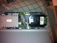

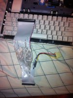
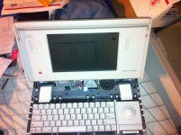
Its a little crude, but it works...
Please tell me you can recreate it as I need two
yes,
The wife and I are going to sit down and come up with a method of production.
Now that we have one working, and know exactly what to do to make it work.
This first one is going to hap. he's in desperate need.
The wife and I are going to sit down and come up with a method of production.
Now that we have one working, and know exactly what to do to make it work.
This first one is going to hap. he's in desperate need.
1) Get two pieces of wood the appropriate lengths . . .
. . . with enough extra to clamp it to the work surface if you can still get the connector on the clamp end into your vise.
2) Epoxy headers and a MOLEX receptacle in the perfect positions on one board.
3) Make a slitting diagram on the second piece of wood with enough room to staple or clamp the ends of your ribbon cable at the ends.
4) Make slots in a piece of cardboard to mark the cable appropriately, with holes to register it over pins in the slitting board
Then do your wire slitting at one workstation . . .
. . . mount your IDCF connectors on the headers on the other workstation . . .
. . . do your cable fabrication/temporary punchdown & soldering . . .
. . . remove the fab jig . . .
. . . do your final punchdown on the vise . . .
Bonus points for setting up the boards/jigs at comfortable angles on a larger assembly jig the width of your table with the vise bolted to one side that hangs off the end of the table for bolt clearance. If you don't want to/can't clamp the production station board to the table, just make it enough larger to use 1x2 stock to make a rim/frame to fit around the table and pile a couple of cinder blocks on top during production . . .
Dunno . . . just off the top of my head . . .
. . . with enough extra to clamp it to the work surface if you can still get the connector on the clamp end into your vise.
2) Epoxy headers and a MOLEX receptacle in the perfect positions on one board.
3) Make a slitting diagram on the second piece of wood with enough room to staple or clamp the ends of your ribbon cable at the ends.
4) Make slots in a piece of cardboard to mark the cable appropriately, with holes to register it over pins in the slitting board
Then do your wire slitting at one workstation . . .
. . . mount your IDCF connectors on the headers on the other workstation . . .
. . . do your cable fabrication/temporary punchdown & soldering . . .
. . . remove the fab jig . . .
. . . do your final punchdown on the vise . . .
Bonus points for setting up the boards/jigs at comfortable angles on a larger assembly jig the width of your table with the vise bolted to one side that hangs off the end of the table for bolt clearance. If you don't want to/can't clamp the production station board to the table, just make it enough larger to use 1x2 stock to make a rim/frame to fit around the table and pile a couple of cinder blocks on top during production . . .
Dunno . . . just off the top of my head . . .
the wife is color coding them for me
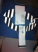
I find either way you do it, making these is quite time consuming.
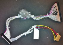
revision #4
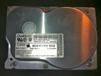
Also, with this 72gb u320 2.5" drive project i have been working on.
Managed to pull the 700mb Quantum out of my PM 6100 and install the new kind.
anyways looking at the original 40mb Conner HD it says +12 250ma / +5 275ma
Well this 700mb drive from the PM 6100 says +12 210ma / +5 200ma
So I would assume this newer more energy friendly drive would be a good choice.
takes the wife 20 min to color code
takes me about 1:20 to solder all the wires on
Also this thread I installed a SCSI Internal ZIP 100mb, seems to work out good.
viewtopic.php?f=10&t=21236
Also, with this 72gb u320 2.5" drive project i have been working on.
Managed to pull the 700mb Quantum out of my PM 6100 and install the new kind.
anyways looking at the original 40mb Conner HD it says +12 250ma / +5 275ma
Well this 700mb drive from the PM 6100 says +12 210ma / +5 200ma
So I would assume this newer more energy friendly drive would be a good choice.
takes the wife 20 min to color code
takes me about 1:20 to solder all the wires on
Also this thread I installed a SCSI Internal ZIP 100mb, seems to work out good.
viewtopic.php?f=10&t=21236
I didn't realize you were cutting and splicing every wire until I saw the color coding piccie. Why did you decide to splice the connections rather than rearranging the uncut wires on the IDC34F side?
because hap is going to sell these on ebay, and I need the IDC's to be solid, those idc are mechanically designed to be crimped to a cable not cut wires.
I don't want some big monkey fingers ripping out the wires after the first day.
I don't want some big monkey fingers ripping out the wires after the first day.
just i just thought of a good idea??
What if i epoxy'd the IDC's together after I pop the wires on?? hummmmm
no doubt popping the wires on the 34 pin side would be easier!
What if i epoxy'd the IDC's together after I pop the wires on?? hummmmm
no doubt popping the wires on the 34 pin side would be easier!
No need, folks have been reworking ribbon cables on existing harnesses for as long as IDC has been around. I you're going into production, just buy new connectors and ribbon cable. Get the three part connectors with the double-back strain relief setup. I missed you request for a new graphic, I'll work on that, as well as a diagram for an assembly jig setup.
I've got some time, the major hacks are at the awaiting parts acquisition stage again. : I'll do a diagram before I do the 'ole Scrooge MacDuck dive into the 21" high pile of 1400s. Gotta prune that back to a reasonable height of unborken lids attached to tricked out books . . .
. . . and a pile of spare parts for distribution. }
I've got some time, the major hacks are at the awaiting parts acquisition stage again. :
I'll do a diagram before I do the 'ole Scrooge MacDuck dive into the 21" high pile of 1400s. Gotta prune that back to a reasonable height of unborken lids attached to tricked out books . . .. . . and a pile of spare parts for distribution. }
Great!
Sounds good.

Sounds good.
I just did a local upload of the scanned doodle so I can print it out at work and muck it out a bit after I get back from dinner.
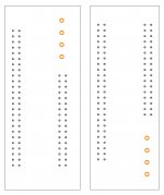
For the time being, I'm pretty happy with this cable.
Got some bigger shrink tube at harbor freight This one I made today, turned out pretty decent.
edit:
last one for the night.
Got some bigger shrink tube at harbor freight This one I made today, turned out pretty decent.
edit:
last one for the night.
HEH!! }
That one looks a lot more presentable, uni,
That one looks a lot more presentable, uni,
nice!, is that a fuse in there?
THX, uni, it went a bit easier than I'd thought it might. This is the first time I've done the criss-cross on opposite layers.
I think it's a resistor to limit the Termination Power current, but it might be something else, gotta figure that out from the boards I've now got in hand.
p.s. can you click to get the full size image? It usually takes a while before I can view the full size.
I think it's a resistor to limit the Termination Power current, but it might be something else, gotta figure that out from the boards I've now got in hand.
p.s. can you click to get the full size image? It usually takes a while before I can view the full size.
is the full size image 700+ x 1150 + ?
Sounds right, I cleared my cache and now I can see it too. I figured as much, when I place attachments, I'll have to be careful about how I do it or clear my cache. I'm guessing that previews are a no-no.
If anyone spots a boo-boo, lemme know.
If someone wants to critique the layout, PLEASE do!
If someone knows how to add an LED activity circuit, that'd be very cool, I'll add it in.
If anyone knows the right component for the TERMPWR jumper circuit, I'll add that info into the diagram as well.
If someone wants to make a production file for Seeeding some boards, I'd be thrilled, I want a pair!
Like I said on the first page, this would make a great community project! :approve:
I especially like the notion of doing a mounting sled for laptop drives or a board that'll easily bolt up to a 2.5" SCA adapter. For the former, I've got an APS external 2.5" HDD case. For the latter there are several permutations to consider.
I can't imagine that the little SCA Drives we've been playing with and a tiny muffin fan could possibly use as much power as the big honking OEM drives. :?:
If anyone spots a boo-boo, lemme know.
If someone wants to critique the layout, PLEASE do!
If someone knows how to add an LED activity circuit, that'd be very cool, I'll add it in.
If anyone knows the right component for the TERMPWR jumper circuit, I'll add that info into the diagram as well.
If someone wants to make a production file for Seeeding some boards, I'd be thrilled, I want a pair!
Like I said on the first page, this would make a great community project! :approve:
I especially like the notion of doing a mounting sled for laptop drives or a board that'll easily bolt up to a 2.5" SCA adapter. For the former, I've got an APS external 2.5" HDD case. For the latter there are several permutations to consider.
I can't imagine that the little SCA Drives we've been playing with and a tiny muffin fan could possibly use as much power as the big honking OEM drives. :?:
The 2.5" SCA drives draw too much power.
Some of the full size more modern hd's 800mb - 1gb consume less power then the 40mb Connor.
(As in my above post) the modern drives are quieter.
I just realized there might not be enough room in that area for a patch pcb,
so off the bat it would have to be kind of like the sca adaptors,
where the pcb pops right on to the hard drive and the 30 pin cable would make the whole stretch to the adaptor.
I suppost you could make 2 revisions, SCSI 2.5, SCSI 3.5,
Then one could just use a standard PC-Floppy cable to connect the PCB.
well they would have to hack of the end that flips pins for floppy 2.
Some of the full size more modern hd's 800mb - 1gb consume less power then the 40mb Connor.
(As in my above post) the modern drives are quieter.
I just realized there might not be enough room in that area for a patch pcb,
so off the bat it would have to be kind of like the sca adaptors,
where the pcb pops right on to the hard drive and the 30 pin cable would make the whole stretch to the adaptor.
I suppost you could make 2 revisions, SCSI 2.5, SCSI 3.5,
Then one could just use a standard PC-Floppy cable to connect the PCB.
well they would have to hack of the end that flips pins for floppy 2.
Interesting, how far over budget are the SCA drives?
I've got the 50 pin connector flopped to the other side of the board on the layout. If I'm looking at the correctly, a 3.5" HDD will plug into the bottom of the adapter just like the SCA Drives do and the IDC34 cable will plonk onto their headers behind that in the same manner.
I've got the info for putting the 40 pin 2.5" SCSI drive socket opposite the 50 pin connector. I'll do that so the 2.5" drive will plug into the "other bottom" of the adapter exactly like the 2.5" SCA drives do.
Only one adapter PCB to adapt either type of drive, as necessary.
Dunno if it'll work . . . I'll play with it in the AM . . . |)
I've got the 50 pin connector flopped to the other side of the board on the layout. If I'm looking at the correctly, a 3.5" HDD will plug into the bottom of the adapter just like the SCA Drives do and the IDC34 cable will plonk onto their headers behind that in the same manner.
I've got the info for putting the 40 pin 2.5" SCSI drive socket opposite the 50 pin connector. I'll do that so the 2.5" drive will plug into the "other bottom" of the adapter exactly like the 2.5" SCA drives do.
Only one adapter PCB to adapt either type of drive, as necessary.
Dunno if it'll work . . . I'll play with it in the AM . . . |)
well the original 40mb Connor hd is:
+12 - 250ma
+5 - 275ma
The IBM SCA Drive is
+12 - 800ma
+5 - 500ma
This newer scsi Quantum 700mb drive i have here is:
+12 - 210ma
+5 - 200ma
the 100mb scsi zip drive, witch works only because it does not use the 12v boost regulator just the +5v regulator
+5 - 800ma - but might still over heat the +5v regulator over time.
Yes to one PCB, -great idea Mr. Smarty pants. I have a 2.5 to 3.5 adaptor, but the power/data location config is non standard.
+12 - 250ma
+5 - 275ma
The IBM SCA Drive is
+12 - 800ma
+5 - 500ma
This newer scsi Quantum 700mb drive i have here is:
+12 - 210ma
+5 - 200ma
the 100mb scsi zip drive, witch works only because it does not use the 12v boost regulator just the +5v regulator
+5 - 800ma - but might still over heat the +5v regulator over time.
Yes to one PCB, -great idea Mr. Smarty pants. I have a 2.5 to 3.5 adaptor, but the power/data location config is non standard.
That's odd about the pinout, where did you get your 3.5"->2.5" Adapter? :?:
http://www.hardwarebook.info/SCSI_Internal_%282.5%22%29
There's power on both ends of that interface, did they lay out the connector out upside down or install the connectors backwards on the PCB? )
http://www.hardwarebook.info/SCSI_Internal_%282.5%22%29
There's power on both ends of that interface, did they lay out the connector out upside down or install the connectors backwards on the PCB?
) Very strange HDD mounting tray/setup in the Portable. Why the centerline mounting holes for the HDD? This is not convenient at all! :-/
)
On a more serious note: you'd probably want to slit the lines on a PC FDD cable to match the original cable. Apple l could have folded the ribbon cable. It's not just easier to route the way it's done, it might help to keep crosstalk at bay to jumble the wires about like that on the way to the HDD since there don't appear to be enough lines for the alternate ground line method . . .
. . . or just use the original cable!
) On a more serious note: you'd probably want to slit the lines on a PC FDD cable to match the original cable. Apple l could have folded the ribbon cable. It's not just easier to route the way it's done, it might help to keep crosstalk at bay to jumble the wires about like that on the way to the HDD since there don't appear to be enough lines for the alternate ground line method . . .
I dont think corss-talk is going to be a concern @ 1.5mb / sec, or across 5 inches of cable 
Apple wasn't concerned with cross-talk with the original portable hd cable design, not sure why you would mention it now.
The 2.5 to 3.5" adaptor
I got it on ebay.
Apple wasn't concerned with cross-talk with the original portable hd cable design, not sure why you would mention it now.
The 2.5 to 3.5" adaptor
I got it on ebay.
I mentioned crosstalk on the first page of the thread and now I'm wondering about it again. The original cable is slitted and done up in a double ponytail deal with wire ties making one full twist overall. That's likely way better than a straight ribbon cable in terms of crosstalk, so they might have been thinking in those terms. I'm trying to cover all angles so I'm thinking out loud here in .TXT . . .
. . . and kidding around in retaliation for that "Mr. Smarty pants" crack.
Got linkage to that adapter?
. . . and kidding around in retaliation for that "Mr. Smarty pants" crack.
Got linkage to that adapter?
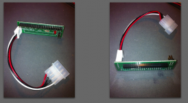
I just figured out how to convert a Cheap@$$ 3.5"->2.5" IDE converter to a Luggable 2.5" SCSI cable! ;D
1) Desolder the edge mounted IDC headers for the 3.5" connection.
2) Solder the slitted PC FDD cable's stripped ends to the proper positions on the "edge card connector" where the headers were.
4) Mount it off the end of the SCSI HDD's headers so that the old 2.5" IDE P & G connection sockets hang in the air.
The cheap SCA->50pin 3.5" SCSI connectors can probably be converter as well.
1) Bake & shake all the components off the board.
2) Lop the ends, both MOLEX and jumper headers, off the PCB.
3) Install a straight soldertail IDC50 plug opposite where the male connector was.
2) Solder the slitted PC FDD cable's stripped ends into the proper thru-hole positions for the SCA connector.
I'll have to complete the diagram I did to figure out the SCSI Voodoo of the SCA adapters to give you the "pinout" for the FDD wires.
I'm not sure that this will work physically, but it appears that the board is narrow enough to fit below the roof. Someone else is going to have to test it.
If I damage the stickers, it'll void the warranty on my Luggable's perfectly serviceable Hard Disk 40SC.
1) Desolder the edge mounted IDC headers for the 3.5" connection.
2) Solder the slitted PC FDD cable's stripped ends to the proper positions on the "edge card connector" where the headers were.
4) Mount it off the end of the SCSI HDD's headers so that the old 2.5" IDE P & G connection sockets hang in the air.
The cheap SCA->50pin 3.5" SCSI connectors can probably be converter as well.
1) Bake & shake all the components off the board.
2) Lop the ends, both MOLEX and jumper headers, off the PCB.
3) Install a straight soldertail IDC50 plug opposite where the male connector was.
2) Solder the slitted PC FDD cable's stripped ends into the proper thru-hole positions for the SCA connector.
I'll have to complete the diagram I did to figure out the SCSI Voodoo of the SCA adapters to give you the "pinout" for the FDD wires.
I'm not sure that this will work physically, but it appears that the board is narrow enough to fit below the roof. Someone else is going to have to test it.
If I damage the stickers, it'll void the warranty on my Luggable's perfectly serviceable Hard Disk 40SC.
i just got this aztechmonster thing to work,
its pretty cool, quite fast, uses almost no power.
Hap made this really great mounting plate with his CNC machine. Makes a flawless fit in the portable.
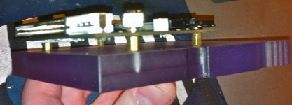
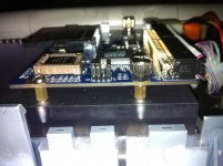
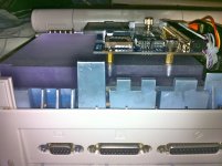
its pretty cool, quite fast, uses almost no power.
Hap made this really great mounting plate with his CNC machine. Makes a flawless fit in the portable.
not to thread jack, but the portable has a VGA connection?
Nope, IIRC it has a video out port to which very little has ever been attached or used for anything all that useful.
http://support.apple.com/kb/TA45501?viewlocale=en_US :-/
Nice adapter, uni! 1/2" or 3/4" Plexi? I was looking at doing a simplified sheet metal bracket, the one in the Luggable is just stupid!
http://support.apple.com/kb/TA45501?viewlocale=en_US :-/
Nice adapter, uni! 1/2" or 3/4" Plexi? I was looking at doing a simplified sheet metal bracket, the one in the Luggable is just stupid!
Well looks like he may have started out with 3/4 but milled it down, it fits snugly in place,
it snaps right into place with same snaps that hold in the stock HD.
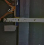
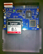
it snaps right into place with same snaps that hold in the stock HD.
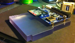
looks like hap is starting to sell them.
A 34pin to 50pin SCSI adaptor/cable /w molex connector
http://www.ebay.com/itm/Macintosh-Portable-M5120-M5126-Custom-34-to-50-pin-Adaptor-Cable-SCSI-HD-/151059342613?pt=US_Drive_Cables_dapters&hash=item232bd6a515
A 34pin to 50pin SCSI adaptor/cable /w molex connector
http://www.ebay.com/itm/Macintosh-Portable-M5120-M5126-Custom-34-to-50-pin-Adaptor-Cable-SCSI-HD-/151059342613?pt=US_Drive_Cables_dapters&hash=item232bd6a515
PCB time.
yeah, i think a pcb would be fantastic!
This is as good a project as I can think of for me to learn to do files for Seeeding some boards. :approve:
What's the best demo PCB design tool for small boards or least expensive small board license for a commercial tool for Mac or PC/Win7/Ubuntu? Mac preferably, but I've always gone to the platform with the correct tool for the job instead of the other way around.
What's the best demo PCB design tool for small boards or least expensive small board license for a commercial tool for Mac or PC/Win7/Ubuntu? Mac preferably, but I've always gone to the platform with the correct tool for the job instead of the other way around.
Check out Osmond PCB. I've been using it since it was beta back in 2000 or thereabouts. All of my printed circuit designs, ANS CPU adapter, Beige G3 ROM, IIfx RAM, have been done with Osmond and the Gerber files output from there.
http://www.osmondpcb.com/index.html
The free download will let you do any design and layout that the paid version will, but you won't be able to output your design to Gerber or Postscript files if it has more than 700 pins. Pins are inflection points (and ends?) to traces.
So small designs can be done for free and output for fabrication. Large designs can be made for free, but one must buy the software in order to output a file for fabrication.
Scroll down on the "Download" page for legacy versions, including a System 8.1 PPC version.
Do the tutorial.
You can create and edit parts in Osmond, for example the 64 pin SIMM connector for the IIfx RAM, and the Mac II ROM modules. Designing is much easier if you first create the parts. Then layout the parts in your design, create a rats nest of connections, and then route the rats nest into a usable board.
I did not find the auto-routing to be very good, but I have not tried it again since 2001. It may have improved.
http://www.osmondpcb.com/index.html
The free download will let you do any design and layout that the paid version will, but you won't be able to output your design to Gerber or Postscript files if it has more than 700 pins. Pins are inflection points (and ends?) to traces.
So small designs can be done for free and output for fabrication. Large designs can be made for free, but one must buy the software in order to output a file for fabrication.
Scroll down on the "Download" page for legacy versions, including a System 8.1 PPC version.
Do the tutorial.
You can create and edit parts in Osmond, for example the 64 pin SIMM connector for the IIfx RAM, and the Mac II ROM modules. Designing is much easier if you first create the parts. Then layout the parts in your design, create a rats nest of connections, and then route the rats nest into a usable board.
I did not find the auto-routing to be very good, but I have not tried it again since 2001. It may have improved.
I was looking at my Luggable and the Conner HDD's board to cable connection looks kinda funky. Is it a hardwired/soldered inter-board cable connector setup or a RA male-female header pin type deal?
yup the hd 34 pin IDC connector is soldered to the PCB.
I'm looking into butchering (key-slotting one side) of a 40/80 PATA cable to plug into the Luggable's 34pin header connector. It's a question of length, whether or not all the lines are implemented a/o the MoBo connector is plugged or set up for VCC on pin 20.
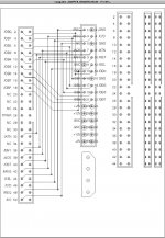
Looks promising. Rounded ones are available! [] ]'>
Looks promising. Rounded ones are available! [
] ]'>
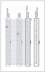
Interesting prospect, ugly, but possible. Playtime at work. [}
] ]'>nice!
I'm thinking a short, round, single device cable with VCC on pin 20 instead of a plug. I'll be looking into the slave/master section of dual cables, but that's looking iffy. Half the key needs to be cut away in any configuration. Cutting it off entirely and reversing the connector may be necessary for the dual device end, but it looks like you can't plug it in backwards after the connector is notched any which way. The battery plug and edge of the chassis act as a keying mechanism. [] ]'>
] ]'>. . . way too ugly! Besides, I think my PCB layout got badly borked when I flipped a component around. About the time I relaxed about the cabling problem and girded for a re-do of the PCB connections, it hit me. I HATE soldering, so the notion of building TWO custom cables using standard IDC methodology and reducing the connector count on the PCB to zero finally dawned on me as the most simple of possible adaptations! [ ] ]'>
Has anyone with a Luggable got an old school floppy cable for the PC handy, the kind that still has edgecard connectors alongside the header interfaces?
Card edge connectors fit fine in the space underneath the HDD, but will the connector with ribbon cable folded over fit under there? It doesn't need to slide under, it only needs to be possible to set it in place and install the HDD above it. The adapter PCB will be parallel to the HDD, the 34 and 50 pin edgecard connector cables on either side of the adapter PCB act as standoffs and strain relief.
If someone could check the fit for me I'd appreciate it, It'll take me a week to figure where I've hidden my old PC cables.
If this approach works out, the only soldering necessary will be the four leads from the MOLEX Connector to the adapter PCB. [}] ]'>
Besides, I think my PCB layout got badly borked when I flipped a component around. About the time I relaxed about the cabling problem and girded for a re-do of the PCB connections, it hit me. I HATE soldering, so the notion of building TWO custom cables using standard IDC methodology and reducing the connector count on the PCB to zero finally dawned on me as the most simple of possible adaptations! [] ]'>Has anyone with a Luggable got an old school floppy cable for the PC handy, the kind that still has edgecard connectors alongside the header interfaces?
Card edge connectors fit fine in the space underneath the HDD, but will the connector with ribbon cable folded over fit under there? It doesn't need to slide under, it only needs to be possible to set it in place and install the HDD above it. The adapter PCB will be parallel to the HDD, the 34 and 50 pin edgecard connector cables on either side of the adapter PCB act as standoffs and strain relief.
If someone could check the fit for me I'd appreciate it, It'll take me a week to figure where I've hidden my old PC cables.
If this approach works out, the only soldering necessary will be the four leads from the MOLEX Connector to the adapter PCB. [}
] ]'>My question is the pic with the black resistor looking thing is that is really needed?? Also on the 34 pin connector does pins 2,6,11,and 16 need to be grounded?? If not I can just cut those off then I suppose.. Thanks for any help!!! Matt
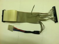
Thanks for any help!!! Mattpretty sure those need to be grounded bud.
yes those have to be grounded or the cable will not work.
i think it would be better to attach them to the corresponding spot on the IDC,
be careful with the 50pin side, once you get it working i would epoxy the wires to the IDC because they are quite fragile when you put the wires in the idc like that. even if you have the additional strain relief, you still should put some epoxy or something for a greater mechanical/electrical connection, reliability. Or else you will have a monkey fingers day and rip the wires right out of the 50pin IDC.
i think it would be better to attach them to the corresponding spot on the IDC,
be careful with the 50pin side, once you get it working i would epoxy the wires to the IDC because they are quite fragile when you put the wires in the idc like that. even if you have the additional strain relief, you still should put some epoxy or something for a greater mechanical/electrical connection, reliability. Or else you will have a monkey fingers day and rip the wires right out of the 50pin IDC.
also pin 26 on the 50 pin connector side, I leave term pwr disconnected.
On the pic earlier in the post with the black resistor thingy.. that's the image I used.. what ground should 2,6,11,and 16 be grounded to?? The set of pins 27,28,29, and 30?? Or is there a pin they should point to on the 50 pin?? I don't see a ground on the 50 pin.. just the set for the power on 27,28,29,30
Matt
Matt
Well our friend in Japan who makes the AztecMonster boards is making the cables.. fyi...
http://www.ebay.com/itm/MacPortable-34pin-general-50pin-SCSI-Conversion-Cable-New-condition-/301061945939?pt=US_Vintage_Computing_Parts_Accessories&hash=item4618b0ba53#ht_305wt_880
Matt
http://www.ebay.com/itm/MacPortable-34pin-general-50pin-SCSI-Conversion-Cable-New-condition-/301061945939?pt=US_Vintage_Computing_Parts_Accessories&hash=item4618b0ba53#ht_305wt_880
Matt
That's a pretty steep price for a cable.
Judging from the picture, though, it looks like it's very well made.
I find Uniserver's to be more than adequate, though (if not somewhat less polished, but who's going to see it anyway?)
c
Judging from the picture, though, it looks like it's very well made.
I find Uniserver's to be more than adequate, though (if not somewhat less polished, but who's going to see it anyway?)
c
well i made quite a few for hap. did the one he sent you look like this one?

because that is pretty much how the final revision looks.
because that is pretty much how the final revision looks.
Yeah, it looks a lot like that.
I made a slight modification, though; I took a utility knife and trimmed the ribbon cable at the 34 pin end so that it's flush with the connector.
How much do you sell these for?
c
I made a slight modification, though; I took a utility knife and trimmed the ribbon cable at the 34 pin end so that it's flush with the connector.
How much do you sell these for?
c
well i sell them to hap for 45 each, and hap sells them for 120.00
I thought this might make things a bit easier. When I took apart my LC to install a second hard drive I saw this bugger. Soldering wires to this would seem really easy to do from a 34 wire ribbon.
Just my 2 cents.
Just my 2 cents.
but then how will you install your HD into your poor LC now?
Well its back in the LC. But these are not hard to find. I may pick up a one and try. Just need my portable to work first! But I would also like to mount the drive in another Mac to check contents too.
hot diggity dogggggggggggg
[attachment=0]Screen Shot 2014-01-18 at 9.50.23 AM.png[/attachment]
[attachment=0]Screen Shot 2014-01-18 at 9.50.23 AM.png[/attachment]
yeah its gotta be done this way. for various reasons and possible variables.
this way its the most compatible…
I suggest installing a SCSI2SD with it. for the portable.
http://www.codesrc.com/mediawiki/index.php?title=SCSI2SD

I should soon be able to distribute this
and the SCSI2SD, as long as i get the ok from mike.
I think he deserves a royalty per item sold.
this way its the most compatible…
I suggest installing a SCSI2SD with it. for the portable.
http://www.codesrc.com/mediawiki/index.php?title=SCSI2SD
I should soon be able to distribute this
and the SCSI2SD, as long as i get the ok from mike.
I think he deserves a royalty per item sold.
Love it Uni!!! Nice... I'm sure I will be buying some!!!! Also the Japanese guy last time I checked was selling the 34 to 50 pin cables on ebay.. not sure if they are still there.. I assume they are..