

Thread
BlueCI

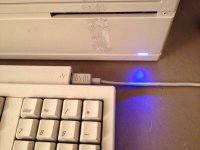
To me the Blue LED reminds me of the beginning of the (LED) revolution. It's quite refreshing to see.
i want to convert mine to high intensity red led's my cracked case IIci is going to get some fun !
olePigeon always comes up with the best ideas!
I really like that LC I Mod you did, Floppy+optical drive+Hard drive = freakin' cool!
that IIci stripe is also cool!
i want to convert mine to high intensity red led's my cracked case IIci is going to get some fun !
olePigeon always comes up with the best ideas!
I really like that LC I Mod you did, Floppy+optical drive+Hard drive = freakin' cool!
that IIci stripe is also cool!
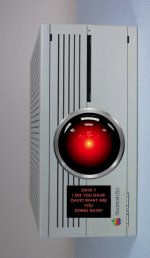
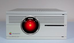
It would be very interesting to see a HAL-eye on the front of a IIci or Q700, maybe have the strobing controlled by hard disk activity or audio output. Somewhere I remember seeing/having an old screensaver that replicated the control panels from the movie under OS 8, but I could be wrong. 
CelGen: I don't care much for bright blue LEDs, either. It seems to me to have been something of a fad during the last 12 years or so.
Idea: Maybe make it white, like modern Macs? It would be a little easier on the eyes.
Case in point: I have some Macally External HD enclosures, and the bright blue power indicator makes an excellent nightlight! I could almost read by it if I wanted!!
Enough ranting now.
c
Idea: Maybe make it white, like modern Macs? It would be a little easier on the eyes.
Case in point: I have some Macally External HD enclosures, and the bright blue power indicator makes an excellent nightlight! I could almost read by it if I wanted!!
Enough ranting now.
c
I believe 2001 space odyssey was like the 13th best film? I thought i saw that some where.
i'm not emotional at all when it comes to movies, but that part where he is "killing" Hal9000 is pretty darn sad
Hal 9000 should of had a directive programmed into it, that made it not able to hurt humans on his side.
i'm not emotional at all when it comes to movies, but that part where he is "killing" Hal9000 is pretty darn sad
Hal 9000 should of had a directive programmed into it, that made it not able to hurt humans on his side.
HAL probably did, and no matter what, sometimes a computer just becomes corrupt for no reason, and, in the case of HAL, such corruption can have deadly consequences.
Dave probably did the best thing possible for HAL: shut him down (in effect, "killing" him), because he (it?) had a confused mind and couldn't think straight anymore.
Anyway, back on topic (at least for me):
A multi colored LED sounds interesting. If the thing had a sleep mode (I'm sure someone will do it someday), perhaps it could change color (say, from white to amber) to indicate the machine is asleep.
Meanwhile, my opinion is to keep it simple for now. A single color LED is much easier to just plunk in (since the circuit is designed for such a device anyway).
c


I don't have a IIci so can't do some of the leg work on this, but the Guide to the Macintosh Family Hardware documents bit 0 of register A of VIA1 as "reserved". This bit is pin 2 of VIA1, and should connect to the diagnostic edge connector with a pull-up.
The II, IIx, and SE/30 are documented to have 3 bits (0-2) of that register as "reserved" as well, also going to the edge connector. I've got a small control panel that toggles that bit and controls an LED on the IIx.
So, if you can find the VIA1 and get to pin 2 whether it's the edge connector or the pin or whatever, that can be used to control the LED from software.
Thanks to my multimeter and some advice from bbraun, I can confirm the IIci brings out pin 2 of VIA1 to pin 7 of the diagnostic edge connector with a 100k pullup to +5V. For people really interested, the 100k pull-up resistor is R110 on the bottom of the board near the edge connector. The edge connector pins are labeled 1 through 15 on the top side of the motherboard, so you'll be looking for pin 7.
I just tested his control panel and it does in fact control whether that edge connector pin is outputting 5V or 0V. So with that you could definitely control something. As you point out, an RGB LED is going to need more control pins than 1, but it's a start!
You're right that you need 3 bits, but even then, as a digital I/O you're only going to get 8 possible colors. Each of the R, G, and B can be either on or off. To do a ton of different colors you have to control the intensity of each of the 3 colors which would require something like PWM, which would be a bad idea to implement in software in this case IMO. I wonder if there's a 1-wire PWM controller IC that could do it for you.
I just tested his control panel and it does in fact control whether that edge connector pin is outputting 5V or 0V. So with that you could definitely control something. As you point out, an RGB LED is going to need more control pins than 1, but it's a start!
You're right that you need 3 bits, but even then, as a digital I/O you're only going to get 8 possible colors. Each of the R, G, and B can be either on or off. To do a ton of different colors you have to control the intensity of each of the 3 colors which would require something like PWM, which would be a bad idea to implement in software in this case IMO. I wonder if there's a 1-wire PWM controller IC that could do it for you.
You do this: Connect some sort of circuitary to the single pin, then use some software to switch it on and off in a sequence dpendant on the colour required (more on this below). Data transmission rates could be slow, but then it's only going to change once every few seconds anyway.
To send the signal, you could do something like this:
-We need six colours
-To encode this we need 4 bits
-To send this we switch the signal on and off like in a serial cable.
So, for example, to display orange (colour 3 in the logo), you would send: 1 start bit, 4 data bits: 0011, 1 stop bit. (Actually, you could even drop the stop bit.) Then you just need some sort of circuit to decode that. A slow rate of even something like 2 bits per second would be enough.
Or, alternatively, you could just send a single pulse, and have the hardware remember what colour it's displaying, and thus decide on the next one.
Or, even better (sorry, I had a brain surge), you could (although this would need a higher bps rate and possibly a microcontroller at the other end) even send something like 4 or even 8 bits for each colour, so something like this: 1 start bit, 8 data bits for DAC conversion to Red component, 8 data bits for DAC conversion to Green component, 8 data bits for DAC conversion to Blue component, 1.5 stop bits. (It would be advisable to include an easily recognisable stop bit signal, otherwise the system might hang waiting for a missed signal.)
To send the signal, you could do something like this:
-We need six colours
-To encode this we need 4 bits
-To send this we switch the signal on and off like in a serial cable.
So, for example, to display orange (colour 3 in the logo), you would send: 1 start bit, 4 data bits: 0011, 1 stop bit. (Actually, you could even drop the stop bit.) Then you just need some sort of circuit to decode that. A slow rate of even something like 2 bits per second would be enough.
Or, alternatively, you could just send a single pulse, and have the hardware remember what colour it's displaying, and thus decide on the next one.
Or, even better (sorry, I had a brain surge), you could (although this would need a higher bps rate and possibly a microcontroller at the other end) even send something like 4 or even 8 bits for each colour, so something like this: 1 start bit, 8 data bits for DAC conversion to Red component, 8 data bits for DAC conversion to Green component, 8 data bits for DAC conversion to Blue component, 1.5 stop bits. (It would be advisable to include an easily recognisable stop bit signal, otherwise the system might hang waiting for a missed signal.)
You can use the single pin as a serial control line driving a simple 8 bit triple-channel PWM MCU.
But in that case, the MCU can run by itself and control the LED by itself.
But using the single line as a serial databus, HDD activity and everything could be monitored via the LED controller (Given that you have a proper OS Driver to handle it all of course..)
But in that case, the MCU can run by itself and control the LED by itself.
But using the single line as a serial databus, HDD activity and everything could be monitored via the LED controller (Given that you have a proper OS Driver to handle it all of course..)
Having one blink out "Yes, sir! May I have another!" in multi-hued Morse code every time you insert a floppy would be awesome! 
On a practical level: analog circuit interpretation of speaker output for controlling brightness and hue might just work without additional processor time for the Mac or need for a MicroController.
For a Mac with stereo speaker output, that could be two channel variable music-mood lighting right the and there! }
Startup BONG!!!!!! would be VERY interesting that way.
jt = creature of the Analog/Neolithic Era . . . :-/
edit: bonus points for utilizing a readily available vacuum tube or three into the circuit! [] ]'>
On a practical level: analog circuit interpretation of speaker output for controlling brightness and hue might just work without additional processor time for the Mac or need for a MicroController.
For a Mac with stereo speaker output, that could be two channel variable music-mood lighting right the and there! }
Startup BONG!!!!!! would be VERY interesting that way.
jt = creature of the Analog/Neolithic Era . . . :-/
edit: bonus points for utilizing a readily available vacuum tube or three into the circuit! [
] ]'>