

Since the previous post, I found that changing the HV caps HAD NOT after all eliminated the startup problems. So, as foreshadowed, I next changed the caps on the small daughterboard.
The board is about the size of a large postage stamp and stands vertically off the main PCB, connected by 10 through-hole soldered pins. To tackle this, I waited till I had received a better desoldering iron I had ordered - one with the heated hollow tip that goes over the pin to be desoldered, with a hand-compressed piston that is released for a one-shot solder suck. It can be used one-handed, which is good when needing to hold something steady. This iron worked perfectly, clearing each pin and hole of solder on first shot.
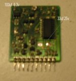
The two SMD electrolytic caps are the same type as the ones we generally replace on the logic boards. I snipped them off, then thought about taking a photograph. Sorry the image is blurred - I didn't notice until too late after I had soldered it back into place.
The chip is a dedicated switch-mode power controller, managing the Pulse-Width Modulation and other timing functions for the switching circuits that determine voltages delivered by the PSU under various conditions, including the startup trickle current. The board also has a tiny trimpot, which I didn't touch. Much of the surface of this board was blackened and a bit sticky - I could not clean it fully with alcohol, acetone, or detergent, and did not want to scrape off the insulating lacquer, so left if looking fairly smutty once it was clean enough to check carefully for any broken or burnt traces. I found none.
Looking from the component side, pins down, the cap on the left is 100uf x 6.3volt, negative side down. The cap on the right is 33uf x 25volt, negative to right. Unlike the main PCB, the sub-board carries no markings to identify locations or show the polarity of caps, so it is important to NOTE the polarity of the caps before removing them.
I cleaned up the pads with a bit of flux, then used spots of solder paste on the new components, holding them in place with tweezers while flowing with a sharp pointed iron.
With these two caps replaced, the PSU behaved perfectly - that is to say it did not start immediately on power-up, and it responded correctly to the soft-power switches on the back of the IIsi and on the keyboard.
I have a full set of replacements for all remaining electrolytics, but will hold them in reserve until there is failure.
For reference, the full list of eletrolytic caps on the main PCB is:
C101,C102 220uf x 250v (primary)
C105 4.7uf x 400v (replaced) (primary)
C202,C203 2200uf x 6.3v (secondary)
C211,212 1200uf x 16v (secondary)
C302 56uf x 35v (primary)
C401,C402 100uf x 25v (secondary)
Rick
The board is about the size of a large postage stamp and stands vertically off the main PCB, connected by 10 through-hole soldered pins. To tackle this, I waited till I had received a better desoldering iron I had ordered - one with the heated hollow tip that goes over the pin to be desoldered, with a hand-compressed piston that is released for a one-shot solder suck. It can be used one-handed, which is good when needing to hold something steady. This iron worked perfectly, clearing each pin and hole of solder on first shot.
The two SMD electrolytic caps are the same type as the ones we generally replace on the logic boards. I snipped them off, then thought about taking a photograph. Sorry the image is blurred - I didn't notice until too late after I had soldered it back into place.
The chip is a dedicated switch-mode power controller, managing the Pulse-Width Modulation and other timing functions for the switching circuits that determine voltages delivered by the PSU under various conditions, including the startup trickle current. The board also has a tiny trimpot, which I didn't touch. Much of the surface of this board was blackened and a bit sticky - I could not clean it fully with alcohol, acetone, or detergent, and did not want to scrape off the insulating lacquer, so left if looking fairly smutty once it was clean enough to check carefully for any broken or burnt traces. I found none.
Looking from the component side, pins down, the cap on the left is 100uf x 6.3volt, negative side down. The cap on the right is 33uf x 25volt, negative to right. Unlike the main PCB, the sub-board carries no markings to identify locations or show the polarity of caps, so it is important to NOTE the polarity of the caps before removing them.
I cleaned up the pads with a bit of flux, then used spots of solder paste on the new components, holding them in place with tweezers while flowing with a sharp pointed iron.
With these two caps replaced, the PSU behaved perfectly - that is to say it did not start immediately on power-up, and it responded correctly to the soft-power switches on the back of the IIsi and on the keyboard.
I have a full set of replacements for all remaining electrolytics, but will hold them in reserve until there is failure.
For reference, the full list of eletrolytic caps on the main PCB is:
C101,C102 220uf x 250v (primary)
C105 4.7uf x 400v (replaced) (primary)
C202,C203 2200uf x 6.3v (secondary)
C211,212 1200uf x 16v (secondary)
C302 56uf x 35v (primary)
C401,C402 100uf x 25v (secondary)
Rick