

Thread
ultimate SE/30
one of these graphics cards + video board mod for grey scale 
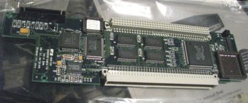
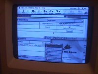
then of corse the PDS connector mod on the graphics card, so i can still have my maccon ethernet card
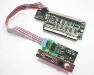
new fast HD! + one of max1zzz terminated SCA to 50 pin adaptors
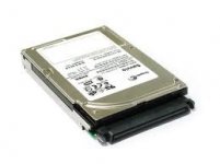
and to finish it off with 128megs of ram and a dougg3 ROM
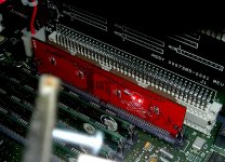
then of corse the PDS connector mod on the graphics card, so i can still have my maccon ethernet card
new fast HD! + one of max1zzz terminated SCA to 50 pin adaptors
and to finish it off with 128megs of ram and a dougg3 ROM
You already perform the grayscale modification from which i posted the info on what to do?
Oh wow... is that the standard compact mac resolution on the internal 9"?
You have it made? Wow congrats.
Wow, I think I missed that earlier discussion, very nice! How did you connect the Pivot card to the internal CRT?
Sorry NO, have not made it yet.
And no, that is not the stock resolution on that picture of that CRT… that resolution is 640x480 - greyscale, the image is from a SE/30.
The IIsi video card to ==> CRT (Video board) is not figured out yet.
I just got my video cards today! SO LET THE MODDING BEGIN
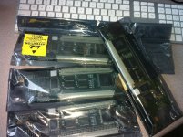
And no, that is not the stock resolution on that picture of that CRT… that resolution is 640x480 - greyscale, the image is from a SE/30.
The IIsi video card to ==> CRT (Video board) is not figured out yet.
I just got my video cards today! SO LET THE MODDING BEGIN
Holy cow that is amazing. Looks like I'm gonna have to keep an eye out for such a card within a reasonable price range.
The amount of recent successful DIY projects/hacks/mods is amazing.
The amount of recent successful DIY projects/hacks/mods is amazing.
I remember the time I hacked the bottom off another SE/30 and increased another by that height. Sculpted and painted the bottom to another. Made a perfect bay for a CD drive install. Worked very well too! Kept the motherboard on the bottom, so some new cabling was required to get around the CD drive. I traumatized many Macs as a child...
Crap, now I want one of those cards.
Oh, on the ultimate SE/30 You forgot the soft-standby power modification!
edit: You know, come to think of it. I dont think I ever finished it.. CRAP. I knew i forgot about that. I know the OS hack was done to allow the VIA pin to be toggled on shutdown/powerup.
Oh, on the ultimate SE/30 You forgot the soft-standby power modification!
edit: You know, come to think of it. I dont think I ever finished it.. CRAP. I knew i forgot about that. I know the OS hack was done to allow the VIA pin to be toggled on shutdown/powerup.
lol you should totally finish it.
you should buy one they are only $2.99
http://www.ebay.com/itm/Radius-Color-Pivot-IIsi-Video-Interface-Card-Apple-Mac-/151117999850?pt=US_Vintage_Computing_Parts_Accessories&hash=item232f55aeea
you should buy one they are only $2.99
http://www.ebay.com/itm/Radius-Color-Pivot-IIsi-Video-Interface-Card-Apple-Mac-/151117999850?pt=US_Vintage_Computing_Parts_Accessories&hash=item232f55aeea
Yea I need to. I was going to try and modify the original Sony power supply that way I can maintain standby 5V, whilst the rest is switched. The simplest method is use a relay on the mains, and use the PRAM batt to power the standby circuit. But, naa...
I was going to use a small microcontroller attached to the power supply, the VIA, and ADB port that way when you pressed power it would fire up the machine. And when you hit shutdown, it cuts out the power supply.
I didnt realize how cheap those cards are. So i just purchased one. However I gotta figure out how to make that fit. Luckily it uses the standard euroDIN/nubus connectors, So any type of expansion board would work. Only problem is, How to make sure the card stays Primary instead of secondary all the time, even on a lost-PRAM bootup. What i might do is connect the two sources together via Mux, and switch the internal CRT from either source.
I guess the other option is remove the on-board DeclROM, so it just disables the internal all the time.
I was going to use a small microcontroller attached to the power supply, the VIA, and ADB port that way when you pressed power it would fire up the machine. And when you hit shutdown, it cuts out the power supply.
I didnt realize how cheap those cards are. So i just purchased one. However I gotta figure out how to make that fit. Luckily it uses the standard euroDIN/nubus connectors, So any type of expansion board would work. Only problem is, How to make sure the card stays Primary instead of secondary all the time, even on a lost-PRAM bootup. What i might do is connect the two sources together via Mux, and switch the internal CRT from either source.
I guess the other option is remove the on-board DeclROM, so it just disables the internal all the time.
As far as getting it to "fit"
http://www.ebay.com/itm/GENERIC-96-PIN-MALE-EUROCARD-DIN-CONNECTORS-3-pcs-/171027189841?pt=LH_DefaultDomain_0&hash=item27d203d051
I can pull the original right-angle Eurocard/Din connector off and replace it with a streight one. This will allow the card to lay flat.
http://www.ebay.com/itm/GENERIC-96-PIN-MALE-EUROCARD-DIN-CONNECTORS-3-pcs-/171027189841?pt=LH_DefaultDomain_0&hash=item27d203d051
I can pull the original right-angle Eurocard/Din connector off and replace it with a streight one. This will allow the card to lay flat.
Techknight is back in business! Scratch that.. ROM simm will be in the way. grrr, maybe a riser board routed out in eagle with a couple of eurodins.
ok i got the video card to fit with the lid on.. and screws in…
i will have flip the heddar on the maccon card…
i will have flip/remove the db15 header on the video card
and i had to lop off a hunk of the pcb of the video card.
didn't look like there were any traces i think it was just dead space.
oh also no room for a floppy drive… but so what.. who needs a floppy?
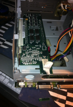
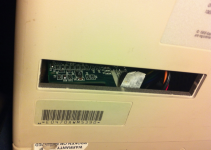
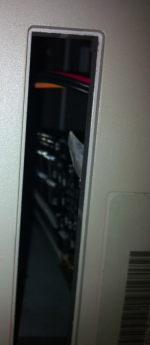
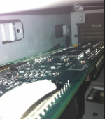
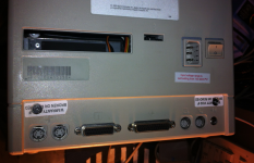
the way it is, the card fits snuggly into the ledge of the case, right there.. almost like that is the reason for the ledge!
and because my 2.5" hd solution is thin.. will be able to fit under the video card no problem!
i will have flip the heddar on the maccon card…
i will have flip/remove the db15 header on the video card
and i had to lop off a hunk of the pcb of the video card.
didn't look like there were any traces
i think it was just dead space.oh also no room for a floppy drive… but so what.. who needs a floppy?
the way it is, the card fits snuggly into the ledge of the case, right there.. almost like that is the reason for the ledge!
and because my 2.5" hd solution is thin.. will be able to fit under the video card no problem!
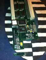
might not be kosher… but if it works… pretty cool!
Unfortunately that is a multilayer board. Looks like you wacked into the VCC and GND planes. You better hope it works
File that edge VERY carefully to a "V" profile until you can see the clean edges of each layer before firing it up! :O
Check out the flat stacking "wrong angle" adapter card hack.
Check out the flat stacking "wrong angle" adapter card hack.
its ok i bought 4.
i might smooth the edge with my dremel before i fire it up.
what makes you think VCC is there? looks like a bunch of dead pcb space to me.
unless you have the images of the pcb layers, it would be hard to tell what is there in the other layers
assuming its a 4 layer board.
looks like i am the first one to make it physically fit. Yay to me.
now i need to whip up pin to pin cable with an aui on the other end.
i might smooth the edge with my dremel before i fire it up.
what makes you think VCC is there? looks like a bunch of dead pcb space to me.
unless you have the images of the pcb layers, it would be hard to tell what is there in the other layers
assuming its a 4 layer board.
looks like i am the first one to make it physically fit. Yay to me.
now i need to whip up pin to pin cable with an aui on the other end.
Chances are at least the ground plane was running around the board. Might still work though, fingers crossed! If there are ground problems though you might be in for all kinds of weird behaviour...and none of us like that kind of stuff 
ill wrap some tinfoil around it it ill be fine haha
it ill be fine haha
Just put the tinfoil in your shorts if you're going to fire that thing up after using a Dremel Tool on it, you may need the protection. :
Use a flat bastard metal file to carefully shape the cut side of the board to a wedge shaped edge. You should be able to clearly see the ends of all layers (be they signal traces or big slabs of power or ground planes) cleanly sheared off on the edge of the FRP substrate like the layers of sedimentation on a Paleological Dig.
THEN clean it up and fire it up.
Use a flat bastard metal file to carefully shape the cut side of the board to a wedge shaped edge. You should be able to clearly see the ends of all layers (be they signal traces or big slabs of power or ground planes) cleanly sheared off on the edge of the FRP substrate like the layers of sedimentation on a Paleological Dig.
THEN clean it up and fire it up.
99 percent of the time, the inner layers contain the ground and VCC routes. Thats usually rule of thumb, although not always. But I have been rebuilding boards long enough to know that this is the case.
ok i will but first i have to make the db 15 cable… so where is pin one… and they are in order 1-15? seems to easy.
Yes they are, and they follow exactly pin-for-pin the DB15 layout of standard mac video.
So yeap, its that easy.
Trash:
If you file the edges as a V, I dont see why it wouldnt work. Just be careful, thats all Im sayin, although for 3 dollar video cards who cares, but 150 dollar ethernet cards, not so much. ;-)
BTW, Off topic: I wonder if LC PDS ethernet cards which are still plentiful, would work in an SE/30. Technically the PDS is the same. Well not the same pinning, but same architecture.
Thanks, and yep, that was my point in the main thread, the Riser and VidCard costs will remain negligible until we can get this to work in the SE/30. At that point demand will likely go up, etc . . .
It wouldn't surprise me too much if you could make an adapter to dot it. A lot would depend upon the address the LC cards use and whether it's available in the SE/30 spec/ROM. We know that NuBus Cards can be implemented in a SecondWave expansion box for the SE/30 where Apple never intended it to be. So why not an LC 10bT PDS Card adapter for the SE/30?
I'd start by checking the available drivers from all the usual prospects before taking a look at the hardware . . . if I could, that is.
:-/
Now my eyes went crosseyed, but it looks like the LC-PDS. The lower 96-pin portion of it can directly swap over to the SE/30. All the signals are the same, however the pinouts are ENTIRELY different so a remap PCB would be needed.
Only thing that i can see from a quick glance, is A28 to A30 arnt included in the lower PDS. Only the expanded PDS, whereas the SE/30 contains all address lines. Also the LC PDS contains a function code 3 (FC3) which the SE/30 doesnt have. But i dont think ethernet cards use this control pin. Also the LC only has /PDS.BG (bus grant), whereas the SE/30 has both a /PDS.BG and a /BG. No idea what impact this would have.
I believe that LC Ethernet cards, given a pinout-remap would directly swap over, They both map into Slotspace $E
Only thing that i can see from a quick glance, is A28 to A30 arnt included in the lower PDS. Only the expanded PDS, whereas the SE/30 contains all address lines. Also the LC PDS contains a function code 3 (FC3) which the SE/30 doesnt have. But i dont think ethernet cards use this control pin. Also the LC only has /PDS.BG (bus grant), whereas the SE/30 has both a /PDS.BG and a /BG. No idea what impact this would have.
I believe that LC Ethernet cards, given a pinout-remap would directly swap over, They both map into Slotspace $E
looks like I'm partially done with the video cable.i would assume pin one is the one to the outside of the card? Where the loped off bit is… i took the dremel to it… its nice and smooth.. more of rounded then v.
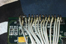
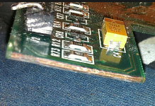
ill try it in there first.
not to worry i have 3 IIsi's one of them is crap and wouldn't care if it set fire
ill try it in there first.
ok got the cable done.
i guess whats left is to test this thing…..
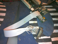
i guess whats left is to test this thing…..
ok good progress,
it works in the IIsi,
next up the se/30…
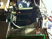
lol playing with my db15 2 vga adaptor gets some interesting results...
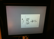
it works in the IIsi,
next up the se/30…
lol playing with my db15 2 vga adaptor gets some interesting results...