

Thread
Mac 128k help needed!
Hello everyone! I have a bit of a problem with my new Mac 128. Everything is beautiful on the inside and out but the issue with it is I'm getting that error code. Can someone help me pinpoint the trouble ram chip? I am experienced in soldering and I have sockets for new a new ram chip but the issue would be for me to get the chip and finding the one that's bad.
I am 17 and have quite a collection. So far I have 5 128k computers. A Lisa2 and multiple other se's plusses etc... And I fixed nearly all of them so I have a very good amount of knowledge on this kind of stuff.
I am also very happy this has the original logic board in it and 400k floppy which I wrestled to get working with parts from swore parts 400k drives.
Any help would be appreciated.
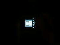
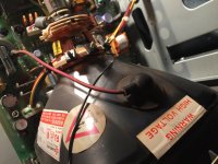
I am 17 and have quite a collection. So far I have 5 128k computers. A Lisa2 and multiple other se's plusses etc... And I fixed nearly all of them so I have a very good amount of knowledge on this kind of stuff.
I am also very happy this has the original logic board in it and 400k floppy which I wrestled to get working with parts from swore parts 400k drives.
Any help would be appreciated.
Alright thanks so much for the help! I really appreciate it! Would you know off hand what location that is on the motherboard?
Thanks again for your help
Thanks again for your help
Ya... G... 11.... 
The board is marked. Just like playing Battleship!
The board is marked. Just like playing Battleship!
Oh haha I see it now I didn't know there was letters on the side like that.
Thanks so much for your help! I really appreciate you taking the time to help me out!
Thanks so much for your help! I really appreciate you taking the time to help me out!
Here's a pic of the board. There isn't any visual defects with it. I guess it needs to be replaced. Does the ram chip have to be the same brand as all the others? I am pretty sure that type of thing is important on some computers.
Now I'm wondering where I am going to find a replacement chip.
I will have to talk to my friend and see if he has a spare one.
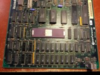
Now I'm wondering where I am going to find a replacement chip.
I will have to talk to my friend and see if he has a spare one.
Does not have to be the same brand, just the same type. While I have not experienced it myself, others report that the Apple-Logoed RAM chips seem to fail at a pretty high rate. If I recall, you can still buy new RAM chips for pretty cheap from electronic parts distributors.
Yes I remember reading about that also. And probably if I replace this one I heard that it has the possibility of giving me another error code from another bad chip that the test wasn't even able to get to yet. I will let you know what I am able to find once it is replaced.
Thanks again for your help this is fun and interesting to solve this problem!
Thanks again for your help this is fun and interesting to solve this problem!
Best to buy a small handful just in case that happens. 
MT is the manufacturer for Apple who I forget who that is; their RAM Chip is the 4264; which is pretty generic of the 4164 Dynamic RAM Chip. You should be able to use 4164s in its place. Get as many as you can of them, preferable all 16. Take your time soldering them as they are sensitive to heat and static. And the traces are delicate in this area, so take your time and take it easy doing this. Many would replace the chips with sockets and then put the RAM Chips into the sockets.
If you like or are daring, you can upgrade at this point by using 41256 Dynamic RAM chips and it will boost your board to become a 512K Mac, its a direct chip drop in and no need to cut or add wires to the board. But that is on you, if you do, you need to replace all 16 RAM Chips.
If you like or are daring, you can upgrade at this point by using 41256 Dynamic RAM chips and it will boost your board to become a 512K Mac, its a direct chip drop in and no need to cut or add wires to the board. But that is on you, if you do, you need to replace all 16 RAM Chips.
Wow thanks for everyone helping me on this! I didn't realize I would get this kind of support from people. I looked on eBay and saw they are $6 a piece :-/ http://pages.ebay.com/link/?nav=item.view&alt=web&id=381024802658
I have removed the ram on these before but I used hot air and small screwdrivers to pry them out. I guess a solder sucker would be better to use although all I have is wick.
Another problem I worry about is getting solder to the other side of the motherboard connecting it to the top half. With a socket I can't reach the top traces to get connected to the legs.
I would like to keep it original 128k ram. I can't believe that they are $6 a piece.
I have removed the ram on these before but I used hot air and small screwdrivers to pry them out. I guess a solder sucker would be better to use although all I have is wick.
Another problem I worry about is getting solder to the other side of the motherboard connecting it to the top half. With a socket I can't reach the top traces to get connected to the legs.
I would like to keep it original 128k ram. I can't believe that they are $6 a piece.
Uniserver has the RAM to redo 128K and 512K machines. Send him a PM.
Since its a 4-layer board, using a heatgun and solder wick would be a nightmare with enormous risk, but doable nonetheless.
Since its a 4-layer board, using a heatgun and solder wick would be a nightmare with enormous risk, but doable nonetheless.
If you are using hot air, you should be using solder paste instead of solder on a roll. Simply done, fill the hole with solder paste and put the chip in and apply heat with a 15 watt iron and then inspect it. Clean up with acetone and alcohol when you're done.
There is a metal grommet in the hole that connects to traces on both sides of the board, but you should clean up the holes before soldering in the chips. A 15 watt iron, some flux and solder wick should clean the hole throughly. A clean hole will make the solder flow evenly to both sides. Add a bit of flux to the hole and solder from the bottom pin side and not the top chip side and let gravity and capillary action pull the solder down.
In my day, 4164s used to be $35 a piece and that price did not go down until after 1994!
There is a metal grommet in the hole that connects to traces on both sides of the board, but you should clean up the holes before soldering in the chips. A 15 watt iron, some flux and solder wick should clean the hole throughly. A clean hole will make the solder flow evenly to both sides. Add a bit of flux to the hole and solder from the bottom pin side and not the top chip side and let gravity and capillary action pull the solder down.
In my day, 4164s used to be $35 a piece and that price did not go down until after 1994!
Alright with a socket I wouldn't be able to solder from the chip side anyway.
It am going to need to find a good way to remove these without damaging the traces. I have a good iron and flux but I can borrow things from my uncle. What do you think is the best tool to remove these chips with?
It am going to need to find a good way to remove these without damaging the traces. I have a good iron and flux but I can borrow things from my uncle. What do you think is the best tool to remove these chips with?
i am going to be a little delayed on Replies I am helped cover the pool.
I am going to be a little delayed on Replies I am helping cover the pool now.
Just fyi my 128 showed ram issue code but ram has not proven to be the issue.
Oh god.
I inspected the motherboard and I don't see any visual bad spots.
I am done helping cover the pool so I can talk again.
I am going to try and re-seat the rom chips and see if there is a change.
I inspected the motherboard and I don't see any visual bad spots.
I am done helping cover the pool so I can talk again.
I am going to try and re-seat the rom chips and see if there is a change.
Ok reseating the Rom chip didn't help.
The startup bong doesn't sound healthy which makes me think the only source could be ram.
I have these 16 pin sockets which I can use on it.
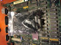
The startup bong doesn't sound healthy which makes me think the only source could be ram.
I have these 16 pin sockets which I can use on it.
If you have the radioshack desoldering tool (one of the few things they ever got right!), you can remove the chips quickly without ruining the traces. You just have to add a little solder to the joint with the bulb pressed and when the solder joint liquifies, release the bulb and the solder comes right out. It takes a little practice to use it but once you got it down, this would only take 40 minutes to unsolder all the chips at a few seconds per pin. Then you clean the board and inspect the traces.
Wow that sounds awesome! I will have to get one of those! I will be able to use it for future things as well.
Thanks for the tip!
Thanks for the tip!
Thanks for the tip! I just ordered one and I will let you guys know how it goes! It looks super useful!
I have another 2 boards also that I think are toast.
I have another 2 boards also that I think are toast.
those things are difficult to work with, youll wear your thumb out quickly. Plus the tip isnt plated so it will fail in short order.
ive had many of those, never again. Then I got a hakko 808. Best thing ever...
ive had many of those, never again. Then I got a hakko 808. Best thing ever...
Oh great... Well it was cheep and I guess it will get the job done for just 1 chip that's all I need it to do (I hope)
I use them all the time. Its matter of practice. I'm sure there are Youtube videos out there on how to use it. It would take too long how to describe it here. But once you got it down pat, its simple.
Yeah I watched a video on YouTube of someone using one. It shouldn't be that hard to do. I hope
Should I use flux with it?
Should I use flux with it?
Famous last word ^^^^
Always is harder than it looks on your first few tries. I've destroyed a few parts practicing. Thankfully junk electronics (old TV after you zap the CRT or old VCR) are common.
Always is harder than it looks on your first few tries. I've destroyed a few parts practicing. Thankfully junk electronics (old TV after you zap the CRT or old VCR) are common.
Ok I will practice on a junk analog first.
Thanks for the advice
Thanks for the advice
Ok I will practice on a junk analog first.
Thanks for the advice
Thanks for the advice
Ok I will practice on a junk analog first.
Thanks for the advice
Thanks for the advice
yup i think i still have like 800 4164's -samsung.
i find that apple logo'd ram is the worst.
you should change them all.
i personally don't like sockets and don't see a need for them.
Once you change all the ram with some high quality samsung ram or equivalent,
the need to change ram in there will be something of the past.
The stuff apple threw in there was crap.
I also don't like upgraded 128k's, if you want 512k ram.. then get a 512k.
( but that is just me ) its your puter, its much more collectable stock.
especially an original Macintosh Mobo like that one.
Also, just adding higher density ram to a 128k, upgrading it to a 512k is not just a Drop in solution… You need a mux and some other parts, and a trace has to be cut as well.
I didn't check the link, was the that a bulb solder sucker?
As Elfin said, if you add solder to all 16 pins and then get your iron in there and get that solder nice and melted all the way through the porthole.
once you pop it, it should slurp up that pretty good., afterwards you might want to take some needle nose and rotate each leg of the ram, because
there might still be some slight soldered surfaces.
The nice thing about a desoldering iron is you can rotate while you are pulling the trigger and it sucks all the solder out really well.
Makes the task, much less labourous. Witch if you decided to change all 16 chips… is quite a task indeed.
if you just change that one chip.. you will be ok for a few weeks or months… until the next one goes bad too.
then you will be doing this all over again. Hopefully by then you have not misplaced all your supplies.
If anyone is interested in a owning a pretty good all-in-one desoldering iron, There is a pretty decent one on ebay for like 100 bucks free shipping.
http://www.ebay.com/itm/S-993A-110V-90W-Electric-Vacuum-Desoldering-Pump-Solder-Sucker-Gun-/161413419282?pt=LH_DefaultDomain_0&hash=item2594fd5112
I own it and its pretty decent. I like my hakko fr-300 much better, but those are 3x more. If you can get a Hakko 808, They are the Beastliest of all of them…
i think. But even those have went up in price.
the hakko 808 with its V Twin Vacuum pumps on the end there. ITs like a mini Harley engine.
i find that apple logo'd ram is the worst.
you should change them all.
i personally don't like sockets and don't see a need for them.
Once you change all the ram with some high quality samsung ram or equivalent,
the need to change ram in there will be something of the past.
The stuff apple threw in there was crap.
I also don't like upgraded 128k's, if you want 512k ram.. then get a 512k.
( but that is just me ) its your puter, its much more collectable stock.
especially an original Macintosh Mobo like that one.
Also, just adding higher density ram to a 128k, upgrading it to a 512k is not just a Drop in solution… You need a mux and some other parts, and a trace has to be cut as well.
I didn't check the link, was the that a bulb solder sucker?
As Elfin said, if you add solder to all 16 pins and then get your iron in there and get that solder nice and melted all the way through the porthole.
once you pop it, it should slurp up that pretty good., afterwards you might want to take some needle nose and rotate each leg of the ram, because
there might still be some slight soldered surfaces.
The nice thing about a desoldering iron is you can rotate while you are pulling the trigger and it sucks all the solder out really well.
Makes the task, much less labourous. Witch if you decided to change all 16 chips… is quite a task indeed.
if you just change that one chip.. you will be ok for a few weeks or months… until the next one goes bad too.
then you will be doing this all over again. Hopefully by then you have not misplaced all your supplies.
If anyone is interested in a owning a pretty good all-in-one desoldering iron, There is a pretty decent one on ebay for like 100 bucks free shipping.
http://www.ebay.com/itm/S-993A-110V-90W-Electric-Vacuum-Desoldering-Pump-Solder-Sucker-Gun-/161413419282?pt=LH_DefaultDomain_0&hash=item2594fd5112
I own it and its pretty decent. I like my hakko fr-300 much better, but those are 3x more. If you can get a Hakko 808, They are the Beastliest of all of them…
i think. But even those have went up in price.
the hakko 808 with its V Twin Vacuum pumps on the end there. ITs like a mini Harley engine.
Wow thank you for all of this useful information! Yes I remember reading that Apple branded chips were horrible and I guess I will change all of them then.
Yes I want to keep this thing as original as possible so I'm debating if I shoud use the sockets I have or just put the chips in directly.
Sorry for the delayed response but I was in school.
I hope I'm able to remove all of these chips just using the radio shack tool I ordered.
Thanks for the advice on adding solder to the legs first also and moving them with a needle nose prior to removing. This will be very useful and probably save me a lot of stress.
Thank you everyone on this forum providing me with all of this info it's really interesting and fun learning about all of this stuff!
Yes I want to keep this thing as original as possible so I'm debating if I shoud use the sockets I have or just put the chips in directly.
Sorry for the delayed response but I was in school.
I hope I'm able to remove all of these chips just using the radio shack tool I ordered.
Thanks for the advice on adding solder to the legs first also and moving them with a needle nose prior to removing. This will be very useful and probably save me a lot of stress.
Thank you everyone on this forum providing me with all of this info it's really interesting and fun learning about all of this stuff!
Wow I just noticed my triple post :0 my apologies on that. It's difficult to be using a iPhone to do all of this stuff haha. I will try to not do that again
512K boards are easy to find, and most 128Ks ended up either having a 512K board installed or the RAM being swapped to accommodate 512K. Handy in 1985, not so much in 2014. Finding a 128K board in there means you have to keep it as one, but it sounds like you've already decided to do just that. These things are starting to become harder to find, and original boards even harder again.
Sockets will also devalue the board, so I would just stick with your standard chips. The best solution is to replace them all as they will continue to fail otherwise, but if you are happy to replace them if and as required, you should be fine.
Nice work!
Sockets will also devalue the board, so I would just stick with your standard chips. The best solution is to replace them all as they will continue to fail otherwise, but if you are happy to replace them if and as required, you should be fine.
Nice work!
Yes I prefer having the original amount of ram I was surprised when I opened it to see it was not upgraded with a 400k floppy.
Thanks for the advice. I guess I'll just replace all of the ram chps without the sockets to prevent any future issues with it.
Thanks for the advice. I guess I'll just replace all of the ram chps without the sockets to prevent any future issues with it.
Start with the bad chip first and then test the board and see if it works. If yes, then continue replacing the others. replace a couple at a time and test the board, this way if something happens you can check your work and do a fix before continuing. Nothing worse than replacing all the chips at once and end up with a Sad Mac and you do not know which ones are at fault. And take your time with it.
Recently I was working on a Raspberry Pi and its twin somebody decided to take their foot to them, crushing the USB Ports. I replaced the USB Port on one of them and it works fine, thing is, the Pis use Black Plastic USB Ports and I used White ports- which is a minor thing. But on the other Pi, I used have used too much solder and shorted out a pin or two on the Pi, though it booted up, it comes up with an error of "Overvoltage on Port 2" - one the USB Ports. The next day I desoldered the replacement USB port neatly, cleaned up the board, checked the USB traces to the chip and then put the removed replacement USB Port back in, being a little stingy with the solder this time. Now it works like the day it came out of the factory! I got these two Pis as a pair from Ebay for less than $20 each, including S/H. And they now got White Ports, LOL!
Lesson here? So solder wisely and only use enough solder to close the joint. Inspect you work on both sides and then continue to the next pin. For me, the I could only see one side of the Pi, but I left huge solder balls on each pin - a sign of too much solder used.
Recently I was working on a Raspberry Pi and its twin somebody decided to take their foot to them, crushing the USB Ports. I replaced the USB Port on one of them and it works fine, thing is, the Pis use Black Plastic USB Ports and I used White ports- which is a minor thing. But on the other Pi, I used have used too much solder and shorted out a pin or two on the Pi, though it booted up, it comes up with an error of "Overvoltage on Port 2" - one the USB Ports. The next day I desoldered the replacement USB port neatly, cleaned up the board, checked the USB traces to the chip and then put the removed replacement USB Port back in, being a little stingy with the solder this time. Now it works like the day it came out of the factory! I got these two Pis as a pair from Ebay for less than $20 each, including S/H. And they now got White Ports, LOL!
Lesson here? So solder wisely and only use enough solder to close the joint. Inspect you work on both sides and then continue to the next pin. For me, the I could only see one side of the Pi, but I left huge solder balls on each pin - a sign of too much solder used.
Wow that's really smart! Thanks for the awesome tip!
Hello everyone! While I'm waiting for the tools to fix the other 128k I have another 128k in need of attention. When I power this one on for the first 30 seconds to a minute or so it displays this pattern on the screen. Any ideas? I already replaced the caps with another questionable broken mac board and it started booting up quicker then it used to which took like 5 minutes to just not starting at all but it doesn't bong and boot when it's supposed to. Any ideas? I know jail bars mean bad ram but when it does boot it doesn't show any errors
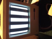
Also another thing to add is after the bars go away and the computer is warmed up I am able to restart it and have no problems.
It's just having trouble with the cold starts I don't know why.
All of my analog boards are working fine I make sure to test them with known working motherboard of a Mac plus.
Thanks everyone for all of your help!
It's just having trouble with the cold starts I don't know why.
All of my analog boards are working fine I make sure to test them with known working motherboard of a Mac plus.
Thanks everyone for all of your help!
Interesting. If it were an SE/30, it would be a RAM or broken trace issue. But since this is intermittent.... Hmmm... Page 65 of Dead Mac Scrolls says its a ROM Issue, probably after an upgrade.
Take out the board and with a chip remover or pencil and small flat head screw driver, loosen the ROMs and IWM chips (next to the ROM, if it is in a socket), wiggle them on the sockets and gently press them back in.
If it continues, then there is corrosion on the chips' pins. Remove the ROMs one and a time and with very fine Emory cloth, not Sandpaper - ask your hardware store for Emory Cloth, they know what it is, polish up the pins on the chips on both sides - the outside of the chip and the inside. Be gentle doing this so you don't bend a pin(s). Put ROM back in socket and do the other ROM and then the IWM Chip last.
After many years, sometimes the connections corrode over time and need to be cleaned up.
Take out the board and with a chip remover or pencil and small flat head screw driver, loosen the ROMs and IWM chips (next to the ROM, if it is in a socket), wiggle them on the sockets and gently press them back in.
If it continues, then there is corrosion on the chips' pins. Remove the ROMs one and a time and with very fine Emory cloth, not Sandpaper - ask your hardware store for Emory Cloth, they know what it is, polish up the pins on the chips on both sides - the outside of the chip and the inside. Be gentle doing this so you don't bend a pin(s). Put ROM back in socket and do the other ROM and then the IWM Chip last.
After many years, sometimes the connections corrode over time and need to be cleaned up.
Yes I have already cleaned the pins with a wire brush and gently brushed them.
The iwm isn't socketed.
I will try a set of roms From another board but I am pretty sure I tried that already.
I will let you know the results when I get home from school.
Thanks!
The iwm isn't socketed.
I will try a set of roms From another board but I am pretty sure I tried that already.
I will let you know the results when I get home from school.
Thanks!
Look at: https://68kmla.org/forums/index.php?/topic/23844-mac-plus-temporary-jailbar-screen/
Sounds to me like your Mac is not reaching its required voltage. Its either a part on the analog board or the caps going bad on the logic board, which is rare for a 128K. I forget which pins it is, maybe Uniserver or TechKight can post it, but you can check the voltage on the floppy port on the back of the Mac. If it registers less than 5.0 volts, you could get to the analog board and turn the potentiometer/variable resistor for 5 volts. Turn it a bit while it is off, turn on the machine and give it a while to come up and measure again. Turn off and adjust again as needed. It is better to be a bit over 5 volts, like 5.1 volts on your digital multimeter or the needle a tiny bit past the 5 volts mark on the analog meter. I use both.
If you still have this problem after adjusting, then its time to look at the analog board or the caps on the logic board.
Sounds to me like your Mac is not reaching its required voltage. Its either a part on the analog board or the caps going bad on the logic board, which is rare for a 128K. I forget which pins it is, maybe Uniserver or TechKight can post it, but you can check the voltage on the floppy port on the back of the Mac. If it registers less than 5.0 volts, you could get to the analog board and turn the potentiometer/variable resistor for 5 volts. Turn it a bit while it is off, turn on the machine and give it a while to come up and measure again. Turn off and adjust again as needed. It is better to be a bit over 5 volts, like 5.1 volts on your digital multimeter or the needle a tiny bit past the 5 volts mark on the analog meter. I use both.
If you still have this problem after adjusting, then its time to look at the analog board or the caps on the logic board.
I have already tried to adjust the voltage on the pot but no dice.
Sorry it's been so long since I posted on here I have lost steam on these things
But give me a few days and I'll get working on them again!
Sorry it's been so long since I posted on here I have lost steam on these things
But give me a few days and I'll get working on them again!
Time to get out the multimeter and start checking traces. With the exception of maybe 4 lines, all the lines on the 4264 RAM Chips are connected to their neighboring chips in parallel. So all the first row chips are connected together and all the second row chips are connected together and a majority of chips in Row 1 and Row 2 are connected to together.

This diagram shows that all but 2 or 4 pins should be connected together. Pins 2 (Data In), and 14 (Data out), with possibly Pins 4 (/RAS), and 15 (/CAS) should not be connected together. All the other pins should be connected. When they check out OK, follow the traces to the connected chips and test their connections with the multimeter. They should be OK.
Other than that, the only thing to do is to test the actual chips outside of RAM. I would guess following the suspected RAM Chip Data In/Out Lines to where they go and check their traces. If OK then those chips might be at fault. Without an oscilloscope it is hard to determine. Only Uniserver and/or TechKnight would be able to help out at this point.
This diagram shows that all but 2 or 4 pins should be connected together. Pins 2 (Data In), and 14 (Data out), with possibly Pins 4 (/RAS), and 15 (/CAS) should not be connected together. All the other pins should be connected. When they check out OK, follow the traces to the connected chips and test their connections with the multimeter. They should be OK.
Other than that, the only thing to do is to test the actual chips outside of RAM. I would guess following the suspected RAM Chip Data In/Out Lines to where they go and check their traces. If OK then those chips might be at fault. Without an oscilloscope it is hard to determine. Only Uniserver and/or TechKnight would be able to help out at this point.
Alright everyone I got the took in the mail today and it worked great! Well until I tried to remove the chip. The holes looked clear and has nothing in them but I couldn't get it out. So I took a Dremel and just cut the legs off of the chip. And then I desoldered everything individually.
Everything looked really nice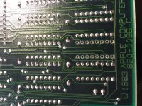
I didn't get any new chips from my friend yet so I decided to use some chips off of another dead 128 board. Since I didn't know the state of the chips that I removed I used a socket I plugged in a chip and it gave me a really weird chime. And then gave me this...
So I'm assuming I either need to get a known good ram chip or just scrap it now.
Thanks for any advice!
Everything looked really nice
I didn't get any new chips from my friend yet so I decided to use some chips off of another dead 128 board. Since I didn't know the state of the chips that I removed I used a socket I plugged in a chip and it gave me a really weird chime. And then gave me this...
So I'm assuming I either need to get a known good ram chip or just scrap it now.
Thanks for any advice!
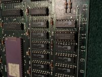
I've seen the non-Apple branded RAM chips for sale cheaper than what you have found them for BUT the electronics supply houses that I have seen them for sale in all have a minimum order requirement. I would have had to have bought dozens of them to meet the minimum and I have no use for that many. I found a 128k board on ebay Australia that had the RAM chips removed because at one point the owner wanted to do a homebrew 512k upgrade but never got around to it. I got the board and the original chips in a plastic bag shipped from New Zealand for like $100 and if you've seen shipping charges from Australia/NZ and what a complete 128k motherboard normally sells for you know that's cheap.
Oh wow that's a really good deal! I'm glad you were able to get that board working with all original chips!
Uniserver agreed to send me 20 chips for $25 including shipping.
I hope new chips will fix this boards issues.
Uniserver agreed to send me 20 chips for $25 including shipping.
I hope new chips will fix this boards issues.
Hi !
Just to add that the SAD MAC code 2 = Memory test - bus subtest
I think that adding a socket changes resistance, so you have to do it everywhere for the 16 chips. That may change voltage.....
Do you found a solution?
....
As I'm starting to do the same thing (one chip F5 is bad = error 04001) I have a decision to take, but I do not have the information needed:
My motherboard is a 128 second generation (design was the same as 512) only ram chips AND another chip AS253.
But I did not find any listing to be sure that all is correct..
Is there anyone knowing what to do for this upgrade?
My actual check list is:
Change 16 chips RAM
Add 1 chip AS253
Add 3 resist. R41,R41,R42
Add 1 C 51
Cut the W1
Is that anything?
Thanks a lot
PS: design of this card is 128K :630-0101 - 512K : 630-0118
Just to add that the SAD MAC code 2 = Memory test - bus subtest
I think that adding a socket changes resistance, so you have to do it everywhere for the 16 chips. That may change voltage.....
Do you found a solution?
....
As I'm starting to do the same thing (one chip F5 is bad = error 04001) I have a decision to take, but I do not have the information needed:
My motherboard is a 128 second generation (design was the same as 512) only ram chips AND another chip AS253.
But I did not find any listing to be sure that all is correct..
Is there anyone knowing what to do for this upgrade?
My actual check list is:
Change 16 chips RAM
Add 1 chip AS253
Add 3 resist. R41,R41,R42
Add 1 C 51
Cut the W1
Is that anything?
Thanks a lot
PS: design of this card is 128K :630-0101 - 512K : 630-0118