BIGMAC MMU
BIGMAC MMU
Macintosh · 1985 · PDF
| Filename | BIGMAC_MMU.pdf |
|---|---|
| Size | 0.30 MB |
| Year | 1985 |
| Subsection | prototypes / 1985_Big_Mac |
| Downloads | 3 |
Enjoying MacTrove?
Anonymous downloads are free and unlimited.
Create a free account to track favorites,
contribute metadata corrections, and join the
community chat.
Reader
Loading…
OCR / Text contents
Big Mac MMUSpeclflcation
Introduction:
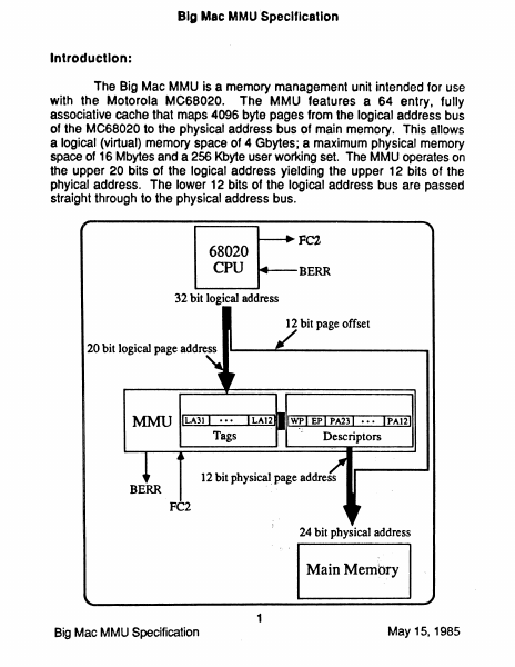
The Big Mac MMU is a memory management unit intended for use
with the Motorola MC68020. The MMU features a 64 entry, fully
associative cache that maps 4096 byte pages from the logical address bus
of the MC68020 to the physical address bus of main memory. This allows
a logical (virtual) memory space of 4 Gbytes; a maximum physical memory
space of 16 Mbytes and a 256 Kbyte user working set. The MMU operates on
the upper 20 bits of the logical address yielding the upper 12 bits of the
phyical address. The lower 12 bits of the logical address bus are passed
straight through to the physical address bus.
68020
CPU
BERR
32 bit logical address
12 bit page offset
20 bit logical page address ....- -..........- - - - - - - -...
12 bit physical. page address
BERR
24 bit physical address
Main Membry
1
Big Mac MMU Specification
May 15,1985
If the upper 20 bits of the logical address are contained in any of
the 64 entries in the MMU, the upper 12 bits of the physical address are
provided within 65ns. This permits the MMU to function without wait
states. If the page Is resident In the MMU. the access control bits
associated with that page are also checked to see H write protection and
or execute only protection is in effect.
If the upper 20 bits of the logical address are DQ1 contained in any
of the 64 entries in the MMU, a Bus Error (BERR) signal will be asserted.
This will suspend the execution of the instruction that caused the "miss",
and system software can then load the MMU with the correct physical
address of the page that caused the miss. The suspended instruction can
then be restarted. If the logical address is contained in the MMU and a
write protection or execute only protection violation is detected, a Bus
Error is also generated.
Ten 16 bit status registers are implemented within the MMU to
allow access to the following information: Page Accessed (status
registers 0 through 3 for use in generating LRU info), Page Dirty (status
registers 4 through 7), Exception Cause and MMU mode (status register 8)
and Logical Address Latch (status register 9).
Operation:
Supervisor and user states are defined by the function code 2 bit
(FC2) of the CPU (with FC2-=1 --> supervisor and FC2-=O _..> user).
The CPU and MMU combination operate with Supervisor state
addresses always unmapped. User state can operate either mapped (by
clearing the MODE bit in status register 8), or unmapped. The unmapped
state is entered by setting the MODE bit in register 8. In the unmapped
state the MMU presents logical address bits LA23 through LA 12 directly to
the physical address bits PA23 through PA12.
Independent of the mapping of User state, the registers of the MMU
are accessible for reading or writing ~ from Supervisor state.
The registers LARO through LAR63 (located at byte offsets $00000
through $3FOOO) contain the logical addresses of the 64 pages to be
mapped into the physical pages. The registers PARO through PAR63
(located at…
Showing first 3,000 characters of 8,464 total. Open the full document →