Classic Mac Tech Info
Classic Mac Tech Info
Macintosh · 2002 · PDF
| Filename | Classic_Mac_Tech_Info_2002.pdf |
|---|---|
| Size | 0.10 MB |
| Year | 2002 |
| Subsection | schematic |
| Downloads | 4 |
Enjoying MacTrove?
Anonymous downloads are free and unlimited.
Create a free account to track favorites,
contribute metadata corrections, and join the
community chat.
Reader
Loading…
OCR / Text contents
Classic Mac Tech Docs, v1.1: No warranties expressed or implied. Use at your own risk!
Classic Mac Tech Info
1.0 Introduction
Except for minor variations, the analog board for the Mac Plus described in this document
is the same as that used in earlier models (the 128K and 512K/512Ke), and contains the
horizontal, vertical, video and power supply circuits. The horizontal and video circuits are
also virtually identical to those used in the SE and SE/30, but the vertical and power supply circuits are completely different. As will be obvious from the schematics, the vertical
circuit in the classic machines makes sparse use of ICs, so it is a bit “partsy.” However, it is
a reliable design with no history of unusual problems. The power supply, on the other
hand, is notoriously prone to failure, as there is no fan inside the unit (Steve Jobs objected
to the noise, and preferred to risk overheating the machine instead).
2.0 Video Circuit
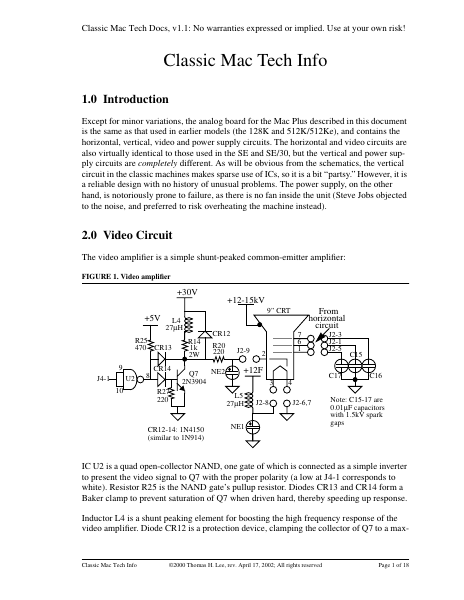
The video amplifier is a simple shunt-peaked common-emitter amplifier:
FIGURE 1. Video amplifier
+30V
+12-15kV
From
horizontal
circuit
9” CRT
+5V
L4
27µH
R25
470 CR13
9
U2
J4-1
10
8
CR14
CR12
R14
1k
2W
R20
220
NE2
Q7
2N3904
R27
220
CR12-14: 1N4150
(similar to 1N914)
J2-9
7
6
1
2
+12F
3
L5
27µH
J2-8
J2-3
J2-1
J2-5
C15
C17
4
J2-6,7
NE1
C16
Note: C15-17 are
0.01µF capacitors
with 1.5kV spark
gaps
IC U2 is a quad open-collector NAND, one gate of which is connected as a simple inverter
to present the video signal to Q7 with the proper polarity (a low at J4-1 corresponds to
white). Resistor R25 is the NAND gate’s pullup resistor. Diodes CR13 and CR14 form a
Baker clamp to prevent saturation of Q7 when driven hard, thereby speeding up response.
Inductor L4 is a shunt peaking element for boosting the high frequency response of the
video amplifier. Diode CR12 is a protection device, clamping the collector of Q7 to a max-
Classic Mac Tech Info
©2000 Thomas H. Lee, rev. April 17, 2002; All rights reserved
Page 1 of 18
Classic Mac Tech Docs, v1.1: No warranties expressed or implied. Use at your own risk!
imum of a diode drop above 30V, despite inductive kickback from L4, and even if some
CRT fault occurs. Resistor R20 limits the current under the latter fault condition.
The two neon bulbs act as voltage clamping devices to prevent serious overvoltages on the
filament and cathode terminals of the CRT. Similarly, the 1.5kV spark gaps integral with
C15-C17 act to protect the CRT under transient fault conditions.
Finally, inductor L5 provides ac isolation between the CRT and the 12V filament supply.
3.0 Horizontal Circuit
The high voltages in this circuit are all byproducts of horizontal deflection. The TTL-level
horizontal drive signal from the main logic board is inverted by open-collector NAND U2
(here connected as a simple inverter, with pullup resistor R26). The inverted signal then
feeds a small driver transistor Q6, whose output couples to the horizontal output transistor
Q3 through isolation tran…
Showing first 3,000 characters of 45,436 total. Open the full document →