
Yeah, I'm pretty sure that's what it's for. I can see the trace on the board (depicted in blue below) and verify it with my multimeter. It goes to R24, R25, the decoupling cap, and the the VCC pin of the flash chip. I don't know for sure if that's ALL it goes to, but it seems very likely. Here's a diagram I made of what's going on in that section of the board:
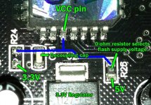
R25 supplies 5V and R24 supplies 3.3V. So you populate one of those two with a 0-ohm resistor (or a solder blob), leave the other unpopulated, and that brings the desired voltage to the flash chip. So for 3.3V flash compatibility I'm pretty sure all you have to do is move the 0 ohm resistor over to the 3.3V side (R24) instead of the 5V side (R25). I won't know for sure until I remove the 0 ohm resistor to make sure that completely isolates it from 5V, but that has to be what it's for.
R25 supplies 5V and R24 supplies 3.3V. So you populate one of those two with a 0-ohm resistor (or a solder blob), leave the other unpopulated, and that brings the desired voltage to the flash chip. So for 3.3V flash compatibility I'm pretty sure all you have to do is move the 0 ohm resistor over to the 3.3V side (R24) instead of the 5V side (R25). I won't know for sure until I remove the 0 ohm resistor to make sure that completely isolates it from 5V, but that has to be what it's for.