
Just to collate some info scattered around various threads and documents (this may be old news-- and hopefully I have this all correct):
Background
The standard compact Mac resolution of 512x342 uses 22.25kHz horizontal sweep and 60Hz vertical sweep. 22.25kHz = 44.93us per scan line, of which 32.68us is the main scan and 12.25us is the retrace period (per the Macintosh Family Hardware Reference). I found this to be a useful reference:
http://www.gradllc.com/images/HORIZONTAL.pdf
The basic idea is that the current through the yoke determines the resolution of the screen. A B&W CRT doesn't have any "dot pitch" per se, so if our focus is good enough we ought to be able to get any resolution we want. Except for the video signal itself, most of the voltages on the CRT are effectively DC, which is also convenient.
So if we want higher resolution, we need to figure out how to drive the yoke faster. To get to VGA, we need 31.5kHz. To drive a two-page display signal, we'd need about 68.5kHz. The vertical refresh for some of these resolutions may be higher too, but that's a much easier problem and can already be done with the onboard circuitry with just a few tweaks.
The big problem is that the horizontal yoke coli and the flyback transformer are part of the same resonant circuit, which is tuned to 22.25kHz and really doesn't like to run at any other frequency. There are a few components you can tweak to try to change the frequency tolerance, especially the flyback capacitor (C4 in the Plus, C12 in the SE series), but as techknight found in a much earlier thread, the performance still won't be very good.
Measurement
The current through the yoke is a sawtooth, but that's hard to measure directly without expensive equipment. instead, I took some measurements of the voltage on C4 on a Plus. What we expect to see is 0V for the main scan period then a big spike during the retrace period where the energy in the coil gets transferred to C4, while the beam is flying back from the right to left part of the screen. Here's what I found:
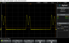
The flyback period is actually only 9.1us, even though the horizontal sync signal is low for 12.25us. But this is what we'd expect from a circuit like this. The retrace needs to be completely done before the HOT (Q3 on Plus, Q2 on SE) turns back on or the magic blue smoke might get out. The max voltage here is 168V, compared to a max rating of 400V for the transistor.
One thing that is odd is that the retrace is not a clean half-sine, but clearly shows two different frequencies superimposed. (This turned out to have interesting implications... more on that later.)
Background
The standard compact Mac resolution of 512x342 uses 22.25kHz horizontal sweep and 60Hz vertical sweep. 22.25kHz = 44.93us per scan line, of which 32.68us is the main scan and 12.25us is the retrace period (per the Macintosh Family Hardware Reference). I found this to be a useful reference:
http://www.gradllc.com/images/HORIZONTAL.pdf
The basic idea is that the current through the yoke determines the resolution of the screen. A B&W CRT doesn't have any "dot pitch" per se, so if our focus is good enough we ought to be able to get any resolution we want. Except for the video signal itself, most of the voltages on the CRT are effectively DC, which is also convenient.
So if we want higher resolution, we need to figure out how to drive the yoke faster. To get to VGA, we need 31.5kHz. To drive a two-page display signal, we'd need about 68.5kHz. The vertical refresh for some of these resolutions may be higher too, but that's a much easier problem and can already be done with the onboard circuitry with just a few tweaks.
The big problem is that the horizontal yoke coli and the flyback transformer are part of the same resonant circuit, which is tuned to 22.25kHz and really doesn't like to run at any other frequency. There are a few components you can tweak to try to change the frequency tolerance, especially the flyback capacitor (C4 in the Plus, C12 in the SE series), but as techknight found in a much earlier thread, the performance still won't be very good.
Measurement
The current through the yoke is a sawtooth, but that's hard to measure directly without expensive equipment. instead, I took some measurements of the voltage on C4 on a Plus. What we expect to see is 0V for the main scan period then a big spike during the retrace period where the energy in the coil gets transferred to C4, while the beam is flying back from the right to left part of the screen. Here's what I found:
The flyback period is actually only 9.1us, even though the horizontal sync signal is low for 12.25us. But this is what we'd expect from a circuit like this. The retrace needs to be completely done before the HOT (Q3 on Plus, Q2 on SE) turns back on or the magic blue smoke might get out. The max voltage here is 168V, compared to a max rating of 400V for the transistor.
One thing that is odd is that the retrace is not a clean half-sine, but clearly shows two different frequencies superimposed. (This turned out to have interesting implications... more on that later.)