
I did the early measurements on a Plus but I've done my experimentation on an SE/30 analog board. I found someone selling an analog board with a dead flyback transformer, which was perfect since I don't need it on the yoke driver anyway. Tomorrow I'll see if I can put together a useful schematic, but here's a picture in the meantime. It's a bit of a crude hack still:
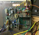
It takes three voltages to run the yoke board:
* 5V or the logic (U1),
* 12V for the base driver circuitry for Q2; that's the yellow wire attached to one end of R17 which has been lifted from the rest of the board
* A higher voltage, value TBD, to drive the horizontal coil itself. This will be instead of the step-up circuit involving the flyback transformer, CR3 and C13. That voltage comes in on the orange wire behind the yoke connector.
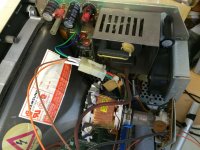
In the above photo the yoke is hooked up to the board for testing. (The blue wire is connected to the collector of Q2 for monitoring the voltage during retrace.) Eventually I split the horizontal and vertical coils, leaving the vertical coil connected to the analog board and running the horizontal coil to the modified yoke board:
More later...
It takes three voltages to run the yoke board:
* 5V or the logic (U1),
* 12V for the base driver circuitry for Q2; that's the yellow wire attached to one end of R17 which has been lifted from the rest of the board
* A higher voltage, value TBD, to drive the horizontal coil itself. This will be instead of the step-up circuit involving the flyback transformer, CR3 and C13. That voltage comes in on the orange wire behind the yoke connector.
In the above photo the yoke is hooked up to the board for testing. (The blue wire is connected to the collector of Q2 for monitoring the voltage during retrace.) Eventually I split the horizontal and vertical coils, leaving the vertical coil connected to the analog board and running the horizontal coil to the modified yoke board:
More later...