
So the plan is to disconnect the horizontal coil on the yoke from the main analog board and connect it to a new drive circuit which does the same thing. The first goal is just to get a decent image on the screen with these two separate circuits, which should prove the concept. Then it will be a lot easier to change the yoke driver, because all the flyback transformer circuitry will be eliminated.
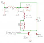
Here's the schematic of the yoke driver made from a modified SE analog board.
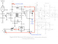
An here's how the modification works on the board-- greyed out components were either removed or are now unconnected, where red is for new connections. (C12 is wrong in the image below-- it should be .033, not .003)
For testing I drove it with a signal matching the frequency and duty cycle of the logic board HSYNC. Here's a plot of the result, powered from Vcc = 20V. Green is the voltage at the base of Q2, yellow is at the collector of Q2.
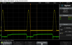
The height of the yellow pulse scales linearly with the supply voltage (about 230V here). Without the flyback it's a much simpler circuit, and now we get a nice clean half-wave rather than the ringing waveform in the full analog board circuit.
Here's the schematic of the yoke driver made from a modified SE analog board.
An here's how the modification works on the board-- greyed out components were either removed or are now unconnected, where red is for new connections. (C12 is wrong in the image below-- it should be .033, not .003)
For testing I drove it with a signal matching the frequency and duty cycle of the logic board HSYNC. Here's a plot of the result, powered from Vcc = 20V. Green is the voltage at the base of Q2, yellow is at the collector of Q2.
The height of the yellow pulse scales linearly with the supply voltage (about 230V here). Without the flyback it's a much simpler circuit, and now we get a nice clean half-wave rather than the ringing waveform in the full analog board circuit.