Home Documents Macintosh Turbo Mac Hardware Memory Map
Turbo Mac Hardware Memory Map

Turbo Mac Hardware Memory Map

Macintosh · 1984 · PDF
FilenameTurbo_Mac_Hardware_Memory_Map_19841017.pdf
Size0.97 MB
Year1984
Subsection prototypes / 1984_Turbo_Mac
Downloads5
Enjoying MacTrove? Anonymous downloads are free and unlimited. Create a free account to track favorites, contribute metadata corrections, and join the community chat.
Reader
Turbo Mac Hardware Memory Map
/
Loading…
OCR / Text contents
CONFIDENTIAL ------------------------------------------ CONFIDENTIAL 
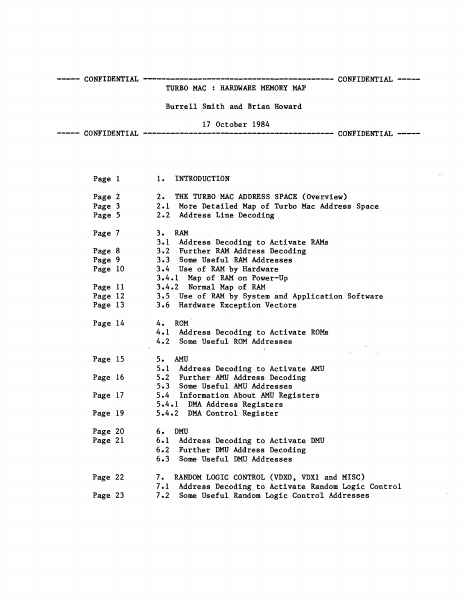
TURBO MAC : HARDWARE MEMORY MAP Burrell Smith and Brian Howard 17 October 1984 CONFIDENTIAL ------------------------------------------ CONFIDENTIAL INTRODUCTION Page 1 1. Page 2 Page 3 Page 5 2. THE TURBO MAC ADDRESS SPACE (Overview) 2.1 More Detailed Map of Turbo Mac Address Space 2.2 Address Line Decoding Page 7 3. RAM 3.1 Address Decoding to Activate RAMs Page 8 Page 9 Page 10 3.2 Further RAM Address Decoding 3.3 Some Useful RAM Addresses 3.4 Use of RAM by Hardware 3.4.1 Map of RAM on Power-Up 3.4.2 Normal Map of RAM 3.5 Use of RAM by System and Application Software 3.6 Hardware Exception Vectors Page 11 Page 12 Page 13 Page 14 4. 4.1 4.2 Page 15 Page 16 Page 17 Page 19 Page 20 Page 21 Page 22 Page 23 ROM Address Decoding to Activate ROMs Some Useful ROM Addresses AMU Address Decoding to Activate AMU Further AMU Address Decoding Some Useful AMU Addresses 5.4 Information About AMU Registers 5.4.1 DMA Address Registers 5.4.2 DMA Control Register 5. 5.1 5.2 5.3 6. 6.1 6.2 6.3 DMU Address Decoding to Activate DMU Further DMU Address Decoding Some Useful DMU Addresses 7. RANDOM LOGIC CONTROL (VDXO, VDXl and MISC) 7.1 Address Decoding to Activate Random Logic Control 7.2 Some Useful Random Logic Control Addresses Turbo Mac Memory Map 17 October 1984 Page 24 Page 25 Page 26 Page 27 Page 28 Page 29 Page 30 Page 31 8. SCC 8.1 Address Decoding to Activate SCC 8.2 Further SCC Address Decoding 8.3 Some Useful SCC Addresses 9. IWM 9.1 Address Decoding to Activate IWM 9.2 Further IWM Address Decoding 9.3 Some Useful IWM Addresses 10. VIA 10.1 Address Decoding to Activate VIA 10.2 Further VIA Address Decoding 10.3 Some Useful VIA Addresses 10.4 Turbo-Mac-Specific Information about VIA Registers 10.4.1 Port A Input, Output, and Data Direction Registers 10.4.2 Port B Input, Output, and Data Direction Registers 10.4.3 Control Registers 10.4.4 Interrupt Flag and Enable Registers Page 32 11. AUTO-VECTOR "READ" ADDRESSES Page 33 12. SOME USEFUL DECODING EQUATIONS Previous Document Versions: 1. Page 1 19-5ep-84, 10-Sep-1984. INTRODUCTION 
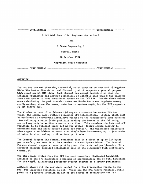
The principle portions of Turbo Mac's address space consist of volatile read/write memory (RAM) and permanent read-only memory (ROM). In addition to RAM and ROM, several input/output functions are also selected using address lines, so that they appear to occupy portions of the Turbo Mac "memory". These include the 6522 Versatile Interface Adapter (VIA), the 8530 Serial Communications Chip (SCC), the disk interface chip (IWM), the Address Management Unit (AMU), the Data Management Unit (DMU) , and the Random Logic Control. When the Turbo Mac is first turned on, ROM appears at the bottom (lowest addresses) portion of the address space. This is useful for the ROM-stored software which starts the system running. After startup, the OVERLAY signal from the VIA is changed to a low (zero), mapping RAM into its normal place at the bott…

Showing first 3,000 characters of 36,651 total. Open the full document →

Home Documents Macintosh DMU Disk Controller Register Operation
DMU Disk Controller Register Operation

DMU Disk Controller Register Operation

Macintosh · 1984 · PDF
FilenameDMU_Disk_Controller_Register_Operation_19841010.pdf
Size0.31 MB
Year1984
Subsection prototypes / 1984_Turbo_Mac
Downloads4
Enjoying MacTrove? Anonymous downloads are free and unlimited. Create a free account to track favorites, contribute metadata corrections, and join the community chat.
Reader
DMU Disk Controller Register Operation
/
Loading…
OCR / Text contents
-------- CONFIDENTIAL ----------------------------------- CONFIDENTIAL -------- * DMU Disk Controller Register Operation * and * State Sequencing * Burrell Smith 10 October 1984 Copyright Apple Computer -------- CONFIDENTIAL ----------------------------------- CONFIDENTIAL -------- OVERVIEW The DMU has two DMA channels, Channel 0, which supports an internal 20 Megabyte Nisha Winchester disk drive, and Channel 1, which supports a general purpose high speed serial DMA link. Each channel has enough bandwidth so that the internal Winchester and another peripheral of slightly less than 8 Mhz transfer rate each appear to have concurrent access to the DMU RAM. Double these values when calculating the peak transfer rates available for a one Megabyte memory configuration, since the memory data bus in systems employing the DMU support a 32 bit memory bus. The Winchester controller (Channel 0) supports consecutive sector DMA for reads, the common case, without requiring CPU intervention. Writes, which must be performed at two-to-one interleave because of the Winchester's long recovery time following a write (this prohibits reading the header on the following sector) may only be written a sector at a time •. This requires the internal AMU registers to be reloaded every 1.2 rns for writes (design change pending to eliminate this and allow sector blocks for writes). The Winchester controller also supports variable-size sectors at single byte increments, up to just under 4K bytes in size, and up to 64 sectors per track. The General Purpose DMA channel transfers data in a block of up to 32K bytes per transfer, and restricts the transfer to a contiguous block. The General Purpose channel supports laser printing, and other external peripherals. This document presents detailed information only on the Winchester Disk Controller, Channel 0. The DMA steals cycles from the CPU for each transfer. Dedicated bandwidth assigned to the CPU guarantees a minimum of approximately 25% of full bandwidth for the 68000, eliminating processor lockout because of a faulty peripheral. Although almost all the registers needed for a DMA transaction reside in the DMU, two important registers do not. These are the DMA Memory Pointers, which point to a physical location in RAM as the source or destination for DMA 10 October 198~ DMU Disk Controller Page 2 transfer. Following each transfer, the Memory Pointers increment by one 16-bit word. In 32 bit configurations, the Memory Pointers increment by two 16-bit words. Consult the Turbo Memory Map document for details about how to address these registers. In normal operation, the Memory Pointers will be changed only at the beginning of a transfer. They are write only registers. CHANNEL 0 REGISTERS 1. Register Addressing The DMU appears as two word locations: the Address Register and the Data Register. The Address Register selects one of the Data Registers for reading or writing. All registers are read-only or write-only, and the direc…

Showing first 3,000 characters of 13,150 total. Open the full document →

Subscribe to 1984_Turbo_Mac
mp.ls