

Thread
Compact Mac Power Meter Tool. :-)
OK, I have a couple of little PCBs here that I think could work as a DB19 substitute. I decided to forget about the shield, and instead I added holes where the mounting screws normally go, so you can visually see from behind whether the connector is aligned properly. If somebody still messes it up, well, too bad.
The first one uses the footprint I posted above, relying on slight bending in four sections of standard 0.1 inch header. Then it's got a standard IDC-20 header above that, where you can plug in a cable. The whole thing has to be very tiny in order to fit the recessed area around the I/O ports on the Mac 128K and 512K.
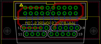
The second one (not pictured) is basically the same as the first, except the holes are exactly on a standard D-SUB pitch of 2.77mm. Then you can put 19 individual D-SUB crimp pins in the holes, solder them, and cut off the crimp part of each pin. It would be more awkward and expensive to assemble, but would give a better fit and might be more reliable in the long-term than bendy square header pins. I'm going to talk to the assembly guys I use and ask how much of a pain this would be to assemble.
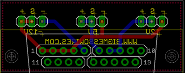
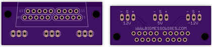
I also used the first footprint to make you a PCB for your power meter. This is basically the thing you asked me about over email that I said I wasn't going to do. It's got minus, sense, and plus broken out for each power rail. The lines are swapped for the -12V supply. You can send these Gerbers to Seeed or somebody if you want to get boards made.
power-meter-gerbers.zip
power-meter-eagle-files.zip
The first one uses the footprint I posted above, relying on slight bending in four sections of standard 0.1 inch header. Then it's got a standard IDC-20 header above that, where you can plug in a cable. The whole thing has to be very tiny in order to fit the recessed area around the I/O ports on the Mac 128K and 512K.
The second one (not pictured) is basically the same as the first, except the holes are exactly on a standard D-SUB pitch of 2.77mm. Then you can put 19 individual D-SUB crimp pins in the holes, solder them, and cut off the crimp part of each pin. It would be more awkward and expensive to assemble, but would give a better fit and might be more reliable in the long-term than bendy square header pins. I'm going to talk to the assembly guys I use and ask how much of a pain this would be to assemble.
I also used the first footprint to make you a PCB for your power meter. This is basically the thing you asked me about over email that I said I wasn't going to do.
It's got minus, sense, and plus broken out for each power rail. The lines are swapped for the -12V supply. You can send these Gerbers to Seeed or somebody if you want to get boards made.power-meter-gerbers.zip
power-meter-eagle-files.zip
is there supposed to be a gap in the middle?
gap in the middle of what?
your pin spacing for the DB19. I am looking at the pictures, and the pin spacing is wider in the middle?
Wow that is pretty cool steve your al right. I don't care what they say about you.
Yeah, that's intentional. The spacing in between the sets of 0.1" header is due to the difference in the grid spacings between the header and the DB-19 female port. The middle pin in each strip of 5 is dead-center on the D-SUB 2.77 mm grid, then its neighbors are slightly off. Then the pattern repeats in the next strip of 5, so there's a little gap. If all 9 or 10 pins in the same row of the PCB were evenly spaced, then header won't fit into the D-SUB port.
Steve you went to MIT?
Yeah, this was the school fight song:
secant! cosine! tangent! sine!
3.14159!
integral, radical mu d-v
slipstick, slide rule, MIT!
We didn't win a lot of football games.
secant! cosine! tangent! sine!
3.14159!
integral, radical mu d-v
slipstick, slide rule, MIT!
We didn't win a lot of football games.
I can tell...
MIT went 10-1 this year. That's one helluva fight song there.
Well I am not a sports fanatic, I dont watch it at all so i dunno. lol.
lol, I just wanted to feel like I knew something that you all didn't, which never happens around here. lol
steve is kind of a humble dude.
Let me know if you get that converter board made. I just submitted some identically-sized boards to OSHPark: $6 shipped for three copies. Hard to beat that!
ok maybe next weekend i will log into smart prototyping.com might get like 50 made up.
it sure is a beauty
it sure is a beauty
id like to make an half size version of your floppy emu, for hd 20 only.
i am going to experiment with Mike Mcmasters SCSI2SD and mod it to run from termination power. so it can be bus powered. pretty excited about that!!!!!!
i am going to experiment with Mike Mcmasters SCSI2SD and mod it to run from termination power. so it can be bus powered. pretty excited about that!!!!!!
Hey uni, with the mac plus you can add the termination diode in its little spot on the PCB too 
sweet man!! haha yeah because that is the only mac that doesn't supply term power.
Yup, and the PCB at least the versions I saw, has a spot for the diode but its un-populated. Once you populate a diode in there, boom you have termination power.
I wonder why termination power on the Plus would be deigned in, but left unimplemented like that?
c
c
Good question... Its also a 1985 board, so it could be a later version but they didnt populate the diode. I dont know why.
Mine came in today from Uni - time to give it a test drive. I know I could have made one cheaper, but its just nice to not have to do all the work sometimes!  Thanks man!
Thanks man!
yeah now you gotta get over to bmow and buy a Plus128k 512k rom kit
Because I can. lol
lol
I like!
oooo Now we are talking!!
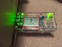
And actually, with a slight redesign on the floppy emulator, and using the internal ADC reference of the AVR and some resistor-dividers, technically the atmel can monitor voltage supply and report it to the LCD.
And actually, with a slight redesign on the floppy emulator, and using the internal ADC reference of the AVR and some resistor-dividers, technically the atmel can monitor voltage supply and report it to the LCD.
Mmm… glowy green electronics. [^]
I got back the boards for the two DB-19 substitutes, and put them together today. Both versions use pins sticking out of a PCB, and a couple of rectangular LEDs as mechanical guides. Then there's an IDC-20 connector on the other side of the PCB, where you can attach a cable.
Version A is based on a modification of Uniserver's idea, and uses 0.1" header split up into a few unevenly spaced sections. The DB-19 pin spacing is close to 0.1", but not exact, so the header pins end up getting kind of bent. That's not great, but this version is pretty cheap and easy to build.
Version B uses 19 individual D-SUB crimp pins. The spacing is perfect to match the DB-19 female port. But it's kind of a bitch to build this version, since you have to stuff 19 pins one at a time, and use a female port as a jig, and then cut off the crimp section of each pin when you're done. And the crimp pins are a lot more expensive than regular 0.1 inch male header.
Both versions seems to work just fine. I ran a Floppy Emu through some exercises on a couple of different Macs, with both versions of this board. There were no problems, and the connector stayed firmly in the socket.
I think I'm going to make another revision, that's a tweak of the version A shown here. But instead of splitting up the 0.1 inch header as 5-5 and 5-4, I'll split it as 3-4-3 and 3-3-3. That will be slightly more work to assemble, but will result in less pin bending.
Photos below, version A on right, version B on left:
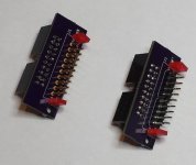
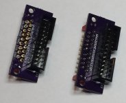
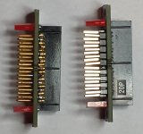
Version A is based on a modification of Uniserver's idea, and uses 0.1" header split up into a few unevenly spaced sections. The DB-19 pin spacing is close to 0.1", but not exact, so the header pins end up getting kind of bent. That's not great, but this version is pretty cheap and easy to build.
Version B uses 19 individual D-SUB crimp pins. The spacing is perfect to match the DB-19 female port. But it's kind of a bitch to build this version, since you have to stuff 19 pins one at a time, and use a female port as a jig, and then cut off the crimp section of each pin when you're done. And the crimp pins are a lot more expensive than regular 0.1 inch male header.
Both versions seems to work just fine. I ran a Floppy Emu through some exercises on a couple of different Macs, with both versions of this board. There were no problems, and the connector stayed firmly in the socket.
I think I'm going to make another revision, that's a tweak of the version A shown here. But instead of splitting up the 0.1 inch header as 5-5 and 5-4, I'll split it as 3-4-3 and 3-3-3. That will be slightly more work to assemble, but will result in less pin bending.
Photos below, version A on right, version B on left:
so i just got my single row headers from china. what if you just cut a bunch of individual pins of header, and just had them all properly spaced by the pcb? you need to make the LED's light. i'm sure it wouldn't be that hard.
Yeah, you could split them out as individual pins, with the DB-19 pin spacing instead of 0.1 inch spacing: 1-1-1-1-1-1-1-1-1. But individual pins are really easy to solder crookedly, and it's kind of a pain to fish out 19 pins one at a time. I was trying to strike a balance between ease of assembly and "pin bendiness".