
Thread
10bT in Duo Modem Slot - not my hack . . .
. . . but somehow this tidbit got the ball rolling!
Go team 68kMLA!!!!! :approve:
techknight & bbraun are running away with themselves on this one . . .eBay: USB to TTL Converter Module . . .
. . . looks like it might be fun try to to hook one up to the serial port of the Duo's Modem Bay Connector. }
PL2303HX USB to TTL Converter Module
Dunno what for . . . but I'm sure a use for something like this will come to me . . . even if it's not in a Duo!)
Go team 68kMLA!!!!! :approve:
Well I studied the powerbook duo modem connector, its a datapump connector hooked to the bus, and not a serial port, at least not that I had seen. In order to put a serial port thats usable on the modem connector, you would nee one of apples VIA chips i guess.
And that converter goes 1 direction, it gives USB computers a full RS232 serial port thats TTL compatible. For Arduinos and other crap. You could use one to plug a regular mac into your PC USB port for doing null modem file transfers, or if running XP, Basilisk localtalk access.
And that converter goes 1 direction, it gives USB computers a full RS232 serial port thats TTL compatible. For Arduinos and other crap. You could use one to plug a regular mac into your PC USB port for doing null modem file transfers, or if running XP, Basilisk localtalk access.
Well, I am not entirely sure of the data pump interface on the Duo modem, but you might even be able to get away with just a simple VIA/SCC or just SCC itself attached to the header connector. But I dont have the spec sheet of the 144 data pump IC.
But in theory since its a direct backbone connection to the databus, you could even make a custom made WiFi card or ethernet card to go into this slot, which would require an entirely custom driver to make use of the data pump mechanism, but it would work in theory.
There are a crapload of realtek chipsets, and other chipsets out there that have a vast amount of public support on in the embedded market, could even use one of these and use a C library thats already out there, to be embedded inside a codewarrior project. Right up bbrauns alley. I could do the hardware, but i dont know codewarrior or low-levels of the system software, so i would need him to write an ethernet driver using public libraries. lol.
The only pitfall I see is I dont know how fast the modem datapump backbone is. just one of those things if you can get at least a 1megabit throughput, itll be decent.
But in theory since its a direct backbone connection to the databus, you could even make a custom made WiFi card or ethernet card to go into this slot, which would require an entirely custom driver to make use of the data pump mechanism, but it would work in theory.
There are a crapload of realtek chipsets, and other chipsets out there that have a vast amount of public support on in the embedded market, could even use one of these and use a C library thats already out there, to be embedded inside a codewarrior project. Right up bbrauns alley. I could do the hardware, but i dont know codewarrior or low-levels of the system software, so i would need him to write an ethernet driver using public libraries. lol.
The only pitfall I see is I dont know how fast the modem datapump backbone is. just one of those things if you can get at least a 1megabit throughput, itll be decent.
Actually i finally found the datasheet to the data pump IC here:
http://www.datasheetarchive.com/dl/Datasheets-8/DSA-153646.pdf
Believe it or not, the datapump actually extends a serial interface via the V.21 interface. So technically, you could use the datapump itself as a serial port. Of course, limited to 14.4 (yuck).
But the datapump does use a 5-bit addressing scheme, and 8 databits plus a chipselect, R/W control lines, and an IRQ signal to the host microprocessor (which is probably the VIA).
This is nice, becuase we could put anything in there, within the means of the 8-bit data bus. So technically they do make and support 8-bit based ethernet controllers, so thats easy. But still need a driver and figure out where the "modem" is mapped in the duo addressing system.
http://www.datasheetarchive.com/dl/Datasheets-8/DSA-153646.pdf
Believe it or not, the datapump actually extends a serial interface via the V.21 interface. So technically, you could use the datapump itself as a serial port. Of course, limited to 14.4 (yuck).
But the datapump does use a 5-bit addressing scheme, and 8 databits plus a chipselect, R/W control lines, and an IRQ signal to the host microprocessor (which is probably the VIA).
This is nice, becuase we could put anything in there, within the means of the 8-bit data bus. So technically they do make and support 8-bit based ethernet controllers, so thats easy. But still need a driver and figure out where the "modem" is mapped in the duo addressing system.
too ugly. Id rather just plug a card into the modem connector on the duo, and call it done, all in one integrated solution with no messy wires running every which way, and it gives me a nice RJ45 jack on the back where the modem RJ11 once was. I've got a weird way of doing things, "different".
Anyway.. I need to find out where the address space is for the duo modem card. There is a data pump driver in ROM supposidly, which will have to be hooked to disable it. But at the same time, i need to find its location, as obviously this will reveal the address space.
Edit: Then again, i could emulate the data pump and the driver/software would establish a false PPP to it, but its reality an ethernet connection. But that limits its uses a bit, like not being able to use ethertalk appleshare, etc....
probably going to be easier to disable the data pump driver with a system extension that contains the proper ethernet driver.
As far as the DeclROM thing, i have limited knowledge in the area, and I dont have that particular book. So thats out the window.
Anyway.. I need to find out where the address space is for the duo modem card. There is a data pump driver in ROM supposidly, which will have to be hooked to disable it. But at the same time, i need to find its location, as obviously this will reveal the address space.
Edit: Then again, i could emulate the data pump and the driver/software would establish a false PPP to it, but its reality an ethernet connection. But that limits its uses a bit, like not being able to use ethertalk appleshare, etc....
probably going to be easier to disable the data pump driver with a system extension that contains the proper ethernet driver.
As far as the DeclROM thing, i have limited knowledge in the area, and I dont have that particular book. So thats out the window.
I picked one of these things up because, well, for <$3 who doesn't need USB to TTL serial?
I was reading over the Duo System dev notes, and I couldn't really find information on where the data pump is mapped into the address space. It looks like disassembly of the datapump driver might be the most expedient way of getting the address mapping...
JFYI, for disassembly, I've been using the fdisasm tool from minivmac. It allows distribution of annotations separate from the ROM to allow collaboration without distributing the copyrighted material, which I kind of like. It took a little bit to setup the minivmac instance and learn the meanings of the various files it uses and their syntax, but once I got the hang of it, things have been going well. If you're interested, I can probably setup the annotations for the driver's entry points.
I've been using it for a different project on the IIsi ROM.
FWIW, you don't NEED declroms... If you're going to occupy a nubus slot or pseudo-slot address space, you probably should. Outside of that, your declrom probably won't be probed anyway. If you're fine with hardware just sitting there not doing anything unless you have the proper software installed, you just need a non-conflicting address space to occupy AFAIK. You could probably even use the RAM expansion port and have a device occupy the top end of the RAM expansion address space (leaving a dead zone between the top of whatever RAM you do have and your device to help foil detection).
I was reading over the Duo System dev notes, and I couldn't really find information on where the data pump is mapped into the address space. It looks like disassembly of the datapump driver might be the most expedient way of getting the address mapping...
JFYI, for disassembly, I've been using the fdisasm tool from minivmac. It allows distribution of annotations separate from the ROM to allow collaboration without distributing the copyrighted material, which I kind of like. It took a little bit to setup the minivmac instance and learn the meanings of the various files it uses and their syntax, but once I got the hang of it, things have been going well. If you're interested, I can probably setup the annotations for the driver's entry points.
I've been using it for a different project on the IIsi ROM.
FWIW, you don't NEED declroms... If you're going to occupy a nubus slot or pseudo-slot address space, you probably should. Outside of that, your declrom probably won't be probed anyway. If you're fine with hardware just sitting there not doing anything unless you have the proper software installed, you just need a non-conflicting address space to occupy AFAIK. You could probably even use the RAM expansion port and have a device occupy the top end of the RAM expansion address space (leaving a dead zone between the top of whatever RAM you do have and your device to help foil detection).
hey bbraun, any info you can legally give on trying to isolate the driver out of the ROM would help me out.
I am serious, I want to make a NIC that fits where the modem used to go, utilizing the original bus if possible.
I will have to fire up my duo and dump the ROM image so I can analyze it.
Using the RAM slot isnt a bad idea, considering if I make a new modem card NIC, i would have to map it out exactly as it contains both the power/standby button as well. But thats no big deal in Eagle or pulsonix or some other CAD package. The footprint of the edge connector might be a bit difficult to reconstruct though.
I am serious, I want to make a NIC that fits where the modem used to go, utilizing the original bus if possible.
I will have to fire up my duo and dump the ROM image so I can analyze it.
Using the RAM slot isnt a bad idea, considering if I make a new modem card NIC, i would have to map it out exactly as it contains both the power/standby button as well. But thats no big deal in Eagle or pulsonix or some other CAD package. The footprint of the edge connector might be a bit difficult to reconstruct though.
The Modem slot though, has 5 bit addressing with an 8 bit bi-directional data bus, including a Read/Write line, plus an IRQ line. It also has a Chip Select line, so that tells me its bus has to be mapped through one of the VIAs, or System I/O controller.
Should be sufficient for a basic NIC, but if i wanted to integrate, say, an SD card reader or something other, it might slow things down, unless i hooked into the RAM address slots, which give me direct processor access.
Should be sufficient for a basic NIC, but if i wanted to integrate, say, an SD card reader or something other, it might slow things down, unless i hooked into the RAM address slots, which give me direct processor access.
As far as the ethernet controller, I have been looking at these:
http://www.eetasia.com/ART_8800434318_1034362_NP_6dc505a4.HTM
PIC has a new 8-bit microcontroller that has a PHY and MAC Ethernet interface built-in. With this being a fully flash-able, programmable microcontroller, we can make this thing do whatever we want to lessen the load off of the Duo itself. It has a built in packet buffer, etc.... and they have a free TCP/IP stack code already made for this MCU family, so MacTCP wouldnt even be needed. lol. it could be handled entirely in the PIC's hardware, and just have an apple driver handle the hardware-based TCP/IP stack.
Possibilities are endless. Plus its bootloader supported so i can flash the PIC to whatever when its in-system via the bus.
Hell, you could even write a net-boot application and putting the image/location information inside the RAM of the PIC, so when the machine reboots it could in theory fetch a boot image from a server and boot the mac, albeit probably slow. Plus a modified ROM would be needed.
http://www.eetasia.com/ART_8800434318_1034362_NP_6dc505a4.HTM
PIC has a new 8-bit microcontroller that has a PHY and MAC Ethernet interface built-in. With this being a fully flash-able, programmable microcontroller, we can make this thing do whatever we want to lessen the load off of the Duo itself. It has a built in packet buffer, etc.... and they have a free TCP/IP stack code already made for this MCU family, so MacTCP wouldnt even be needed. lol. it could be handled entirely in the PIC's hardware, and just have an apple driver handle the hardware-based TCP/IP stack.
Possibilities are endless. Plus its bootloader supported so i can flash the PIC to whatever when its in-system via the bus.
Hell, you could even write a net-boot application and putting the image/location information inside the RAM of the PIC, so when the machine reboots it could in theory fetch a boot image from a server and boot the mac, albeit probably slow. Plus a modified ROM would be needed.
Weird, I took a look at the ROM on my 270c. Usually drivers are DRVR resources in the main ROM. The 270c has the following drivers:
.Backlight, .Sound, .Sony, .MPP, .ATP, XPP, .netBOOT, .ATBOOT, .EDisk, .BCScreen, .ENET
I don't recognize .BCScreen, but everything else seems pretty normal, I'm not seeing an obvious driver for the data pump. Perhaps it's not really a driver in the normal DRVR sense, but a set of routines somewhere following a different layout convention? Or gets loaded through an onboard declrom somewhere.
Also, .AIn, .AOut, .BIn, .Bout are the normal serial & printer port drivers, but I don't see them in ROM either.
FWIW, I'm using ROMmie, which is a pretty nice tool for extraction, it includes both a dump of the ROM and parses out the resource data into a .rsrc file suitable for use with Resedit or Resorcerer or similar.
.Backlight, .Sound, .Sony, .MPP, .ATP, XPP, .netBOOT, .ATBOOT, .EDisk, .BCScreen, .ENET
I don't recognize .BCScreen, but everything else seems pretty normal, I'm not seeing an obvious driver for the data pump. Perhaps it's not really a driver in the normal DRVR sense, but a set of routines somewhere following a different layout convention? Or gets loaded through an onboard declrom somewhere.
Also, .AIn, .AOut, .BIn, .Bout are the normal serial & printer port drivers, but I don't see them in ROM either.
FWIW, I'm using ROMmie, which is a pretty nice tool for extraction, it includes both a dump of the ROM and parses out the resource data into a .rsrc file suitable for use with Resedit or Resorcerer or similar.
Well, thats odd. the developer note said it had a Data Pump Driver in the ROM. hmmm..... it didnt say anything about a DeclROM either.
it also says in the developer note, there is an extension and a control panel for the express modems in the Duo. Maybe thats it? And it all goes through the communication toolbox.
it also says in the developer note, there is an extension and a control panel for the express modems in the Duo. Maybe thats it? And it all goes through the communication toolbox.
After boot (which includes any System/INIT loaded drivers...) I have the following drivers installed:
.Sony, .Sound, .Sony, .AIn, .AOut, .BIn, .BOut, .MPP, .ATP, .ASYC00, .XPP, .netBOOT, .XPP, .EDisk, .AppleSoundInput, .SLM, .DSP, .ipp, .CTBIn, .CTBOut
.ASYC00, .SLM, .DSP and the .CTB* drivers are possibilities. Presumably .CTBIn/Out is communications toolbox...
The loaded driver's device control entry should indicate whether a given driver exists in ROM or RAM, but my driver inspection tool isn't sophisticated enough to decode that yet.
.Sony, .Sound, .Sony, .AIn, .AOut, .BIn, .BOut, .MPP, .ATP, .ASYC00, .XPP, .netBOOT, .XPP, .EDisk, .AppleSoundInput, .SLM, .DSP, .ipp, .CTBIn, .CTBOut
.ASYC00, .SLM, .DSP and the .CTB* drivers are possibilities. Presumably .CTBIn/Out is communications toolbox...
The loaded driver's device control entry should indicate whether a given driver exists in ROM or RAM, but my driver inspection tool isn't sophisticated enough to decode that yet.
.DSP is it. Rockwell refers to the Data Pump as the DSP alot.
I read carefully the document, first line of the Data Pump says, "The Data Pump driver is at the lowest end of the modem software..."
So its an INIT or DRVR in the software....
Also, the CTB is the communications toolbox that communicates with the driver to the internal modem. the CTB has a custom serial driver, so un-aware serial modem apps can treat the internal modem as if it were a serial port through emulation in the CTB.
I read carefully the document, first line of the Data Pump says, "The Data Pump driver is at the lowest end of the modem software..."
So its an INIT or DRVR in the software....
Also, the CTB is the communications toolbox that communicates with the driver to the internal modem. the CTB has a custom serial driver, so un-aware serial modem apps can treat the internal modem as if it were a serial port through emulation in the CTB.
The .DSP driver comes from the System file on my 7.1 machine.
Here's the process I went through to create the basic annotations, and it's probably a good idea to follow along exactly since the end file's offsets important. It's an exercise left to the reader to get a minivmac instance up enough to run the basic tools below. Mine is running 7.0.1 FWIW.
You can probably also get by without minivmac, and just run the fdisasm tools locally on the duo. I just used minivmac for convenience, since I tend to spend a lot of time making multiple iterations of the annotations & disassembly, and it's just easier and faster on a modern machine with minivmac.
* From 7.1, I duplicated my System file because if you open the live System, Resedit complains.
* Opened the duplicate in Resedit.
* In the DRVR resources, copied (cmd-c/Edit->Copy) the .DSP resource. My version has a size of 17082.
* Created a new file in Resedit called "DSP.rsrc" (file name gets encoded in the file, so using the same name is probably a good idea). And paste the copied DSP DRVR into it.
* Used Compact Pro's hqx encoding for safe transport to a modern machine that runs minivmac. This particular encoding probably isn't necessary, anything that you can use to copy the file into minivmac while preserving the resource fork is probably fine.
* Once inside a working minivmac instance (I used ImportFl to get the DSP.rsrc.hqx file into minivmac), remove the binhex encoding or whatever other wrapper format you used.
* Attach this disk to minivmac. You should see bin_names, bin_map, format, and the fdisasm utilities I'm about to mention. The fdisasm utilities are all GPL with source and licenses obtainable from the following links.
* Place the DSP.rsrc file on the mounted duodsp disk.
* Run GetRsFrk to dump the resource fork into the data fork, so it'll be included in the disassembly. It'll generate a "bin" file in the same directory. This is the file used by all the fdisasm related tools.
* Run fdisasm. It will generate a listing file. That's the disassembled text. I usually export it from minivmac using ExportFl, since it's usually easier to just view text on the host system.
Hopefully, after all that, you'll have the disassembled file. The driver its self started at offset 0x104 for me, and starts with the word 0x4440. I've named the driver's open/prime/control/status/close entry points (defined in bin_names) and commented where the DRVR resource header starts (defined in the format file). You can add your own comments to the format file, and name labels, procedures, etc. in the bin_names, then rerun fdisasm to generate a new listing with the new comments/names inline.
Here's the process I went through to create the basic annotations, and it's probably a good idea to follow along exactly since the end file's offsets important. It's an exercise left to the reader to get a minivmac instance up enough to run the basic tools below. Mine is running 7.0.1 FWIW.
You can probably also get by without minivmac, and just run the fdisasm tools locally on the duo. I just used minivmac for convenience, since I tend to spend a lot of time making multiple iterations of the annotations & disassembly, and it's just easier and faster on a modern machine with minivmac.
* From 7.1, I duplicated my System file because if you open the live System, Resedit complains.
* Opened the duplicate in Resedit.
* In the DRVR resources, copied (cmd-c/Edit->Copy) the .DSP resource. My version has a size of 17082.
* Created a new file in Resedit called "DSP.rsrc" (file name gets encoded in the file, so using the same name is probably a good idea). And paste the copied DSP DRVR into it.
* Used Compact Pro's hqx encoding for safe transport to a modern machine that runs minivmac. This particular encoding probably isn't necessary, anything that you can use to copy the file into minivmac while preserving the resource fork is probably fine.
* Once inside a working minivmac instance (I used ImportFl to get the DSP.rsrc.hqx file into minivmac), remove the binhex encoding or whatever other wrapper format you used.
* Attach this disk to minivmac. You should see bin_names, bin_map, format, and the fdisasm utilities I'm about to mention. The fdisasm utilities are all GPL with source and licenses obtainable from the following links.
* Place the DSP.rsrc file on the mounted duodsp disk.
* Run GetRsFrk to dump the resource fork into the data fork, so it'll be included in the disassembly. It'll generate a "bin" file in the same directory. This is the file used by all the fdisasm related tools.
* Run fdisasm. It will generate a listing file. That's the disassembled text. I usually export it from minivmac using ExportFl, since it's usually easier to just view text on the host system.
Hopefully, after all that, you'll have the disassembled file. The driver its self started at offset 0x104 for me, and starts with the word 0x4440. I've named the driver's open/prime/control/status/close entry points (defined in bin_names) and commented where the DRVR resource header starts (defined in the format file). You can add your own comments to the format file, and name labels, procedures, etc. in the bin_names, then rerun fdisasm to generate a new listing with the new comments/names inline.
Yup. I will do that tomorrow after I get done working on someones virus-ridden PC.
Should be interesting what I find. Hopefully the driver will have all the necessary functions needed to control the modem bus. Then I can develop some simple hardware based off the PIC ethernet controller, and maybe make something work. ASSUMING the DSP is the driver.
I guess one way to find out is run MacsBug and do a modem query or something, itll eventually hop through the driver... I really dont know why I want to go through all this trouble and make a modem slot ethernet adapter, but I like not having wires strung every which way, more in favor of a plug-in solution Besides, I found a couple prototype 2layer PCB production services that are cheap for 5 boards minimum.
Maybe I should make some hardware after ironing out the ability to take control of the modem bus, and produce some test boards. Send one to ya if you want to play with it.
Should be interesting what I find. Hopefully the driver will have all the necessary functions needed to control the modem bus.
Then I can develop some simple hardware based off the PIC ethernet controller, and maybe make something work. ASSUMING the DSP is the driver.I guess one way to find out is run MacsBug and do a modem query or something, itll eventually hop through the driver... I really dont know why I want to go through all this trouble and make a modem slot ethernet adapter, but I like not having wires strung every which way, more in favor of a plug-in solution
Besides, I found a couple prototype 2layer PCB production services that are cheap for 5 boards minimum.Maybe I should make some hardware after ironing out the ability to take control of the modem bus, and produce some test boards. Send one to ya if you want to play with it.
Well handing over a disk image isnt going to make me learn anything. lol. I need to learn the lower-level stuff for a reason. If i make hardware that works with macintosh, How do i ever expect to make it work in software besides using peek/poke routines in higher level languages that isolate themselves from the low-level system like the toolbox? (such as RealBasic which I am familiar with)
NoPro guys . . . I just toss'em out there and see what happens . . .
. . . it's not usually what I expected to be possible, but it's almost always interesting! :approve:
This stuff is waaaayyyyyyy over my pay grade. I was just gonna toss a hacked Micro-ENSC into the HDD Bay of the 2300c, connected to the internal SCSI Connector/Cable, alongside an IDE Hard Disk replacement of some kind. Then I'd stick an RJ-45 onto the Power Board where the Modem's RJ-11 lives and connect it with a wire run to the NIC in the HDD Bay!
Ethernet in the Modem Bay on a custom PCB is a way cooler hack!
This is what I get for procrastinating for ten years on a hack . . .
. . . I get trampled by eager young whipper snappers doing it with technology so advanced as to be indistinguishable from Magic! :I
Go for it guys, just let me know what to re-name my thread!)
. . . it's not usually what I expected to be possible, but it's almost always interesting! :approve:
This stuff is waaaayyyyyyy over my pay grade. I was just gonna toss a hacked Micro-ENSC into the HDD Bay of the 2300c, connected to the internal SCSI Connector/Cable, alongside an IDE Hard Disk replacement of some kind. Then I'd stick an RJ-45 onto the Power Board where the Modem's RJ-11 lives and connect it with a wire run to the NIC in the HDD Bay!
Ethernet in the Modem Bay on a custom PCB is a way cooler hack!
This is what I get for procrastinating for ten years on a hack . . .
. . . I get trampled by eager young whipper snappers doing it with technology so advanced as to be indistinguishable from Magic! :I
Go for it guys, just let me know what to re-name my thread!
) Well, heres the thing. The Micro-ENSC idea is great, and the easiest approach without getting deep into the system hardware and software configurations.
The problem: Where to get this adapter. and are they being made? could they be made again? I doubt it, and i doubt it.
But FWIW, if this modem slot idea works out, I am going to keep everything open source. open hardware, open software, etc... so anyone can make them. if there is a need for one, make it
if bbraun makes a driver, or teaches me how to make one, im sure he would keep the codewarrior project open source as well too. (i hope)
The problem: Where to get this adapter. and are they being made? could they be made again? I doubt it, and i doubt it.
But FWIW, if this modem slot idea works out, I am going to keep everything open source. open hardware, open software, etc... so anyone can make them. if there is a need for one, make it
if bbraun makes a driver, or teaches me how to make one, im sure he would keep the codewarrior project open source as well too. (i hope)
That's me . . . the KnuckleDraggin'HardwareHacker type! Take chunks of off the shelf hardware . . .
lop off some bits here, move some other bits there . . . flip the rest of the bits upside down or sideways . . . }
. . . so's they'll fit in somewhere and work in a Mac that nobody thought they belonged inside, much less fit!)
I get a kick out of watching you kids take a more elegant approach . . . than Junkyard Wars! [ ] ]'>
lop off some bits here, move some other bits there . . . flip the rest of the bits upside down or sideways . . . }
. . . so's they'll fit in somewhere and work in a Mac that nobody thought they belonged inside, much less fit!
) I get a kick out of watching you kids take a more elegant approach . . . than Junkyard Wars! [
] ]'>Yea. LOL I did the junkyard approach to the old IBM 600e and 600x series thinkpads. stuck NiMH AA batteries and holders inside the compartment where the Li-Ion originally went. soldered it directly to the system board, and ductaped the bottom hole that held the batteries in place. LOL it worked believe it or not....
The CTBIn/CTBOut drivers come from the PowerBook Setup control panel on 7.1, presumably purely for that Modem: Compatible/Normal radio button!
Anyway, mostly the same as above:
* Open PowerBook Setup in Resedit, copy the CTBIn & CTBOut resources
* Paste them into a new file named CTB.rsrc
* Follow the same steps for transferring the CTB.rsrc file to minivmac, preserving the resource fork
* Grab this disk image, the same as before, except there are CTB and DSP folders differentiating the two.
* Inside the CTB folder, run GetRsFrk as before, which will generate the "bin" file.
* Run the FDisasm tool to generate the listing
For me, the CTBIn driver header started at $104 again (a good sign this is repeatable!) starting with the word 4d 00, with the Open function starting at $168.
I've labeled the open/prime/control/status/close functions of the In and Out drivers again. It looks like they do some jumping around and the FindCode tool wasn't able to follow all the jumping. If you think there's more code at a specific address, launch the FindCode tool, type in the hex offset you want it to start disassembling at, then hit cmd-g/FIle->Go and it'll update bin_map and bin_names, and run FDisasm again for you, updating the listing file.
For example, this seems to use PEA.L , then branches, does some other stuff, pops the address off the stack, and JSR's to it. FindCode couldn't follow that with all the gunk in between, so you'll need to tell FindCode to disassemble at that offset (if it really is pushing the address of code onto the stack, sometimes that's pushing the address of constant data and if you disassemble that you'll get garbage).
Anyway, mostly the same as above:
* Open PowerBook Setup in Resedit, copy the CTBIn & CTBOut resources
* Paste them into a new file named CTB.rsrc
* Follow the same steps for transferring the CTB.rsrc file to minivmac, preserving the resource fork
* Grab this disk image, the same as before, except there are CTB and DSP folders differentiating the two.
* Inside the CTB folder, run GetRsFrk as before, which will generate the "bin" file.
* Run the FDisasm tool to generate the listing
For me, the CTBIn driver header started at $104 again (a good sign this is repeatable!) starting with the word 4d 00, with the Open function starting at $168.
I've labeled the open/prime/control/status/close functions of the In and Out drivers again. It looks like they do some jumping around and the FindCode tool wasn't able to follow all the jumping. If you think there's more code at a specific address, launch the FindCode tool, type in the hex offset you want it to start disassembling at, then hit cmd-g/FIle->Go and it'll update bin_map and bin_names, and run FDisasm again for you, updating the listing file.
For example, this seems to use PEA.L , then branches, does some other stuff, pops the address off the stack, and JSR's to it. FindCode couldn't follow that with all the gunk in between, so you'll need to tell FindCode to disassemble at that offset (if it really is pushing the address of code onto the stack, sometimes that's pushing the address of constant data and if you disassemble that you'll get garbage).
Ive seen worse when disassembling and trying to use the ST version of the 68HC05 and 68HC11 with IDApro as they added a 16 bit extended opcode system on top of the original 68HC05 compatible 8 bit system, using indirect jumps, etc.... nuts. So i know exactly how that is. I just am not familiar with 68k YET.... but i will be. cant be much different than the older 68HC series.
BTW, do you know if the CTB driver took any branches/called into another driver resource? or was it contained within itself. Anyway, I am off to bed, and ill start crunching this code tomorrow when i get finished with this stupid PC over here.
BTW, do you know if the CTB driver took any branches/called into another driver resource? or was it contained within itself. Anyway, I am off to bed, and ill start crunching this code tomorrow when i get finished with this stupid PC over here.
I haven't done much disassembling of these beyond the initial entry points, it was mostly intended as a starting point for you to take a look. However, DRVRs shouldn't be branching directly to stuff outside themselves. They'll use A-Traps and reference low memory globals, but that's more or less it. The A-Traps here will typically show up as an undisassembled data constant, although if you include the trap_names file from one of the ROM disassemblies on the FDisasm site, FDisasm will correctly display what A-Trap is being called. Including the abs_names file will do the same thing for low memory globals.
The caveat to calling out to another resource is a driver can load another resource using GetResource or similar (it'll show up as an A-Trap, if you include that file), then once loaded, start executing it. The .netBOOT driver does this, it loads the .ATBOOT DRVR resource, installs the driver, then opens it.
However, DRVRs shouldn't be branching directly to stuff outside themselves. They'll use A-Traps and reference low memory globals, but that's more or less it. The A-Traps here will typically show up as an undisassembled data constant, although if you include the trap_names file from one of the ROM disassemblies on the FDisasm site, FDisasm will correctly display what A-Trap is being called. Including the abs_names file will do the same thing for low memory globals.The caveat to calling out to another resource is a driver can load another resource using GetResource or similar (it'll show up as an A-Trap, if you include that file), then once loaded, start executing it. The .netBOOT driver does this, it loads the .ATBOOT DRVR resource, installs the driver, then opens it.
ugh. this is a pain. lol. I am trying to get all my mac emu files transferred over from my main machine, to a junk laptop that is modern enough to be an intermediate machine. Why? because i need a floppy disk to transfer files between my duo and my main machine as I have no floppy drive.
I dont have a null modem cable made either, so I have to use floppy to transfer between machines, with an in-between machine thats networked to my main machine. Since the in-between machine runs windows 98, and my main machine runs windows 7, they dont "talk" to each other, so I have to use FTP to transfer between the two.
fun... but ill get there.
I dont have a null modem cable made either, so I have to use floppy to transfer between machines, with an in-between machine thats networked to my main machine. Since the in-between machine runs windows 98, and my main machine runs windows 7, they dont "talk" to each other, so I have to use FTP to transfer between the two.
fun... but ill get there.
:lol: Been there, done that!
SCSI & USB ZIP Drives & Disk(s) are the answer to all your EtherNet/SneakerNet trials and tribulations.
I can lend you all three for this project, or I can loan you a SCSI <-> EtherNet Box to make your life easier for this project . . . unless you have some interesting trade goods! [] ]'>
SCSI & USB ZIP Drives & Disk(s) are the answer to all your EtherNet/SneakerNet trials and tribulations.
I can lend you all three for this project, or I can loan you a SCSI <-> EtherNet Box to make your life easier for this project . . . unless you have some interesting trade goods! [
] ]'>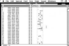
I don't think it'll get very far in easy68k, but you could write an app that'll open the driver, then trace through it using macsbug... But that will only get you through the open routine. The Control and Status routines each key off the csCode element of the ParamBlock structure, a pointer to which gets passed in A0 (DCtlEntry structure pointer is in A1, return value in D0), so you pretty much either need to disassemble those routines to figure out what values get passed in and what they mean, or set a macsbug breakpoint on those routines and fiddle around with stuff until they get called, then follow them through.
Ya, its totally broken in easy68k becuase it doesnt understand the PCrel function that the disassembler used. And it complained about the addressing modes. I am assuming everything in a driver is going to be a relative addressing mode, because it doesnt know what the OS is doing and where the OS places it in memory. You would think anyway...
Ill try the macsbug thing, ill probably use a terminal program and try to talk to the modem. This way, i can see what address the modem resides.
Ill try the macsbug thing, ill probably use a terminal program and try to talk to the modem. This way, i can see what address the modem resides.
Not a chance, RUN WITH IT!!!!!!!!!!! [] ]'> Go team 68kMLA!!!!!!!!!!!!! :approve:
Dinosaurs get pissed off at themselves for becoming Dinosaurs! [ ] ]'>
BTW: check the last post of the first page, I requested a suitable title and offered to change it to anything you suggested. This stuff if fabulous!
I'm just embarrassed that I can't follow even 10% of a great discussion/learning experience/hacking project . . . :-/
edit: Right on the money! I am VERY impressed!
] ]'> Go team 68kMLA!!!!!!!!!!!!! :approve: Dinosaurs get pissed off at themselves for becoming Dinosaurs! [
] ]'>BTW: check the last post of the first page, I requested a suitable title and offered to change it to anything you suggested. This stuff if fabulous!
I'm just embarrassed that I can't follow even 10% of a great discussion/learning experience/hacking project . . . :-/
edit: Right on the money! I am VERY impressed!
Hey, don't feel too bad. I'm right there with you barely following this. I've always wanted to be that level of hacker but couldn't. So I'll sit on the sidelines and cheer y'all on. I'm with Trash80toHP_Mini, keep goin with this. It's projects like this that keep our old machines alive and still productive.
PS: Great example would be the NADSBox at club100
PS: Great example would be the NADSBox at club100
FWIW, I've added mappings for a near full disassembly of the CTP drivers, and a mostly complete disassembly of the DSP driver.
duodsp4.dsk
Nothing popped out at me while disassembling, but I haven't followed it closely. I mostly just set up the mappings.
From the Duo System devnote, it's probably somewhere in the $5000 0000 - $5FFF FFFF range, since that's dedicated to IO devices.
duodsp4.dsk
Nothing popped out at me while disassembling, but I haven't followed it closely. I mostly just set up the mappings.
From the Duo System devnote, it's probably somewhere in the $5000 0000 - $5FFF FFFF range, since that's dedicated to IO devices.
Well i could take the brute-force method out, wiring the modem slot address/data lines to buffers and then to LEDs.
Then using a small BASIC app i could rotate through the addresses until I hit the one that lights the LEDs. Bad thing about this, is if there is a configuration register or data direction register somewhere that has to be set before this bus will operate, but i doubt it.
Then using a small BASIC app i could rotate through the addresses until I hit the one that lights the LEDs. Bad thing about this, is if there is a configuration register or data direction register somewhere that has to be set before this bus will operate, but i doubt it.
I might have to pull out my 68K duo instead of my PPC duo running OS8. And put a fresh load of system 7 on my 68k duo, and try it again. On a hardware note, I wonder if i will trip any system errors or GPFs if i "scan the band" if you know what mean, until i find the one that controls the modem.
I've been (and will probably continue to be for a week or so) distracted, but...
It sounds like your file doesn't match my file. You'll probably need to get the DRVRs from 7.1, like what I've got.
But... Are you sure the data pump is wired into the address space at all? The PowerBook Duo System devnote includes a pinout of the modem connector, and it is pretty modem specific. No address or data lines in the description.
It sounds like your file doesn't match my file. You'll probably need to get the DRVRs from 7.1, like what I've got.
But... Are you sure the data pump is wired into the address space at all? The PowerBook Duo System devnote includes a pinout of the modem connector, and it is pretty modem specific. No address or data lines in the description.
No, becuase they are not listed in the Devnote. Why they didnt list them, I have no idea. There isnt even a hint of a serial port either. Just control lines they list. I guess it wasnt intended for 3rd party manufacturers to produce modems.
However If you pull the datasheet to the RCV144DPL, you will notice that the IC requires a Data and Address control bus. The IC does also give you a full RS232 serial port, but its Synchronous (USRT) so it requires a clock signal for the Send and Receive control lines, its for the V.24 compressor. But its all done in software/CPU i think on the duo. Plus, why would they have 50 pins on the connector? almost all of them are used it appears.
However If you pull the datasheet to the RCV144DPL, you will notice that the IC requires a Data and Address control bus. The IC does also give you a full RS232 serial port, but its Synchronous (USRT) so it requires a clock signal for the Send and Receive control lines, its for the V.24 compressor. But its all done in software/CPU i think on the duo. Plus, why would they have 50 pins on the connector? almost all of them are used it appears.
Is this the place I drop the fact/factoid/rumor that the Mac serial ports can take an external clock signal, and run faster than Localtalk? I know the Farallon serial/ethernet adapters do it.
Also, the second hardware serial port is available from the docking connector, yeah?
And:
http://www.sparkfun.com/products/10004
http://www.sparkfun.com/products/10253
http://www.sparkfun.com/products/10269
http://www.sparkfun.com/products/10808
http://www.sparkfun.com/products/10822 (versions available with on-PCB antenna or antenna socket)
http://www.sparkfun.com/products/11049 (bare module version of above)
Seems to me the cleanest thing from a Mac point of view would be something that pretends to be a modem, and squirts Ethernet/WiFi packets out the other end (which, from my reading, some of the above do).
But Trash - you have gotta get it clear in your head that just because something says USB doesn't mean it converts both ways!
Also, the second hardware serial port is available from the docking connector, yeah?
And:
http://www.sparkfun.com/products/10004
http://www.sparkfun.com/products/10253
http://www.sparkfun.com/products/10269
http://www.sparkfun.com/products/10808
http://www.sparkfun.com/products/10822 (versions available with on-PCB antenna or antenna socket)
http://www.sparkfun.com/products/11049 (bare module version of above)
Seems to me the cleanest thing from a Mac point of view would be something that pretends to be a modem, and squirts Ethernet/WiFi packets out the other end (which, from my reading, some of the above do).
Agreed
But Trash - you have gotta get it clear in your head that just because something says USB doesn't mean it converts both ways! Ive looked at all those modules, and As i said the ethernet hardware is not set in stone yet. I just wanted to figure out the communication bus. I have used some of those modules, like the bluetooth module is an RS232 over BT, good for mobile phone or tablet devices that you need an RS232 port for. Wireless at that.
I dont have any experience in the WiFly modules, but the serial controlled wireless radios would be ok. I would have to have the one that you can program the application, because having the TCP/IP stack is great, but you still need ethertalk stack. If it isnt supported, you would have to do appletalk over TCP/IP.
Again, MY goal is not to have any "extra" wires run anywhere. And not have a hump on the back of the duo. (for me at least). Trust me, I can think of 10000 ways to wire up hardware, mostly go to the PDS bus. I could have a dongle in the back either in the PDS slot, or in the serial port asking to get snapped off.
Or... i can have a wireless/wired card in the modem slot and be done
I dont have any experience in the WiFly modules, but the serial controlled wireless radios would be ok. I would have to have the one that you can program the application, because having the TCP/IP stack is great, but you still need ethertalk stack. If it isnt supported, you would have to do appletalk over TCP/IP.
Again, MY goal is not to have any "extra" wires run anywhere. And not have a hump on the back of the duo. (for me at least). Trust me, I can think of 10000 ways to wire up hardware, mostly go to the PDS bus. I could have a dongle in the back either in the PDS slot, or in the serial port asking to get snapped off.
Or... i can have a wireless/wired card in the modem slot and be done
Actually, you just need to do a PCB for underneath the Duo Mobo, a Flex circuit would be even better, but I don't know about short run/prototyping costs for flex circuits.
Pull the entire PDS into the HDD Bay. That'll give you 16 bits for the T-REX ASIC enabled 1400 PCMCIA Card Cage and its IR-Talk sub-system. This was slated for the announced, but never realized/rleased, PCMCIA UltraDock. The Hard-Tooling Costs for the PCMCIA UltraDock's Plastics were somewhat recouped by the pitiful (relatively speaking) UltraDocks that did ship with that Gaping Maw under the PCB where the Card Cage was to be placed.
I'm not sure how many more bits make it from the PBX '030 Bridge ASIC to the Card Cage headers, but I'll wager that any that don't lead to the 1400's Video/EtherNet Card Interface . . .
. . . the Modem Bay is an interesting, if cramped, place to wedge something in, but the subterranean Flex Cable/PCB route to HDD & Modem Bays would be the way to really do some I/O hacking!
IMHO, of course!)
Pull the entire PDS into the HDD Bay. That'll give you 16 bits for the T-REX ASIC enabled 1400 PCMCIA Card Cage and its IR-Talk sub-system. This was slated for the announced, but never realized/rleased, PCMCIA UltraDock. The Hard-Tooling Costs for the PCMCIA UltraDock's Plastics were somewhat recouped by the pitiful (relatively speaking) UltraDocks that did ship with that Gaping Maw under the PCB where the Card Cage was to be placed.
I'm not sure how many more bits make it from the PBX '030 Bridge ASIC to the Card Cage headers, but I'll wager that any that don't lead to the 1400's Video/EtherNet Card Interface . . .
. . . the Modem Bay is an interesting, if cramped, place to wedge something in, but the subterranean Flex Cable/PCB route to HDD & Modem Bays would be the way to really do some I/O hacking!
IMHO, of course!
) Well a PDS flex cable would be an ok hack. it would actually work if there was a way to do it easily. if we could "killy clip" so to speak the logic IC and bring the PDS over via ribbon cables. That wouldnt be so bad.
I was just saying that I dont like anything hanging outside the case at all. I cant count how many wireless cards ive snapped off because they used to stick outside the cardbus slot. LOL.
I was just saying that I dont like anything hanging outside the case at all. I cant count how many wireless cards ive snapped off because they used to stick outside the cardbus slot. LOL.
Way too complicated, I'll move the HDDs from the DOA DA over to the QS'02 so I can scrounge through the Illustrator Files on the PBX <-> PCMCIA CardCage in Duo HDD Bay Project. I've got some of it mapped out already along with some of the PBX/603e <-> 1400 CPU Card Connector project.
If I can get the IIsi hack squared away enough to get the Rocket Tested in the NuBus Adapter with at least one PDS Card installed on the underside I can box that puppy up! Then I'll be free to do some serious trace spelunking on my Certified DEAD 1400 and 2300c boards. I've been dying to get that noodled out for about 11 or 12 years now, but I've never had the DOA MoBos on hand until recently to disassemble as I tickle the things to absolutely certain death with my continuity tester . . .
. . . and harvest parts for transplant.)
As for Killy Clippage, I was figuring on terminating that end of the flex circuit with pads with holes punched in 'em to be "reflowed" onto the existing solder-cones/pins on the solder side of the Duo MoBo where thru-hole Docking Connector's pins poke through. [}] ]'>
If I can get the IIsi hack squared away enough to get the Rocket Tested in the NuBus Adapter with at least one PDS Card installed on the underside I can box that puppy up! Then I'll be free to do some serious trace spelunking on my Certified DEAD 1400 and 2300c boards. I've been dying to get that noodled out for about 11 or 12 years now, but I've never had the DOA MoBos on hand until recently to disassemble as I tickle the things to absolutely certain death with my continuity tester . . .
. . . and harvest parts for transplant.
) As for Killy Clippage, I was figuring on terminating that end of the flex circuit with pads with holes punched in 'em to be "reflowed" onto the existing solder-cones/pins on the solder side of the Duo MoBo where thru-hole Docking Connector's pins poke through. [}
] ]'>I am going to get the easy stuff out of the way first, like the SE/30 soft start mod using the original power supply modified to run in standby. I have both an Aztec and a Sony. So i can try both
Also, I need to get these repairs that just got sent to me out of the way as well... Then more DUO madness
Hell the same soft-power would work for any mac like the pizzabox series or the Mac SE. and of course, the macintosh classic. But for those, if they dont have the second VIA then i would have to add a decoder on the motherboard, Or just more simply use a timeout function in the standby controller I use. So at the shutdown screen i could press and hold the power button for 5 seconds and it will shut off.
Also, I need to get these repairs that just got sent to me out of the way as well... Then more DUO madness
Hell the same soft-power would work for any mac like the pizzabox series or the Mac SE. and of course, the macintosh classic. But for those, if they dont have the second VIA then i would have to add a decoder on the motherboard, Or just more simply use a timeout function in the standby controller I use. So at the shutdown screen i could press and hold the power button for 5 seconds and it will shut off.
bbraun's PS2 Keyboard on Mac Plus got me looking around the back pages in here again, did you ever get any farther along in the exploration of this project?