

Thread
SE/30 Working to Non-Working
Well I just got done recapping my second SE/30 which was working just had quiet sound... Turned it on
Happy Chime
Still black screen
Death Chimeeeeeee (it was very long)
Flash of a Horizontal line
I turned it off then turned it back on. Nothing just dead...
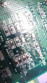
Seems I killed this one, I done a little bit of damage on the back around the 470uf axial cap. I'll attach some pictures.
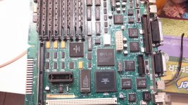
Happy Chime
Still black screen
Death Chimeeeeeee (it was very long)
Flash of a Horizontal line
I turned it off then turned it back on. Nothing just dead...
Seems I killed this one, I done a little bit of damage on the back around the 470uf axial cap. I'll attach some pictures.
I cant see the second pic, its too blurry.
The first one looks like it has too much solder on it. Just desolder the cap, clean out the hole and put the cap back in with less solder.
I also see some SMD/SMT caps with too much solder on them as well, particularly C3 to C7.
The first one looks like it has too much solder on it. Just desolder the cap, clean out the hole and put the cap back in with less solder.
I also see some SMD/SMT caps with too much solder on them as well, particularly C3 to C7.
ive been working on dead SE/30 boards over the last couple days. You may have created multiple problems here. One:
You lost an address line. You have to grab the schematics and start testing for shorted/open address lines back to the ROM SIMM from the peripheral ICs.
Keep in mind A0, and A1 is not on the ROM SIMM, but you can pick them up at the GLU.
These lines usually break around the ASC, and the SCSI ICs. I have also seen them break between the SCSI and SWIM, but that wont stop it from powering on.
Two:
Also the video will generate the initial state of the VRAM. Depending on the manufacturer of the VRAM, youll have zebra stripes, checkers, classic simasimac, depends on who made the VRAM wil depend on what shows on the screen.
But if you have nothing on the screen, start at UE8.
You lost an address line. You have to grab the schematics and start testing for shorted/open address lines back to the ROM SIMM from the peripheral ICs.
Keep in mind A0, and A1 is not on the ROM SIMM, but you can pick them up at the GLU.
These lines usually break around the ASC, and the SCSI ICs. I have also seen them break between the SCSI and SWIM, but that wont stop it from powering on.
Two:
Also the video will generate the initial state of the VRAM. Depending on the manufacturer of the VRAM, youll have zebra stripes, checkers, classic simasimac, depends on who made the VRAM wil depend on what shows on the screen.
But if you have nothing on the screen, start at UE8.
I would like to point out that I cleaned the board really well but there is a lot of sticky crap on the board, possibly from the solder? I tried cleaning it twice but its hard to come off. Would this cause a problem?
Sticky stuff on the board? Did you clean each cap area after removing the caps and before putting in the new cap and solder it?
If yes, then thats just Rosin Flux from the solder, which can be hard to remove but alcohol and/or acetone can be used with some hard rubbing to remove it. I use alcohol for Rosin, and a lot of cotton balls and q-tips. But Rosin should not effect now the machine boots. Its non-conductive when its a solid and only help for solder to cling to a metal surface when in its liquid state.
If yes, then thats just Rosin Flux from the solder, which can be hard to remove but alcohol and/or acetone can be used with some hard rubbing to remove it. I use alcohol for Rosin, and a lot of cotton balls and q-tips. But Rosin should not effect now the machine boots. Its non-conductive when its a solid and only help for solder to cling to a metal surface when in its liquid state.
Yes. I cleaned the pads with wick and then scrubbed the areas with a tooth brush and alcohol.
So its Rosin, nothing to worry about. Strong Alcohol and hard rubbing can clean that up.
I'm hoping its just the 470uf cap that I messed up on cause I got the board a little too hot. I need to get me a new tip.
Well I got my new soldering iron tips today so I decided to try to get this thing going again, no luck. On the back of the board I found a bridged solder joint. Fixed that, and I touched up some of the areas I damaged around that 470uf cap on the back side. Everything tested good on my meter. I figured it was just the bridged joint that caused the problem since the board worked before I recapped it... Flip the switch and I get a fan. still no picture, no bong, no death chime like before. Probably killed this one.
TechKnight, could you verify what my eyes are seeing in the original pic? Under the Battery Box, right of the ROM SIMM, D1 and D2 look like they are solder bridged over.
Snake88USA, one step at a time. Like I asked TechKnight - look at D1 and D2. If they are bridge-soldered over put some solder braid and flux to remove it. On my SE/30 board it should be 3 solder points on those two things. And Snake - you got the same can-style caps to recap the board? Check your caps and see that the solder is not shorting out against the can. Remove solder as needed to clear the can without desoldering the cap.
Snake88USA, one step at a time. Like I asked TechKnight - look at D1 and D2. If they are bridge-soldered over put some solder braid and flux to remove it. On my SE/30 board it should be 3 solder points on those two things. And Snake - you got the same can-style caps to recap the board? Check your caps and see that the solder is not shorting out against the can. Remove solder as needed to clear the can without desoldering the cap.
Can someone look at L21 and C62. Is it suppose to be like that?
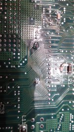
yup i have seen that a few times.
Well I am going to pull it back out tonight and take some better pics and try to figure out whats going on. Instead of starting another topic, I decided to boot up my other SE/30 last night. Still boots but a solid Hard Drive light and then flashes the floppy icon. Turned it off and turned it back on, the hard drive led is blinking but it almost instantly goes to a flashing question mark. I also had problems before getting some errors while copying floppies. Hard Drive crapped out or time for some more work on this board too?
I dont see any bridging. Everything looks ok. Besides, all this handles is the battery connection to the RTC.
The issue with the hard dive sounds like bad boot blocks, mostly a software issue. Do you have a Boot Floppy Disk with Disk First Aid or Norton's Emergency Boot Disk? Run Disk First Aid or Norton when it boots up.
The Floppy drive is harder to diagnose, as it can range from a misaligned or broken heads, floppy drive needs to be cleaned out, bad floppies, or Bournes Filter has crapped out.
Update. Maybe the board isn't even getting power? Even though the fan turns, I thought the monitor would glow from the back even though its not displaying a picture? I have the back off. Only thing getting power is the fan. Guess I could check to see if the board is getting power or not.
Check the connector with a multimeter.
In the very least "-" on the multimeter goes to black (Ground) and "+" on the mutlimeter goes to the yellow or orange which should read 12V and red which should read 5V. You can read these from the hard drive power connector.
In the very least "-" on the multimeter goes to black (Ground) and "+" on the mutlimeter goes to the yellow or orange which should read 12V and red which should read 5V. You can read these from the hard drive power connector.
Scratch what I said. This has to be a very quiet se lol. With the case off I can hear the speaker pop and its so hard to see but the monitor does glow. Time to poke around. Probably UE8?
I say, take out the board and without power start looking at the area of U3 - U6 with a magnifying glass and check out the traces and see if any are visibly broken. Compare it to a schematic and repair what broken traces you find. Then do the same thing with the large chips by C8 - C10 by the power connector.
In the tiny world, I think I see two pins connected on UE8.
I inspected the board and didn't find anything else. Everything looks fine. I especially checked the area where I damaged the board. Everything seems like its fine still. Checked with my meter and can't find anything wrong.
what voltages are you getting? 12 5 -5 ?
did you wash your MB? -- fully submerse it and scrub the cap goo out of all the I/C? and then give it a nice compressor dry?
and maybe a nice bake in the oven preheat at 190f for 15/20 minutes?
oh and again what is it doing when you power it on? make sure your ram and rom simms are mechanical clicked in properly.
for any goo that is tough to get, you can use acetone and a toothbrush.
did you wash your MB? -- fully submerse it and scrub the cap goo out of all the I/C? and then give it a nice compressor dry?
and maybe a nice bake in the oven preheat at 190f for 15/20 minutes?
oh and again what is it doing when you power it on? make sure your ram and rom simms are mechanical clicked in properly.
for any goo that is tough to get, you can use acetone and a toothbrush.
I tested voltage from the connector to the main board. I wash the motherboard with alcohol and scrubbed it good with a tooth brush. I then used canned air on it.
The first time after recap:
Black screen, Startup chime, death chime (repeated), Horizontal line flashed on the screen.
I turned it off and turned it back on, no chime at all.
Now the only thing that I know works is the fan, the hard drive comes on, and I can hear a pop from the speaker.
The first time after recap:
Black screen, Startup chime, death chime (repeated), Horizontal line flashed on the screen.
I turned it off and turned it back on, no chime at all.
Now the only thing that I know works is the fan, the hard drive comes on, and I can hear a pop from the speaker.
Ah, so can you take some high resolution , a well-lit photo of the whole main board front and back, maybe we will be able to see something.
other wise i doubt there is any thing else we can really help you with on this. Other then sending it to someone.
other wise i doubt there is any thing else we can really help you with on this. Other then sending it to someone.
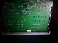
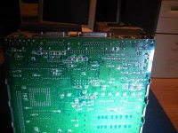
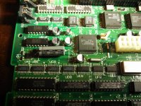
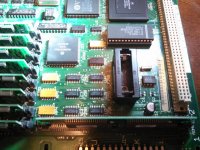
Inspect your C2 connection closely. Appears to have a short to the adjacent trace.
If so, it likely blew something up.
If so, it likely blew something up.