

Thread
Macintosh Portable 34 pin to 50 pin SCSI cable
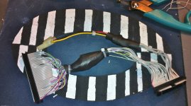
its: 4:16am OK Revision 3.0 this one works...
Its a little crude, but it works...
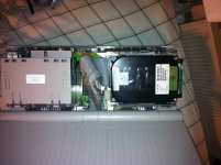

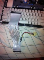
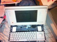
Its a little crude, but it works...
Please tell me you can recreate it as I need two 
yes,
The wife and I are going to sit down and come up with a method of production.
Now that we have one working, and know exactly what to do to make it work.
This first one is going to hap. he's in desperate need.
The wife and I are going to sit down and come up with a method of production.
Now that we have one working, and know exactly what to do to make it work.
This first one is going to hap. he's in desperate need.
1) Get two pieces of wood the appropriate lengths . . .
. . . with enough extra to clamp it to the work surface if you can still get the connector on the clamp end into your vise.
2) Epoxy headers and a MOLEX receptacle in the perfect positions on one board.
3) Make a slitting diagram on the second piece of wood with enough room to staple or clamp the ends of your ribbon cable at the ends.
4) Make slots in a piece of cardboard to mark the cable appropriately, with holes to register it over pins in the slitting board
Then do your wire slitting at one workstation . . .
. . . mount your IDCF connectors on the headers on the other workstation . . .
. . . do your cable fabrication/temporary punchdown & soldering . . .
. . . remove the fab jig . . .
. . . do your final punchdown on the vise . . .
Bonus points for setting up the boards/jigs at comfortable angles on a larger assembly jig the width of your table with the vise bolted to one side that hangs off the end of the table for bolt clearance. If you don't want to/can't clamp the production station board to the table, just make it enough larger to use 1x2 stock to make a rim/frame to fit around the table and pile a couple of cinder blocks on top during production . . .
Dunno . . . just off the top of my head . . .
. . . with enough extra to clamp it to the work surface if you can still get the connector on the clamp end into your vise.
2) Epoxy headers and a MOLEX receptacle in the perfect positions on one board.
3) Make a slitting diagram on the second piece of wood with enough room to staple or clamp the ends of your ribbon cable at the ends.
4) Make slots in a piece of cardboard to mark the cable appropriately, with holes to register it over pins in the slitting board
Then do your wire slitting at one workstation . . .
. . . mount your IDCF connectors on the headers on the other workstation . . .
. . . do your cable fabrication/temporary punchdown & soldering . . .
. . . remove the fab jig . . .
. . . do your final punchdown on the vise . . .
Bonus points for setting up the boards/jigs at comfortable angles on a larger assembly jig the width of your table with the vise bolted to one side that hangs off the end of the table for bolt clearance. If you don't want to/can't clamp the production station board to the table, just make it enough larger to use 1x2 stock to make a rim/frame to fit around the table and pile a couple of cinder blocks on top during production . . .
Dunno . . . just off the top of my head . . .
the wife is color coding them for me
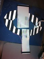
I find either way you do it, making these is quite time consuming.
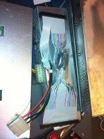
revision #4
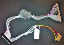
Also, with this 72gb u320 2.5" drive project i have been working on.
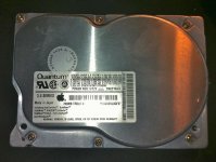
Managed to pull the 700mb Quantum out of my PM 6100 and install the new kind.
anyways looking at the original 40mb Conner HD it says +12 250ma / +5 275ma
Well this 700mb drive from the PM 6100 says +12 210ma / +5 200ma
So I would assume this newer more energy friendly drive would be a good choice.
takes the wife 20 min to color code
takes me about 1:20 to solder all the wires on
Also this thread I installed a SCSI Internal ZIP 100mb, seems to work out good.
viewtopic.php?f=10&t=21236
Also, with this 72gb u320 2.5" drive project i have been working on.
Managed to pull the 700mb Quantum out of my PM 6100 and install the new kind.
anyways looking at the original 40mb Conner HD it says +12 250ma / +5 275ma
Well this 700mb drive from the PM 6100 says +12 210ma / +5 200ma
So I would assume this newer more energy friendly drive would be a good choice.
takes the wife 20 min to color code
takes me about 1:20 to solder all the wires on
Also this thread I installed a SCSI Internal ZIP 100mb, seems to work out good.
viewtopic.php?f=10&t=21236
I didn't realize you were cutting and splicing every wire until I saw the color coding piccie. Why did you decide to splice the connections rather than rearranging the uncut wires on the IDC34F side?
because hap is going to sell these on ebay, and I need the IDC's to be solid, those idc are mechanically designed to be crimped to a cable not cut wires.
I don't want some big monkey fingers ripping out the wires after the first day.
I don't want some big monkey fingers ripping out the wires after the first day.
just i just thought of a good idea??
What if i epoxy'd the IDC's together after I pop the wires on?? hummmmm
no doubt popping the wires on the 34 pin side would be easier!
What if i epoxy'd the IDC's together after I pop the wires on?? hummmmm
no doubt popping the wires on the 34 pin side would be easier!
No need, folks have been reworking ribbon cables on existing harnesses for as long as IDC has been around. I you're going into production, just buy new connectors and ribbon cable. Get the three part connectors with the double-back strain relief setup. I missed you request for a new graphic, I'll work on that, as well as a diagram for an assembly jig setup.
I've got some time, the major hacks are at the awaiting parts acquisition stage again. : I'll do a diagram before I do the 'ole Scrooge MacDuck dive into the 21" high pile of 1400s. Gotta prune that back to a reasonable height of unborken lids attached to tricked out books . . .
. . . and a pile of spare parts for distribution. }
I've got some time, the major hacks are at the awaiting parts acquisition stage again. :
I'll do a diagram before I do the 'ole Scrooge MacDuck dive into the 21" high pile of 1400s. Gotta prune that back to a reasonable height of unborken lids attached to tricked out books . . .. . . and a pile of spare parts for distribution. }
Great!
Sounds good.

Sounds good.
I just did a local upload of the scanned doodle so I can print it out at work and muck it out a bit after I get back from dinner. 
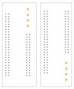
For the time being, I'm pretty happy with this cable.
Got some bigger shrink tube at harbor freight This one I made today, turned out pretty decent.
edit:
last one for the night.
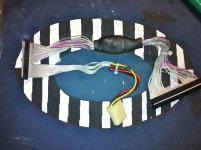
Got some bigger shrink tube at harbor freight This one I made today, turned out pretty decent.
edit:
last one for the night.
HEH!! }
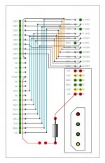
That one looks a lot more presentable, uni,
That one looks a lot more presentable, uni,
nice!, is that a fuse in there?
THX, uni, it went a bit easier than I'd thought it might. This is the first time I've done the criss-cross on opposite layers.
I think it's a resistor to limit the Termination Power current, but it might be something else, gotta figure that out from the boards I've now got in hand.
p.s. can you click to get the full size image? It usually takes a while before I can view the full size.
I think it's a resistor to limit the Termination Power current, but it might be something else, gotta figure that out from the boards I've now got in hand.
p.s. can you click to get the full size image? It usually takes a while before I can view the full size.
is the full size image 700+ x 1150 + ?
Sounds right, I cleared my cache and now I can see it too. I figured as much, when I place attachments, I'll have to be careful about how I do it or clear my cache. I'm guessing that previews are a no-no.
If anyone spots a boo-boo, lemme know.
If someone wants to critique the layout, PLEASE do!
If someone knows how to add an LED activity circuit, that'd be very cool, I'll add it in.
If anyone knows the right component for the TERMPWR jumper circuit, I'll add that info into the diagram as well.
If someone wants to make a production file for Seeeding some boards, I'd be thrilled, I want a pair!
Like I said on the first page, this would make a great community project! :approve:
I especially like the notion of doing a mounting sled for laptop drives or a board that'll easily bolt up to a 2.5" SCA adapter. For the former, I've got an APS external 2.5" HDD case. For the latter there are several permutations to consider.
I can't imagine that the little SCA Drives we've been playing with and a tiny muffin fan could possibly use as much power as the big honking OEM drives. :?:
If anyone spots a boo-boo, lemme know.
If someone wants to critique the layout, PLEASE do!
If someone knows how to add an LED activity circuit, that'd be very cool, I'll add it in.
If anyone knows the right component for the TERMPWR jumper circuit, I'll add that info into the diagram as well.
If someone wants to make a production file for Seeeding some boards, I'd be thrilled, I want a pair!
Like I said on the first page, this would make a great community project! :approve:
I especially like the notion of doing a mounting sled for laptop drives or a board that'll easily bolt up to a 2.5" SCA adapter. For the former, I've got an APS external 2.5" HDD case. For the latter there are several permutations to consider.
I can't imagine that the little SCA Drives we've been playing with and a tiny muffin fan could possibly use as much power as the big honking OEM drives. :?:
The 2.5" SCA drives draw too much power.
Some of the full size more modern hd's 800mb - 1gb consume less power then the 40mb Connor.
(As in my above post) the modern drives are quieter.
I just realized there might not be enough room in that area for a patch pcb,
so off the bat it would have to be kind of like the sca adaptors,
where the pcb pops right on to the hard drive and the 30 pin cable would make the whole stretch to the adaptor.
I suppost you could make 2 revisions, SCSI 2.5, SCSI 3.5,
Then one could just use a standard PC-Floppy cable to connect the PCB.
well they would have to hack of the end that flips pins for floppy 2.
Some of the full size more modern hd's 800mb - 1gb consume less power then the 40mb Connor.
(As in my above post) the modern drives are quieter.
I just realized there might not be enough room in that area for a patch pcb,
so off the bat it would have to be kind of like the sca adaptors,
where the pcb pops right on to the hard drive and the 30 pin cable would make the whole stretch to the adaptor.
I suppost you could make 2 revisions, SCSI 2.5, SCSI 3.5,
Then one could just use a standard PC-Floppy cable to connect the PCB.
well they would have to hack of the end that flips pins for floppy 2.
Interesting, how far over budget are the SCA drives?
I've got the 50 pin connector flopped to the other side of the board on the layout. If I'm looking at the correctly, a 3.5" HDD will plug into the bottom of the adapter just like the SCA Drives do and the IDC34 cable will plonk onto their headers behind that in the same manner.
I've got the info for putting the 40 pin 2.5" SCSI drive socket opposite the 50 pin connector. I'll do that so the 2.5" drive will plug into the "other bottom" of the adapter exactly like the 2.5" SCA drives do.
Only one adapter PCB to adapt either type of drive, as necessary.
Dunno if it'll work . . . I'll play with it in the AM . . . |)
I've got the 50 pin connector flopped to the other side of the board on the layout. If I'm looking at the correctly, a 3.5" HDD will plug into the bottom of the adapter just like the SCA Drives do and the IDC34 cable will plonk onto their headers behind that in the same manner.
I've got the info for putting the 40 pin 2.5" SCSI drive socket opposite the 50 pin connector. I'll do that so the 2.5" drive will plug into the "other bottom" of the adapter exactly like the 2.5" SCA drives do.
Only one adapter PCB to adapt either type of drive, as necessary.
Dunno if it'll work . . . I'll play with it in the AM . . . |)
well the original 40mb Connor hd is:
+12 - 250ma
+5 - 275ma
The IBM SCA Drive is
+12 - 800ma
+5 - 500ma
This newer scsi Quantum 700mb drive i have here is:
+12 - 210ma
+5 - 200ma
the 100mb scsi zip drive, witch works only because it does not use the 12v boost regulator just the +5v regulator
+5 - 800ma - but might still over heat the +5v regulator over time.
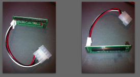
Yes to one PCB, -great idea Mr. Smarty pants. I have a 2.5 to 3.5 adaptor, but the power/data location config is non standard.
+12 - 250ma
+5 - 275ma
The IBM SCA Drive is
+12 - 800ma
+5 - 500ma
This newer scsi Quantum 700mb drive i have here is:
+12 - 210ma
+5 - 200ma
the 100mb scsi zip drive, witch works only because it does not use the 12v boost regulator just the +5v regulator
+5 - 800ma - but might still over heat the +5v regulator over time.
Yes to one PCB, -great idea Mr. Smarty pants. I have a 2.5 to 3.5 adaptor, but the power/data location config is non standard.
That's odd about the pinout, where did you get your 3.5"->2.5" Adapter? :?:
http://www.hardwarebook.info/SCSI_Internal_%282.5%22%29
There's power on both ends of that interface, did they lay out the connector out upside down or install the connectors backwards on the PCB? )
)
http://www.hardwarebook.info/SCSI_Internal_%282.5%22%29
There's power on both ends of that interface, did they lay out the connector out upside down or install the connectors backwards on the PCB?
)
Very strange HDD mounting tray/setup in the Portable. Why the centerline mounting holes for the HDD? This is not convenient at all! :-/
)
On a more serious note: you'd probably want to slit the lines on a PC FDD cable to match the original cable. Apple l could have folded the ribbon cable. It's not just easier to route the way it's done, it might help to keep crosstalk at bay to jumble the wires about like that on the way to the HDD since there don't appear to be enough lines for the alternate ground line method . . .
. . . or just use the original cable!
) On a more serious note: you'd probably want to slit the lines on a PC FDD cable to match the original cable. Apple l could have folded the ribbon cable. It's not just easier to route the way it's done, it might help to keep crosstalk at bay to jumble the wires about like that on the way to the HDD since there don't appear to be enough lines for the alternate ground line method . . .
I dont think corss-talk is going to be a concern @ 1.5mb / sec, or across 5 inches of cable 
Apple wasn't concerned with cross-talk with the original portable hd cable design, not sure why you would mention it now.
The 2.5 to 3.5" adaptor
I got it on ebay.
Apple wasn't concerned with cross-talk with the original portable hd cable design, not sure why you would mention it now.
The 2.5 to 3.5" adaptor
I got it on ebay.
I mentioned crosstalk on the first page of the thread and now I'm wondering about it again. The original cable is slitted and done up in a double ponytail deal with wire ties making one full twist overall. That's likely way better than a straight ribbon cable in terms of crosstalk, so they might have been thinking in those terms. I'm trying to cover all angles so I'm thinking out loud here in .TXT . . .
. . . and kidding around in retaliation for that "Mr. Smarty pants" crack.
Got linkage to that adapter?
. . . and kidding around in retaliation for that "Mr. Smarty pants" crack.
Got linkage to that adapter?
I just figured out how to convert a Cheap@$$ 3.5"->2.5" IDE converter to a Luggable 2.5" SCSI cable! ;D
1) Desolder the edge mounted IDC headers for the 3.5" connection.
2) Solder the slitted PC FDD cable's stripped ends to the proper positions on the "edge card connector" where the headers were.
4) Mount it off the end of the SCSI HDD's headers so that the old 2.5" IDE P & G connection sockets hang in the air.
The cheap SCA->50pin 3.5" SCSI connectors can probably be converter as well.
1) Bake & shake all the components off the board.
2) Lop the ends, both MOLEX and jumper headers, off the PCB.
3) Install a straight soldertail IDC50 plug opposite where the male connector was.
2) Solder the slitted PC FDD cable's stripped ends into the proper thru-hole positions for the SCA connector.
I'll have to complete the diagram I did to figure out the SCSI Voodoo of the SCA adapters to give you the "pinout" for the FDD wires.
I'm not sure that this will work physically, but it appears that the board is narrow enough to fit below the roof. Someone else is going to have to test it.
If I damage the stickers, it'll void the warranty on my Luggable's perfectly serviceable Hard Disk 40SC.
1) Desolder the edge mounted IDC headers for the 3.5" connection.
2) Solder the slitted PC FDD cable's stripped ends to the proper positions on the "edge card connector" where the headers were.
4) Mount it off the end of the SCSI HDD's headers so that the old 2.5" IDE P & G connection sockets hang in the air.
The cheap SCA->50pin 3.5" SCSI connectors can probably be converter as well.
1) Bake & shake all the components off the board.
2) Lop the ends, both MOLEX and jumper headers, off the PCB.
3) Install a straight soldertail IDC50 plug opposite where the male connector was.
2) Solder the slitted PC FDD cable's stripped ends into the proper thru-hole positions for the SCA connector.
I'll have to complete the diagram I did to figure out the SCSI Voodoo of the SCA adapters to give you the "pinout" for the FDD wires.
I'm not sure that this will work physically, but it appears that the board is narrow enough to fit below the roof. Someone else is going to have to test it.
If I damage the stickers, it'll void the warranty on my Luggable's perfectly serviceable Hard Disk 40SC.
i just got this aztechmonster thing to work,
its pretty cool, quite fast, uses almost no power.
Hap made this really great mounting plate with his CNC machine. Makes a flawless fit in the portable.
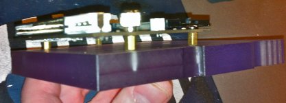
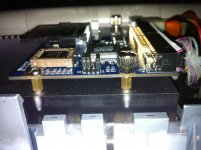
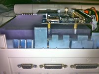
its pretty cool, quite fast, uses almost no power.
Hap made this really great mounting plate with his CNC machine. Makes a flawless fit in the portable.
not to thread jack, but the portable has a VGA connection?