

Thread
Macintosh Portable - video artifacts, does not boot
Non-backlit, 1MB memory, sys 6.0.7 (on floppy) HD did not work
Booted once when I first got it (after removing the HD), and I could not get it to start up after that.
So I took it apart, and quite a few of the caps were leaking. Just oily wetness and very minor corrosion around a few chip connections. The traces all appeared to be untouched.
Now, after the recapping (pretty sure that went well - no issues were apparent anyway) here is what I see, hopefully someone can point me to what may be the cause (or a schematic) and I can go from there...
With 3A 7.5v adapter plugged in, no main battery, 9v backup in and the lid to the battery compartment closed, all things plugged in but the HD.
1) Pressing a key on the keyboard, the machine makes noise and the screen goes to a pattern that has some light in it, the disk drive makes a brief noise, then the pattern goes to a 50% vertical and then stays there.
a) Resetting the machine with just the reset switch makes a crackly sound in the speaker, but nothing else. Pressing the interrupt switch does nothing.
b)Pressing both the interrupt and reset switches resets to a blank, clear screen.
2) Pressing a key on the keyboard, the disk drive makes a brief noise, goes again to a dark screen that slowly clears (from R to L) to a 50% grey over a couple of minutes.
Starting without the floppy drive makes no difference except that the floppy drive noise is absent. -otherwise all is the same.
I have visually rechecked the solder joints, but I will check with continuity later.
I tried washing the board (It is drying now). Before, I had only spot cleaned with 98% Alcohol, prior to recapping.
Any ideas or other suggestions?
Booted once when I first got it (after removing the HD), and I could not get it to start up after that.
So I took it apart, and quite a few of the caps were leaking. Just oily wetness and very minor corrosion around a few chip connections. The traces all appeared to be untouched.
Now, after the recapping (pretty sure that went well - no issues were apparent anyway) here is what I see, hopefully someone can point me to what may be the cause (or a schematic) and I can go from there...
With 3A 7.5v adapter plugged in, no main battery, 9v backup in and the lid to the battery compartment closed, all things plugged in but the HD.
1) Pressing a key on the keyboard, the machine makes noise and the screen goes to a pattern that has some light in it, the disk drive makes a brief noise, then the pattern goes to a 50% vertical and then stays there.
a) Resetting the machine with just the reset switch makes a crackly sound in the speaker, but nothing else. Pressing the interrupt switch does nothing.
b)Pressing both the interrupt and reset switches resets to a blank, clear screen.
2) Pressing a key on the keyboard, the disk drive makes a brief noise, goes again to a dark screen that slowly clears (from R to L) to a 50% grey over a couple of minutes.
Starting without the floppy drive makes no difference except that the floppy drive noise is absent. -otherwise all is the same.
I have visually rechecked the solder joints, but I will check with continuity later.
I tried washing the board (It is drying now). Before, I had only spot cleaned with 98% Alcohol, prior to recapping.
Any ideas or other suggestions?
what kind of caps did you use for the 16v47u ones? and the 50v1uf? and the 16v10uf?
also did you change all the radials?
also did you change all the radials?
These are what I replaced; second column lists the replacement cap.
Replaced with Electrolytic/Radial
C2 100uF 25v ->100uF 50v
C6 100uF 25v -> 100uF 50v
C18 100uF 25v -> 100uF 50v
C19 100uF 25v -> 100uF 50v
C3 220uF 25v -> 220uF 35v
Electrolytic/Axial
C8 470uF 25v -> 470uF 50v
C16 470uF 25v -> 470uF 50v
C20 470uF 25v -> 470uF 50v
Replaced all these withTantalums
47's with same voltage
could not find 50v for the 1uF locally,
I had some 35v ones laying about that I used.
C9 47uF 16v
C10 47uF 16v
C11 47uF 16v
C17 47uF 16v
C22 47uF 16v
C25 47uF 16v
C26 47uF 16v
C27 47uF 16v
C28 47uF 16v
C14 10uF 16v -> 10uF 20v
---- 10uF 16v -> 10uF 20v
C4 1uF 50v -> 10uF 35v
C5 1uF 50v -> 10uF 35v
C15 1uF 50v -> 10uF 35v
C24 1uF 50v -> 10uF 35v
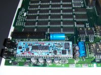
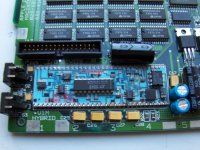
Replaced with Electrolytic/Radial
C2 100uF 25v ->100uF 50v
C6 100uF 25v -> 100uF 50v
C18 100uF 25v -> 100uF 50v
C19 100uF 25v -> 100uF 50v
C3 220uF 25v -> 220uF 35v
Electrolytic/Axial
C8 470uF 25v -> 470uF 50v
C16 470uF 25v -> 470uF 50v
C20 470uF 25v -> 470uF 50v
Replaced all these withTantalums
47's with same voltage
could not find 50v for the 1uF locally,
I had some 35v ones laying about that I used.
C9 47uF 16v
C10 47uF 16v
C11 47uF 16v
C17 47uF 16v
C22 47uF 16v
C25 47uF 16v
C26 47uF 16v
C27 47uF 16v
C28 47uF 16v
C14 10uF 16v -> 10uF 20v
---- 10uF 16v -> 10uF 20v
C4 1uF 50v -> 10uF 35v
C5 1uF 50v -> 10uF 35v
C15 1uF 50v -> 10uF 35v
C24 1uF 50v -> 10uF 35v
I was pretty sure there were more caps than on that corner. My only suggestion as I did it to a Mac II video card ( my first recap ) that the polarity should be rechecked and replace all caps. After Uni did my portable it booted straight away upon return to me.
That Hybrid IC has issues, if you look close at the 8 pin IC, theres 2 pins that looked burned as if too much current has flown through it. Something is wrong...
Yes, there are way more, I just posted a representative before and after picture.
Thanks for the advice, I don't relish re-re-capping the board, but it may come to that.
Technight - thanks, I thought it looked a bit funny, there are a few more areas that looked overheated there, not sure what I can do for that...
Thanks for the advice, I don't relish re-re-capping the board, but it may come to that.
Technight - thanks, I thought it looked a bit funny, there are a few more areas that looked overheated there, not sure what I can do for that...
You can't change 1uf 50v caps with 10uf 35v, voltage can be higher as the original one but not the capacitance.
Yea, you want to use the same values, and voltage should not be less either.
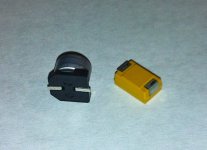
also, a good example is C28 there in the picture (and) using tantalums.
The pad configuration on the pcb is not for tantalum caps. so you have to be careful, not only does the leaky goo from caps cause corrosion, but it gets between the PCB and the epoxy, and causes the epoxy to flake/peel off. Then when you use tants, and then over solder as well, it can cause solder bridges.
also, a good example is C28 there in the picture (and) using tantalums.
The pad configuration on the pcb is not for tantalum caps. so you have to be careful, not only does the leaky goo from caps cause corrosion, but it gets between the PCB and the epoxy, and causes the epoxy to flake/peel off. Then when you use tants, and then over solder as well, it can cause solder bridges.
C4 1uF 50v -> 1uF 35v
C5 1uF 50v -> 1uF 35v
C15 1uF 50v -> 1uF 35v
C24 1uF 50v -> 1uF 35v
Sorry for the disinformation - these were supposed to say 1uF (they were replaced with ones, just a copy paste typo) - they are lower voltages than the 50, that is still an issue and what I was trying to draw attention to ...I checked that twice before I posted it and still got it wrong.
Normally I re-tin the pads and the caps, prior to soldering them and I have had pretty good luck with the se/30's (and some Tandy's that I did previously), but the IICX I last did had traces that were bad from the corrosion and this one has something that is not quite right. Might try sending it off to Uniserver (to have a look or re-re-recap?) in a week or two if I can't hash it out.
C5 1uF 50v -> 1uF 35v
C15 1uF 50v -> 1uF 35v
C24 1uF 50v -> 1uF 35v
Sorry for the disinformation - these were supposed to say 1uF (they were replaced with ones, just a copy paste typo) - they are lower voltages than the 50, that is still an issue and what I was trying to draw attention to ...I checked that twice before I posted it and still got it wrong.
Normally I re-tin the pads and the caps, prior to soldering them and I have had pretty good luck with the se/30's (and some Tandy's that I did previously), but the IICX I last did had traces that were bad from the corrosion and this one has something that is not quite right. Might try sending it off to Uniserver (to have a look or re-re-recap?) in a week or two if I can't hash it out.
no problem i can help-
my only issue right now is that I do not own a portable to test it.
soon i would like to have one though
my only issue right now is that I do not own a portable to test it.
soon i would like to have one though
If it helps explain your issue mine had the same issue before recap. So either a cap may not be connected or backwards. Also if you sent just the motherboard the screen keyboard and the power harness I am sure uni could at least test the unit. The interlock can be closed and just plug in a powerbook 100 series plug and hit a key on the keyboard to boot. that way its not too heavy to ship, doesnt need a mouse, floppy or hard disk to show its working.
Good Luck.
Good Luck.
hello did you end up getting this to work?
Nope, I haven't. I will be sending the board your way sometime soon. Macdrone's suggestion is actually the way that I have been testing (no point in stressing plastic tabs over and over again). If that will work for you, I'll just include the extra pieces to test with.
I'll PM you when I get time to pack things up, if that's ok.
I'll PM you when I get time to pack things up, if that's ok.
Sure, pm me when you are ready , I hope to have a portable of my own soon