

Thread
Compact Mac retina display
The schematic is in Post #5 in this thread, based on the principles at the link in Post #2. It's taken a while for me to understand how these flyback circuits work because the principles are pretty different from other amplifier circuits. (I do have a background in analog electronics, but not many people work closely with inductors and transformers anymore, unless building switching power converters.)
A Class-AB amp will work great for the vertical deflection (and I think that's what is there now) but the horizontal is too fast, with too high of a voltage during retrace to generate easily. I'm sure it's possible, but it would run pretty hot.
But studying these old circuits you come to admire the cleverness of what people came up with with very limited means. With just a single switching transistor, the sawtooth generates itself! While the transistor is on, you get +Vcc across the inductor, which creates a linear ramp in current. When the transistor switches off (retrace) that current has to go somewhere so it charges the capacitor (C12) and rings for a half-cycle, during which time the direction of the current reverses.
The DC offset comes, I think, from the losses in the system. If there were no resistance anywhere, the ringing would be perfect and at the end of the retrace period, the current in the yoke would be exactly equal and opposite to where it started. But some of it is lost to resistance (heat) so it ends up with a slightly smaller current in the negative direction compared to the positive. Averaged over time, the net result is a DC offset. It's not huge, maybe 10% of the total, but as you say it's heat that we don't need!
This doesn't happen in the regular SE/30 analog board because of C15 (nonpolar 3.9uF cap), which blocks DC current. But (as I understand it), to use a cap in my simplified circuit, the whole operation needs to be driven from something resembling a current source rather than a voltage source. I think the way it works on the analog board is that the flyback primary is a big inductor, probably bigger than the yoke, so Q2 does effectively see a constant current from it. But the full operation of the transformer is still a bit confusing. And in any case, the whole point is to get rid of the flyback, so I'll need to find a different solution.
Interesting idea on the HV caps! Sounds possibly a bit hazardous though.
A Class-AB amp will work great for the vertical deflection (and I think that's what is there now) but the horizontal is too fast, with too high of a voltage during retrace to generate easily. I'm sure it's possible, but it would run pretty hot.
But studying these old circuits you come to admire the cleverness of what people came up with with very limited means. With just a single switching transistor, the sawtooth generates itself! While the transistor is on, you get +Vcc across the inductor, which creates a linear ramp in current. When the transistor switches off (retrace) that current has to go somewhere so it charges the capacitor (C12) and rings for a half-cycle, during which time the direction of the current reverses.
The DC offset comes, I think, from the losses in the system. If there were no resistance anywhere, the ringing would be perfect and at the end of the retrace period, the current in the yoke would be exactly equal and opposite to where it started. But some of it is lost to resistance (heat) so it ends up with a slightly smaller current in the negative direction compared to the positive. Averaged over time, the net result is a DC offset. It's not huge, maybe 10% of the total, but as you say it's heat that we don't need!
This doesn't happen in the regular SE/30 analog board because of C15 (nonpolar 3.9uF cap), which blocks DC current. But (as I understand it), to use a cap in my simplified circuit, the whole operation needs to be driven from something resembling a current source rather than a voltage source. I think the way it works on the analog board is that the flyback primary is a big inductor, probably bigger than the yoke, so Q2 does effectively see a constant current from it. But the full operation of the transformer is still a bit confusing. And in any case, the whole point is to get rid of the flyback, so I'll need to find a different solution.
Interesting idea on the HV caps! Sounds possibly a bit hazardous though.
Well, I am wondering if maybe a Class-D or even a Class-GH setup for the horizontal winding. GH keeps it analog but steps the voltage to reduce the heat produced in the output stage.
AB as it is could be a massive heat producer because the frequencies at which it needs to operate at. BUT... using class D, its doable, And you can cleverly design the output stage to allow the yoke to be part of the low-pass inductor circuit and it too will generate its own ramp.
Who knows.. possibilities are endless here, thats the fun part!
Or... your original circuit you could add a transistor as a high-side switch to the yoke keeping it disconnected until required for the dwell period. Thats another option.
I noticed on the original design the yoke is ground-side connected, and your new little circuit its high side connected, wondering if maybe that is an issue?
I dunno, maybe toy around with some fun things.
AB as it is could be a massive heat producer because the frequencies at which it needs to operate at. BUT... using class D, its doable, And you can cleverly design the output stage to allow the yoke to be part of the low-pass inductor circuit and it too will generate its own ramp.
Who knows.. possibilities are endless here, thats the fun part!
Or... your original circuit you could add a transistor as a high-side switch to the yoke keeping it disconnected until required for the dwell period. Thats another option.
I noticed on the original design the yoke is ground-side connected, and your new little circuit its high side connected, wondering if maybe that is an issue?
I dunno, maybe toy around with some fun things.
First resolution-changing experiments!
I decided the best way to test different resolutions with the existing display was to keep the 1-bit video circuits for now and build a high-speed comparator circuit to turn a VGA-level signal into a logic output. I used an AD8561 comparator for this, with an adjustable threshold set somewhere in the middle of the grayscale range.
I also built another one-shot 74LS123 circuit for the vertical sync pulse, because my measurements showed that VSYNC is low for only about 50-60us on most resolutions, compared to the 180us on the SE/30 display. Vertical retrace isn't usually that short so the 74LS123 extends the pulse to a length up to maybe 150us.
After a bit of surgery on the traces around P4 on the analog board, this was the result driving from VGA resolution on a Quadra 650 (still using the SE/30 logic board HSYNC signal to drive the flyback; I'll look at phase locking later):
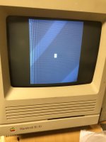
Not bad, though not great either. The geometry of the image is pretty good, though even with no delay at all on HSYNC, there is a foldover problem-- the video line starts too soon. The reason for this is that the retrace time on the yoke circuit is too long. It was 4.6us, which depends on the series inductance of the yoke and the width coil (L2), and the value of the flyback capacitor C12, 25nF in this case.
There are two ways to shorten this. One is to make C smaller, which I did, reducing it down to 15nF. The other is to get rid of the width coil which I'd previously measured at about 25% of the inductance of the yoke itself. There's no reason to use the width coil in this circuit anyway, since the supply voltage determines the picture width. (In fact, the later Classic analog boards don't use a variable inductor for width either.)
So replacing L2 with a short circuit and C12 with 15nF, I got this:
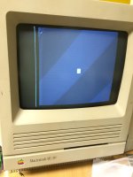
Getting there! To get a wider picture I will need a power supply of greater than 20V, and also I'll need to replace the HOT with something that can withstand more voltage. I'm thinking of building a MOSFET circuit like in the Classic analog boards, which will also have the advantage of getting rid of a custom Apple transformer.
More immediately, though, the video looks a little wonky. There's that bright line on the left side of the screen, which actually only appears when the supply voltage (i.e. width) is large. I'm pretty sure it's some sort of interference between the high-voltage pulse on the yoke and the millivolt-level high-speed comparator circuit. I built all this stuff onto a PCB and everything is bypassed correctly, but there's still a bunch of long wires stringing all over the place from SE/30 to yoke driver to sync/video circuits. Not really ideal for high-speed stuff like this.
Related is the vertical stripes in the video near the left. I'm pretty sure this is also some signal superimposed on the comparator, or a result of running a long single wire from my board to the SE/30 carrying the 25MHz video signal.
The geometry is great though! This really makes me think this can work once it's all properly cleaned up.
I decided the best way to test different resolutions with the existing display was to keep the 1-bit video circuits for now and build a high-speed comparator circuit to turn a VGA-level signal into a logic output. I used an AD8561 comparator for this, with an adjustable threshold set somewhere in the middle of the grayscale range.
I also built another one-shot 74LS123 circuit for the vertical sync pulse, because my measurements showed that VSYNC is low for only about 50-60us on most resolutions, compared to the 180us on the SE/30 display. Vertical retrace isn't usually that short so the 74LS123 extends the pulse to a length up to maybe 150us.
After a bit of surgery on the traces around P4 on the analog board, this was the result driving from VGA resolution on a Quadra 650 (still using the SE/30 logic board HSYNC signal to drive the flyback; I'll look at phase locking later):
Not bad, though not great either. The geometry of the image is pretty good, though even with no delay at all on HSYNC, there is a foldover problem-- the video line starts too soon. The reason for this is that the retrace time on the yoke circuit is too long. It was 4.6us, which depends on the series inductance of the yoke and the width coil (L2), and the value of the flyback capacitor C12, 25nF in this case.
There are two ways to shorten this. One is to make C smaller, which I did, reducing it down to 15nF. The other is to get rid of the width coil which I'd previously measured at about 25% of the inductance of the yoke itself. There's no reason to use the width coil in this circuit anyway, since the supply voltage determines the picture width. (In fact, the later Classic analog boards don't use a variable inductor for width either.)
So replacing L2 with a short circuit and C12 with 15nF, I got this:
Getting there! To get a wider picture I will need a power supply of greater than 20V, and also I'll need to replace the HOT with something that can withstand more voltage. I'm thinking of building a MOSFET circuit like in the Classic analog boards, which will also have the advantage of getting rid of a custom Apple transformer.
More immediately, though, the video looks a little wonky. There's that bright line on the left side of the screen, which actually only appears when the supply voltage (i.e. width) is large. I'm pretty sure it's some sort of interference between the high-voltage pulse on the yoke and the millivolt-level high-speed comparator circuit. I built all this stuff onto a PCB and everything is bypassed correctly, but there's still a bunch of long wires stringing all over the place from SE/30 to yoke driver to sync/video circuits. Not really ideal for high-speed stuff like this.
Related is the vertical stripes in the video near the left. I'm pretty sure this is also some signal superimposed on the comparator, or a result of running a long single wire from my board to the SE/30 carrying the 25MHz video signal.
The geometry is great though! This really makes me think this can work once it's all properly cleaned up.
Finally, since it was all set up anyway, I tried a Mac 13" 640x480 signal (same resolution, 10% faster scan rate):
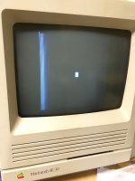
No problems on vertical sync at all (just like techknight predicted). The picture is a little shorter but could easily be adjusted with the trim that's already on the analog board. However, the checkerboard pattern has become very dark. 832x624 is even worse-- all you see is the floppy icon! I think the speed of the CRT video amplifier circuit will start to become a limitation here.
Which raises another question. Has anyone tried one of the Micron Xceed replica CRT boards that are for sale online? Not only would it be a useful eventual grayscale solution, but the amplifier might also have better bandwidth than the stock CRT board.
No problems on vertical sync at all (just like techknight predicted). The picture is a little shorter but could easily be adjusted with the trim that's already on the analog board. However, the checkerboard pattern has become very dark. 832x624 is even worse-- all you see is the floppy icon! I think the speed of the CRT video amplifier circuit will start to become a limitation here.
Which raises another question. Has anyone tried one of the Micron Xceed replica CRT boards that are for sale online? Not only would it be a useful eventual grayscale solution, but the amplifier might also have better bandwidth than the stock CRT board.
bandwidth on the neck board was an issue if I recall. But the circuit diagram of the Xceed neck board is available, so you could whip up a quick replica.
Anyways... for shits and giggles, try 512x384, which is the mac 12" RGB Resolution. As for increasing the voltage, Try a boost converter coil in the yoke circuit? Sure you have to calculate it out but with the correct value, the discharge on the coil should charge the voltage to drive the yoke. In normal circuitry, the flyback acts as this. But in your case you dont have that. So make one
If this means anything, I recall working on monitors way back in the day that had split-horiz systems. the horizontal yoke output, and flyback output were separate. And in all cases that I can recall, the horizontal yoke stage always had a SMPS-Sized transformer in there. either as a transformer, or as a coil. I cannot recall. But it was there. Projection TV sets come to mind. Mitsubishi, and Hitachi.
The issue your having with width could be the reason why they use horizontal output transformers. Maybe to Impedance match the yoke against the circuit, or as a charge-pump boost type thing.
Anyways... for shits and giggles, try 512x384, which is the mac 12" RGB Resolution. As for increasing the voltage, Try a boost converter coil in the yoke circuit? Sure you have to calculate it out but with the correct value, the discharge on the coil should charge the voltage to drive the yoke. In normal circuitry, the flyback acts as this. But in your case you dont have that. So make one
If this means anything, I recall working on monitors way back in the day that had split-horiz systems. the horizontal yoke output, and flyback output were separate. And in all cases that I can recall, the horizontal yoke stage always had a SMPS-Sized transformer in there. either as a transformer, or as a coil. I cannot recall. But it was there. Projection TV sets come to mind. Mitsubishi, and Hitachi.
The issue your having with width could be the reason why they use horizontal output transformers. Maybe to Impedance match the yoke against the circuit, or as a charge-pump boost type thing.
New question concerning the inverse: if standard video output is decoupled in the same manner and sync'd to the internal display, will overclocking the system bus to the point of FDD borkage become a possibility?
A little bit more progress. I added a voltage reference (TL431) in the video comparator circuit to get a more stable threshold and tightened up the wiring. That seems to have eliminated the vertical bars on the left side of the image.
For the video signal, I also took U1 (the 7438 NAND/inverter) out of the circuit and hooked up the video comparator output straight to its output. My guess was that the 7438 might be too slow for higher-res video. Removing it seems to have helped a bit with the dark image problem at higher resolutions.
Here's a VGA input now. The overall geometry is cleaner, but it actually makes some of the smaller imperfections more obvious:
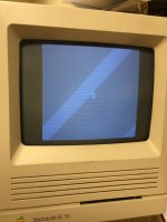
A couple notable issues. First, each video line starts in a slightly different place, which you can see when looking closely at the edge of the picture. Also, some lines are brighter than others which shows up as horizontal stripes in the image. One or both of these is probably now from the lack of phase lock between the flyback circuit and the yoke driver circuit. Some kind of PLL is probably the next step.
Here's 832x624 now. Still needs more width, and it has some rollover, but at least the video is visible:

techknight, that's a helpful piece of info on the split horizontal systems, specifically the fact that they all have an extra transformer or inductor. I wouldn't be surprised if it was just a straightforward inductor which serves the same function as the flyback primary in a combined system. I plan to do some experiments with adding an inductor for this purpose, which will let me add the DC-blocking capacitor (C15) back into the circuit. If that works it will get rid of the horizontal offset problem and save some wasted power.
For increasing the voltage, that just takes a different power supply. The benchtop supply I have right now tops out at 20V, but the circuit could easily be run at a higher voltage and will undoubtedly need to be for the higher resolutions.
I also just bought a Radius Pivot SE/30 PDS card (plus a IIsi Radius card and angle riser card) so once the higher res is working I should be able to drive it from the SE/30 itself rather than the external video source I'm using now.
For the video signal, I also took U1 (the 7438 NAND/inverter) out of the circuit and hooked up the video comparator output straight to its output. My guess was that the 7438 might be too slow for higher-res video. Removing it seems to have helped a bit with the dark image problem at higher resolutions.
Here's a VGA input now. The overall geometry is cleaner, but it actually makes some of the smaller imperfections more obvious:
A couple notable issues. First, each video line starts in a slightly different place, which you can see when looking closely at the edge of the picture. Also, some lines are brighter than others which shows up as horizontal stripes in the image. One or both of these is probably now from the lack of phase lock between the flyback circuit and the yoke driver circuit. Some kind of PLL is probably the next step.
Here's 832x624 now. Still needs more width, and it has some rollover, but at least the video is visible:
techknight, that's a helpful piece of info on the split horizontal systems, specifically the fact that they all have an extra transformer or inductor. I wouldn't be surprised if it was just a straightforward inductor which serves the same function as the flyback primary in a combined system. I plan to do some experiments with adding an inductor for this purpose, which will let me add the DC-blocking capacitor (C15) back into the circuit. If that works it will get rid of the horizontal offset problem and save some wasted power.
For increasing the voltage, that just takes a different power supply. The benchtop supply I have right now tops out at 20V, but the circuit could easily be run at a higher voltage and will undoubtedly need to be for the higher resolutions.
I also just bought a Radius Pivot SE/30 PDS card (plus a IIsi Radius card and angle riser card) so once the higher res is working I should be able to drive it from the SE/30 itself rather than the external video source I'm using now.
something more simple instead of using a PLL, use a programmable divider. so the flyback runs off of a divided frequency of the scan. Thats how alot of cheaper multisync monitors worked.
Yeah I think a simple divide-by-2 will work well for 832x624 (49.7kHz horizontal).
For Mac 640x480 (35.0kHz) or VGA (31.5kHz) it should probably be 3:2. Or at the least, there will need to be other changes to the flyback circuit to make it happy at 16-17kHz. Longer scan lines means more current and higher peak voltage during flyback, which could damage something. Have you done any experiments running this circuit with NTSC inputs? From previous discussion I take it the transformer itself is rated for it, but there would need to be other changes.
Before any of this, what I may do is run the flyback circuit off a signal generator and see how the CRT voltages change as the frequency goes up or down. I don't have the tools measure the anode voltage but the rest I could check, assuming they will all remain roughly proportional.
For Mac 640x480 (35.0kHz) or VGA (31.5kHz) it should probably be 3:2. Or at the least, there will need to be other changes to the flyback circuit to make it happy at 16-17kHz. Longer scan lines means more current and higher peak voltage during flyback, which could damage something. Have you done any experiments running this circuit with NTSC inputs? From previous discussion I take it the transformer itself is rated for it, but there would need to be other changes.
Before any of this, what I may do is run the flyback circuit off a signal generator and see how the CRT voltages change as the frequency goes up or down. I don't have the tools measure the anode voltage but the rest I could check, assuming they will all remain roughly proportional.
ive run it at NTSC frequencies, yes. but the horizontal output transistor ran much hotter.
you can grab a cheap high voltage probe on ebay. they are a necessity when servicing vintage CRT sets.
you can grab a cheap high voltage probe on ebay. they are a necessity when servicing vintage CRT sets.