

Thread
Ethernet MicroDock - any chance of repair?
A kind person gave me a Duo 210 along with a non-working (we think) Newer Technology Ethernet MicroDock a while ago. The Duo works great. I'd like to figure out if the MicroDock can be repaired.
The ADB port on it works fine, but I can't seem to get the ethernet to work. I installed the driver and it recognizes the dock, but when I plug it into a switch or hub, the link light doesn't come on and obviously no network traffic passes through. There is a self test feature you can run in their software that will test the media access control, encoder/decoder and transceiver. The media access control and encoder/decoder pass the test, but the transceiver test fails. I don't know if anything has to be plugged in for the transceiver test to pass. I'm curious if anyone else with one of these docks would know if all three tests usually pass on a working MicroDock with nothing plugged into it.
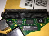
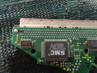
I cracked it open to look for anything obvious, but nothing really stands out. Any ideas where to even begin? Before anybody mentions it, because I know someone will, the MicroDock does not have any electrolytic capacitors
The ADB port on it works fine, but I can't seem to get the ethernet to work. I installed the driver and it recognizes the dock, but when I plug it into a switch or hub, the link light doesn't come on and obviously no network traffic passes through. There is a self test feature you can run in their software that will test the media access control, encoder/decoder and transceiver. The media access control and encoder/decoder pass the test, but the transceiver test fails. I don't know if anything has to be plugged in for the transceiver test to pass. I'm curious if anyone else with one of these docks would know if all three tests usually pass on a working MicroDock with nothing plugged into it.
I cracked it open to look for anything obvious, but nothing really stands out. Any ideas where to even begin? Before anybody mentions it, because I know someone will, the MicroDock does not have any electrolytic capacitors
Try it on an old fashioned 10Mbit hub. Maybe the Ethernet chipset doesn't like auto detecting 10/100 ports. Otherwise the device is fairly simple. It has a common SMC ISA Ethernet controller, a 20mhz crystal, and the misc. parts required to build a twisted part transceiver. The Atmel chip and GAL are likely the bridge parts to connect the ISA bus chip to whatever the Duo dock port provides as a bus.
Do you have another system and a crossover cable so you can try to establish a simple link over Ethernet? Most cards let you force the mode, so you shouldn't have any trouble making a modern card run in 10 duplex mode so you can check if auto-sensing is indeed the problem.
Interesting ideas, thanks NJRoadfan and Paralel! I actually already tried hooking directly to a 10Mbit hub. Well, I don't have a hub, but I have a Farallon EtherWave printer adapter with two 10bT ports, I hope that's good enough. I think it's essentially a 2-port hub with a LocalTalk converter built in. Unfortunately it still doesn't create a link. I tried again just now to confirm, with both a regular and crossover cable.
I also tried setting my MacBook Pro explicitly for 10 Mbps and half duplex, and hooked it up with a crossover cable to the Minidock...still no luck. It seems like no matter what I plug in, it doesn't detect a link.
I re-ran the diagnostics to list exactly what it says:
LoopBack Tests
* Media Access Control PASS
* Encoder/Decoder PASS
* Transceiver FAIL
Cable connection test FAIL
I can't tell what chip is what. Is there a particular chip that is the transceiver, or is it all mixed together inside the SMC chip?
I also tried setting my MacBook Pro explicitly for 10 Mbps and half duplex, and hooked it up with a crossover cable to the Minidock...still no luck. It seems like no matter what I plug in, it doesn't detect a link.
I re-ran the diagnostics to list exactly what it says:
LoopBack Tests
* Media Access Control PASS
* Encoder/Decoder PASS
* Transceiver FAIL
Cable connection test FAIL
I can't tell what chip is what. Is there a particular chip that is the transceiver, or is it all mixed together inside the SMC chip?
It's all in the SMC, as far as I can tell
This is the datasheet for a very similar part, so you may be able to troubleshoot it:
http://pdf1.alldatasheet.com/datasheet-pdf/view/120767/ETC1/SMC91C95.html
This is the datasheet for a very similar part, so you may be able to troubleshoot it:
http://pdf1.alldatasheet.com/datasheet-pdf/view/120767/ETC1/SMC91C95.html
Here is the proper datasheet: http://stuff.mit.edu/afs/sipb/contrib/doc/specs/ic/network/smc91c94.pdf
The Valor SF1012 is part of the Ethernet transceiver and should be easy to source/replace. Just about every NIC or 10Base5 to TP transceiver has one or a compatible part. http://www.datasheetarchive.com/SF1012%20valor-datasheet.html
The Valor SF1012 is part of the Ethernet transceiver and should be easy to source/replace. Just about every NIC or 10Base5 to TP transceiver has one or a compatible part. http://www.datasheetarchive.com/SF1012%20valor-datasheet.html
Thanks guys! Maybe I'll start with trying to find a replacement for the SF1012 and see how that goes...I also suppose it would help for me to trace with an oscilloscope to see what the signals look like...and also test continuity...
SF1012 has failed. Common with a lightning strike. Its a matching transformer, you can measure the resistance of both the primary and secondary coils on both sides. if ones open, its failed.
Thanks. It looks like each coil has three pins...both ends and a center tap. So I'm assuming every combination of two of the three pins belonging to a coil should show some kind of resistance. Left to right, left to center, and right to center should all have resistance. Right?
It's in-circuit, and the pins are old and don't make good contact with my multimeter, so I may need to remove the chip before I can say for certain. But I think I'm seeing some open circuits, like where left to center shows resistance but right to center and right to left both show open circuit. I'm also seeing really low resistances, but that could easily be because I'm measuring in-circuit.
I'll remove the chip and check again, but I don't think being in-circuit could cause an open reading...right? I found a source for SF1012, but they have a minimum order of $25 so I'm going to shop around to see if I can find something cheaper, or else I'll have to order 12 of these dang things and I only need one
It's in-circuit, and the pins are old and don't make good contact with my multimeter, so I may need to remove the chip before I can say for certain. But I think I'm seeing some open circuits, like where left to center shows resistance but right to center and right to left both show open circuit. I'm also seeing really low resistances, but that could easily be because I'm measuring in-circuit.
I'll remove the chip and check again, but I don't think being in-circuit could cause an open reading...right? I found a source for SF1012, but they have a minimum order of $25 so I'm going to shop around to see if I can find something cheaper, or else I'll have to order 12 of these dang things and I only need one
Well, I ended up ordering 12 of the SF1012 because I couldn't find any alternative sources. If anyone else needs some, I'll have them in stock for a while, I guess
Yep, definitely some opens on the transformer after I got it removed.
I lifted a pad while removing it because I was being stupid.. :-( but it should be fixable, I know where the other end of the trace goes.
I lifted a pad while removing it because I was being stupid.. :-( but it should be fixable, I know where the other end of the trace goes.
Yea it isnt a chip persay, its just a transformer. If its open, then its bad ;-)
Hehe, yeah...when I called it a chip I wasn't thinking, my bad. And I was thinking about my testing: of COURSE the resistance is supposed to be about zero. It's just a wire from one end to the other. So yeah.
Three of the four coils have a problem. One of the transformers has an open on both the primary and the secondary, and one of the transformers has an open on one of them (not sure which, don't really care). Can't wait for the new transformers to arrive so I can try it out!
I epoxied the lifted pad back to the PCB. After it has cured I will try to attach it to its trace with a bit of solder. I don't think the epoxy is going to survive the soldering iron heat, but it's worth a shot I guess. I can always run a short wire to replace the trace.
Three of the four coils have a problem. One of the transformers has an open on both the primary and the secondary, and one of the transformers has an open on one of them (not sure which, don't really care). Can't wait for the new transformers to arrive so I can try it out!
I epoxied the lifted pad back to the PCB. After it has cured I will try to attach it to its trace with a bit of solder. I don't think the epoxy is going to survive the soldering iron heat, but it's worth a shot I guess. I can always run a short wire to replace the trace.
Well, if the transformer is open on both the primary AND secondary, I hope the SMC IC didnt take damage from the lightning strike.
Eek, that's true...well, we'll find out before long. Maybe I'll be sourcing a replacement SMC IC after this
i hope you get this to work buddy
How very interesting....
BTW, the Duo dock is a bridged 030 PDS like the LC series.
This isn't all that unusual.

Above is an ISA NIC adapted for the Amiga's Zorro Bus, which is basically a direct 68k expansion bus with a DMA controller and interrupts. 3rd Parties even sold "bridge boards" the connect the passive ISA backplane in big box Amigas to the Zorro bus so ISA NICs could be used.
IDE on any platform besides the PC, is technically an ISA bus implementation (this is the case on Nubus Macs, PCI bus machines use readily available chipsets that can do DMA), only the connector is different. ISA NICs usually only require access to a 16bit wide data bus and some address lines, and occasionally an interrupt request. The logic to adapt them to a non-IBM PC bus is simple. The only thing you can't do is DMA since that requires a real x86 CPU.
Well, my set of 12 SF1012 transformers arrived today! First of all, I checked with a multimeter to verify. Yes, the original one had an open on three of the four coils--the replacement chips show continuity between all three pins on each coil as expected.
Also as I suspected, epoxying the lifted pad (which was broken from its trace) back to the PCB did not work -- the epoxy was no match for the soldering iron heat. So I did something fairly difficult (for me, anyway). I scraped solder mask off the remaining trace (which is UNDERNEATH where the SF1012 would go, annoyingly), soldered a 28 gauge wire to it, and let it hang way far off the PCB. Then when I put in the replacement SF1012, I soldered the leg that goes to the missing pad onto the 28 gauge wire so it was reconnected to the trace. Then I confirmed the chip leg was reconnected and cut the rest of the wire off. It was kind of tough because too much heat would disconnect the wire (underneath the SF1012 at this point) from the trace and then I'd be screwed. But whew, it worked.
Anyway, the replacement SF1012 is on there and IT'S ALIVE! Woohoo!!!! Thanks again for your help Paralel, NJRoadfan, and techknight! Happy to be able to fix it, and glad the only thing wrong was the pulse transformers.
For future reference, the transceiver test seems to fail until there's a good ethernet link. So if you don't have anything hooked into the port, the transceiver test will fail. As soon as you plug it into a switch (I used a 10/100 switch) and the link light comes on, then the transceiver test passes.
Also as I suspected, epoxying the lifted pad (which was broken from its trace) back to the PCB did not work -- the epoxy was no match for the soldering iron heat. So I did something fairly difficult (for me, anyway). I scraped solder mask off the remaining trace (which is UNDERNEATH where the SF1012 would go, annoyingly), soldered a 28 gauge wire to it, and let it hang way far off the PCB. Then when I put in the replacement SF1012, I soldered the leg that goes to the missing pad onto the 28 gauge wire so it was reconnected to the trace. Then I confirmed the chip leg was reconnected and cut the rest of the wire off. It was kind of tough because too much heat would disconnect the wire (underneath the SF1012 at this point) from the trace and then I'd be screwed. But whew, it worked.
Anyway, the replacement SF1012 is on there and IT'S ALIVE! Woohoo!!!!
Thanks again for your help Paralel, NJRoadfan, and techknight! Happy to be able to fix it, and glad the only thing wrong was the pulse transformers.For future reference, the transceiver test seems to fail until there's a good ethernet link. So if you don't have anything hooked into the port, the transceiver test will fail. As soon as you plug it into a switch (I used a 10/100 switch) and the link light comes on, then the transceiver test passes.
I figured that transformer was bad. its a VERY very very very VERRRY common failure that succumbs with lightning strikes or surges.
Very interesting, why has there never been a NuBus IDE Card, other than lack of demand back in the day?
I'm guessing that the T-REX ASIC on the bottom of the PCMCIA Card Cage/IRTalk subsystem sitting on the 1400's '030 slow I/O bus (PBX ASIC bridged) on this NuBus architecture PowerBook does this conversion.
What do you think the odds are of successfully integrating the T-REX Card Cage with a generic NuBus Chipset?
Aims of proposed development:
1) IDE interface for HDD per the original question for SCSI HDD replacement by spinning disk A/O silent SD chiplet booting of course
______available drives
______faster(?) than the Mac's rudimentary SCSI-1
2) PCMCIA WiFi card'S antenna sticking out the backplane of the pet IIfx
3) Inverting the function to hang the NuBus Transceiver/Controller ASIC Trio off the 1400's bridged '030 bus.
4) various other fun and games
Dunno . . . been looking at DCaDFTM2aMSE (Designing Cards and Drivers for the Macintosh II and Macintosh SE) which seems to have (all necessary?) the baseline info missing from DCaDftMF2e for building the NuBus Design Examples (SCSI Test & Video Cards) like the schematics, in-depth function definitions and driver/DECLROM development info . . .
. . . gotta stop reading stuff like that. :-/
The problem with any adapter, even NuBus, is that it is limited to a subset of machines. Most of the simple/cheap IDE adapters on the Amiga side of the 68k world plug directly into the CPU socket! This is viable on machines like the slot-less Plus and Classic. Such a design could be adapted to a PDS card, but there are so many variants of them that it gets expensive trying to accommodate a very limited market.
Not to mention, you need a driver..
For the NuBus version you'd need drivers, but hack it onto an '030 bus/PDS and it ought to just work so long as you're running an "install for any Macintosh" that supports the PB190/Duo230 and the memory mapping is workable.
The 190 has the same TREX controller for the PCMCIA subsystem as the 1400 and the 230 was supposed to get a PCMCIA MiniDock with it on board as well. (that's why there's that big gaping maw underneath the UltraDock's logic board)
Dunno really, but it sure looks like an interesting set of crevices to try to driving a wedge home. }
The 190 has the same TREX controller for the PCMCIA subsystem as the 1400 and the 230 was supposed to get a PCMCIA MiniDock with it on board as well. (that's why there's that big gaping maw underneath the UltraDock's logic board)
Dunno really, but it sure looks like an interesting set of crevices to try to driving a wedge home. }
68k Powerbooks have twice the ROM as the roughly equivalent 68k desktop Mac, I'm sure the low-level drivers associated with the PCMCIA module are in there. (The 500 series machines can apparently boot from PCMCIA flash devices, that clearly indicates the driver is *not* in the OS.)
:?: Not quite sure about your logic re the 500s/PCMCIA/ROM sizes.
The PB150 uses IDE with only 1MB of ROM in an era overlapping the Duos, 190 and 5300
The Duos had 1MB until the 2300c upped that to 2MB, they were (all?) supposed to get the announced, but unrealized PCMCIA UltraDock.
PB190 was 2MB and the 5300 needed 4MB
Dunno, makes a lot more sense to me that the early PPC PBs needed extra ROM capacity for a fat binary toolboxen than for hardware specific drivers, especially those in developmental flux.
All those dead plastics liberated 1400 card cages are in dire need of new homes! :lol:
FWIW, the PCMCIA memory card booter driver is the .EDisk driver, also known as the RAM Disk driver, and the Classic's ROM Disk driver.
The powerbook ROMs also have a bunch of junk in there for power management that isn't included on the desktop ROMs.
The powerbook ROMs also have a bunch of junk in there for power management that isn't included on the desktop ROMs.
Perhaps I was oversimplifying things a bit; I was primarily thinking of the fact that the 68040 laptops (with the odd exception of the Duo 280) had those 2MB ROMs while Quadras had 1MB. (You could also note that your typical early-ish 68030 desktop had 256k-512k of ROM, but apparently the last ones out the door had 1MB so on that front it is indeed a tie.) In any case, my point was that the fact that the one 68k machine that was actually blessed with the option of a PCMCIA slot can boot from it indicates that they must have some ROM support for it, unless said ROM support is added via an extension ROM on the PCMCIA module itself. (Which is certainly possible since it plugged into a "PDS slot", but doesn't that also suggest it's unlikely that this ROM support would be in a card cage ripped out of a machine like a 1400 which I *think* came with it built-in?)
Re: the ".EDisk driver": A "normal" PCMCIA card drive (or a CompactFlash card jammed in an adapter, which apparently will boot a 500 series PB) doesn't look anything like system RAM. (They offer a "Memory Mapped" mode in which the device can be physically treated as if it were a memory chip occupying 2k of space but addressing is still via 512 byte blocks that are shuffled in and out of that window by writing to a register. The only difference is that the registers are presented as memory space inside that 2k window instead as "I/O Ports" as they are in "True IDE Mode". Granted it might be interesting to know which mode the Mac uses. "Memory Mapped" in combination with the 8 bit mode that's also offered by CF are semi-popular for use in really simplistic DIY interfaces to microcontrollers.) It seems unlikely to me this is the driver a PCMCIA-equipped Powerbook uses to boot off a card unless said driver is also used as an "abstraction layer" for other physical devices? (The question mark really is a question; I have no idea?)
I haven't looked explicitly at the PCMCIA support of the .EDisk driver, I was mainly looking at the RAM and ROM boot capabilities for interoperability and ultimately my own driver. But it's definitely doing some PCMCIA booting of some sort. Presumably using some memory mapped mode.
Huh, okay then.
Strictly speaking there wouldn't be any advantage to using the Memory Mapped mode over "True IDE"; a driver to do either is of roughly the same complexity (again, you still have to page through the card by writing LBA block addresses into a register area to read more than 512 bytes. The card only has 11 physical address lines implemented), the primary advantage of mapped mode is it can be physically easier to implement when you're just cramming the card onto a system bus without a PCMCIA card services controller. So the .EDisk driver in those machines would pretty much have to have most of an IDE driver embedded in it, I'd think?
(The Developer Note for the PB 5300 says in the "Software Features" section that:
In chapter 8,the very long chapter about the ATA driver, it says it's used for PCMCIA devices after configuring the card with the PC Card Services software. So presumably a stub of the PC Card services exists in ROM on those machines and is called at boot?
So... unless the 500 series + PCMCIA Dock does things very much differently my best guess is there's some ROM on the expansion module to add the boot-time rudiments of the card-socket services and an ATA driver, and perhaps the hook used to do the boot happens to be embedded in .EDisk?
In any case, it seems to me that if you were trying to wedge one of these cages into a desktop PDS slot you're going to have to drag a lot of ROM support along with it, unless the hardware itself does some magic to translate an ATA drive into "virtual memory" for .Edisk, which none of the documentation says is happening.)