

Thread
Backlit Portable with broken display cable
Genius Idea, love this machine!
EDIT: now the machine shows some signs of life, but there is still not chime.
when the current rises the floppy makes the typical "blip" noise, then it seems to reset again, check out the video, or download it from this post
PortableTest1.mov
for the moment, the hard drive is not connected
EDIT: now the machine shows some signs of life, but there is still not chime.
when the current rises the floppy makes the typical "blip" noise, then it seems to reset again, check out the video, or download it from this post
PortableTest1.mov
for the moment, the hard drive is not connected
Don't keep adding power to the unit until you recap it. You may start burning things up. You are only supposed to use battery power unlike the 100. Do some searches here on the forums and you will see.
Yep, we're done with the testing for the time being!
I know portables are not very happy to run from an external power source, especially when powered by higher wattage supplies (like the PB100 one) - if everything's ok nothing bad happens, but if some component has deteriorated, it can cause massive damage because there's little to none over-current protection.
Today we should compile an extensive list of all the caps that we need and proceed with the order! While waiting for them to arrive, we'll probably tackle the video cable rebuilding.
I know portables are not very happy to run from an external power source, especially when powered by higher wattage supplies (like the PB100 one) - if everything's ok nothing bad happens, but if some component has deteriorated, it can cause massive damage because there's little to none over-current protection.
Today we should compile an extensive list of all the caps that we need and proceed with the order! While waiting for them to arrive, we'll probably tackle the video cable rebuilding.
I have a backlit Portable, and the cable is torn such that the backlight doesn't work. It *did* work at one point, due to the presence of two patch wires, but I broke them loose while reinstalling the logic board, and now I'm clueless as to where they were supposed to go.
This is the only thing which prevents me from enjoying it, and it's very annoying.
Needless to say, I will be watching this thread very intently.
c
This is the only thing which prevents me from enjoying it, and it's very annoying.
Needless to say, I will be watching this thread very intently.
c
If you are interested, the backlight power/contro cables (just 4) are separate from the video/data cable, so you ca run just 4 wires separately from the backlight board to the inverter, which is what I will do.
Yesterday I swapped all of the capacitors except the axials. Once they arrive I'll let you know if the logic board is any good
Yesterday I swapped all of the capacitors except the axials. Once they arrive I'll let you know if the logic board is any good
Yeah too bad that back light upgrade kit cable ripped. Those are worth a pretty penny and rarely come up for sale. Coolest portable on the block really.
Yesterday I recapped the rest of the board, did a quick test, but still nothing.
Is there a good troubleshooting procedure?
As for the cable, I may end up with an "easy to build" solution that fits nicely in the Portable, I'll let you know how it goes!
thanks!
Is there a good troubleshooting procedure?
As for the cable, I may end up with an "easy to build" solution that fits nicely in the Portable, I'll let you know how it goes!
thanks!
nope, the only person that can really fix it is mike, techknight.
He spent at least a hundred hours making his own notes and mini schematics for the portable. both 5120 / 5126.
With those notes he was able to fix everyones dead portable boards.. and yup there was many of them.
there is a thread...

https://68kmla.org/forums/index.php?/topic/22080-mr-sherlock-techknight™-51205126-mac-portable-common-issu/
Except my portable. You fixed mine.
Soon I will start making the custom cable, I'll start with the data only and worry about backlight later.
just one question, does a portable work without its display connected?
just one question, does a portable work without its display connected?
Update:
I made the replacement cable, but the system sill shown no signs of life, It doesn't matter if I plug the extra ram and backlight board.
In this PDF, I found that there are 4 dip switched on the board, is there a table of the various configurations? Mine are all in the ON position except number 2
I made the replacement cable, but the system sill shown no signs of life, It doesn't matter if I plug the extra ram and backlight board.
In this PDF, I found that there are 4 dip switched on the board, is there a table of the various configurations? Mine are all in the ON position except number 2
Hi all!
Summer is finally here, so ferrix has had some time to work on the portable.
You'll find the pictures of the cable he made attached to this post.
However, we still have two major problems here:
As always, we really appreciate your suggestions - we're not really experienced with portables, so any thought on this will be great!
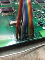
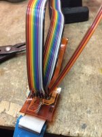

Summer is finally here, so ferrix has had some time to work on the portable.
You'll find the pictures of the cable he made attached to this post.
However, we still have two major problems here:
- When the display is plugged in, the system doesn't even attempt to boot - we think there might be a short somewhere that we still haven't figured out, because current consumption goes up to 3A and triggers the CC led in the power supply.
- When the display is disconnected, the system actually attempts to boot: we can hear it chime successfully most of the times, but as soon as it chimes the current level drops and the system shuts down. However, this is not happening predictably: if we only leave the yellow cable (pic below) connected the system tries to boot, chimes and shuts down. If we also connect the red cable, current goes instantly to zero and the system dies - if it's chiming, that produces a sad mac chime.
As always, we really appreciate your suggestions - we're not really experienced with portables, so any thought on this will be great!
Tried to edit, but timed out - actually connecting the red cable just makes the mac die instantly with no particular sign. The sad mac is happening more in a casual way - most of the times the yellow cable brings to a nice and reassuring chime, but sometimes (just sometimes, there doesn't seem to be any correlation) it goes to sad mac chime in the process.
Any thoughts? Could it be a problem with current or voltage regulation? Something drawing too much power? Something else?
Any thoughts? Could it be a problem with current or voltage regulation? Something drawing too much power? Something else?
shorted SWIM IC. Replace it. if you get current crowbarring without the display, this IC is bad.
Pull it and check other surrounding ICs for overheating signs using the finger test. sometimes when the SWIM goes, it knocks out a number of them. including the group of them between the CPU and the GPU, and sometimes one of the buffer IC goes in the RAM section just above the -5V regulator.
If you get current/short issues with the display connected, you likely have the cable wired wrong, or the display itself is shorted, or more likely, the inverter itself.
The symptoms you describe with random power-offs after startup, is cap goo current leakage between vias near the comparator IC to the right of the two reset/NMI buttons.
Its rare, but sometimes if the cap goo was bad enough, it will leak through the inner layers of the board and cause issues like this. The only solution is to locate arbitrary resistances in the PCB that arnt normal, and bypass that by cutting/rerunning traces. Only fix....
Pull it and check other surrounding ICs for overheating signs using the finger test. sometimes when the SWIM goes, it knocks out a number of them. including the group of them between the CPU and the GPU, and sometimes one of the buffer IC goes in the RAM section just above the -5V regulator.
If you get current/short issues with the display connected, you likely have the cable wired wrong, or the display itself is shorted, or more likely, the inverter itself.
The symptoms you describe with random power-offs after startup, is cap goo current leakage between vias near the comparator IC to the right of the two reset/NMI buttons.
Its rare, but sometimes if the cap goo was bad enough, it will leak through the inner layers of the board and cause issues like this. The only solution is to locate arbitrary resistances in the PCB that arnt normal, and bypass that by cutting/rerunning traces. Only fix....
Thanks tech!
I'm not really sure about the SWIM chip, though, so I'm asking you a couple more questions: when you're talking about crowbar activation, what do you mean exactly?
What we're seeing here is this: when we turn on the portable and the video cable is disconnected, we almost always hear a good starting chime (a couple of times we obtained a death chime at a certain point for unknown reason). Current measurement seems "normal" at this point. There seems to be some noise coming from the floppy as if it was looking for a track, you know, the normal noise you hear from a good floppy drive every time you turn on a classic mac with no disk inserted and that happens even before the chime.
After the chime is completed, current level drops to 0A and the system shuts down.
When the display cable is connected instead, we hear a different kind of noise, which sounds more electrical (could this be the crowbar activation?), and we never hear the chime. Also with the display connected we observed a couple of times the CC light on the test power supply that we're using - that power supply is tolerant up to 3A, so there must be a short somewhere here.
Given this, how much is it likely that the SWIM chip is involved? I'm very very ignorant about this, but it would seem to me that if such chip is dead, we should never hear a good chime coming from the machine. I'm referring to your topic here about the issue, but it seems a different behavior. However you're the master about portable issues, so I'm totally dependent on your judgement on this!
We're going to see if there are broken traces or cap goo in the area nearby the reset buttons you mentioned.
I'm not really sure about the SWIM chip, though, so I'm asking you a couple more questions: when you're talking about crowbar activation, what do you mean exactly?
What we're seeing here is this: when we turn on the portable and the video cable is disconnected, we almost always hear a good starting chime (a couple of times we obtained a death chime at a certain point for unknown reason). Current measurement seems "normal" at this point. There seems to be some noise coming from the floppy as if it was looking for a track, you know, the normal noise you hear from a good floppy drive every time you turn on a classic mac with no disk inserted and that happens even before the chime.
After the chime is completed, current level drops to 0A and the system shuts down.
When the display cable is connected instead, we hear a different kind of noise, which sounds more electrical (could this be the crowbar activation?), and we never hear the chime. Also with the display connected we observed a couple of times the CC light on the test power supply that we're using - that power supply is tolerant up to 3A, so there must be a short somewhere here.
Given this, how much is it likely that the SWIM chip is involved? I'm very very ignorant about this, but it would seem to me that if such chip is dead, we should never hear a good chime coming from the machine. I'm referring to your topic here about the issue, but it seems a different behavior. However you're the master about portable issues, so I'm totally dependent on your judgement on this!
We're going to see if there are broken traces or cap goo in the area nearby the reset buttons you mentioned.
I don't have a heat pencil, so it's quite hard to remove SMD chips with just a soldering iron.
At this point I am thinking about getting a regular video cable (If it is possible to obtain one) and making the inverter cable, since they have nothing in common.
Because the system powers on completely only for a couple of seconds (and then it powers down again), it's quite hard to check if a chip is bad.
I kept powering on, unplugging the power cable, plugging it back and powering on again for 5 minutes , then I took a thermal picture using my Flir One thermal camera:
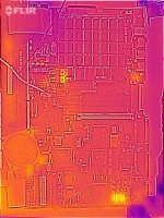
The only components that got slightly hotter than the rest are a those three TO220s and the sound chips.
The temperature range shown in the picture is from 23.7 °C to 32.0 °C.
The setup was very straightforward:
(in this picture the keyboard was moved to the other connector just for convenience. it doesn't matter where i plug it in)
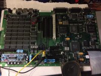
no cards connected, just power, keyboard and speakers. The problem is still the same. sometimes it chimes, and the a couple of seconds later it turns off. doesn't matter if you press one of the keys again or if you press the restart/NMI switches, it stays off. You have to unplug the power and then plug it back in.
this works if you only give power to one side of the connector (ground seems to be in common), if you apply power to both or only to the other one, the system will show no signs of life.
is it possible to have a simple pinout of that connector? when i connect the plug from the case (the one that goes to the main battery and to the 9V one) the voltage on both red cables is the same: 6.5V when the safety switch is pressed and 9V when is depressed (while using a 9V battery and mu bench power supply hooked up to the main battery terminals
The problem lies in the display cable, I haven't made the inverter cable yet.
At this point I am thinking about getting a regular video cable (If it is possible to obtain one) and making the inverter cable, since they have nothing in common.
Because the system powers on completely only for a couple of seconds (and then it powers down again), it's quite hard to check if a chip is bad.
I kept powering on, unplugging the power cable, plugging it back and powering on again for 5 minutes , then I took a thermal picture using my Flir One thermal camera:
The only components that got slightly hotter than the rest are a those three TO220s and the sound chips.
The temperature range shown in the picture is from 23.7 °C to 32.0 °C.
The setup was very straightforward:
(in this picture the keyboard was moved to the other connector just for convenience. it doesn't matter where i plug it in)
no cards connected, just power, keyboard and speakers. The problem is still the same. sometimes it chimes, and the a couple of seconds later it turns off. doesn't matter if you press one of the keys again or if you press the restart/NMI switches, it stays off. You have to unplug the power and then plug it back in.
this works if you only give power to one side of the connector (ground seems to be in common), if you apply power to both or only to the other one, the system will show no signs of life.
is it possible to have a simple pinout of that connector? when i connect the plug from the case (the one that goes to the main battery and to the 9V one) the voltage on both red cables is the same: 6.5V when the safety switch is pressed and 9V when is depressed (while using a 9V battery and mu bench power supply hooked up to the main battery terminals
Hi Ferrix97,
I'm not sure why I've never noticed this thread but I have an upgraded 5120 non-backlit to backlit upgrade and a working cable. Is there some way I can help? Maybe a picture or some continuity testing? I had some pictures up here once with the cable and card. I'll see if I can find them.
Found the thread but the pictures are gone unfortunately. Is there a way to get them back?
https://68kmla.org/forums/index.php?/topic/21333-macintosh-portable-5120-with-backlight-upgrade/?hl=5120
I'm not sure why I've never noticed this thread but I have an upgraded 5120 non-backlit to backlit upgrade and a working cable. Is there some way I can help? Maybe a picture or some continuity testing? I had some pictures up here once with the cable and card. I'll see if I can find them.
Found the thread but the pictures are gone unfortunately. Is there a way to get them back?
https://68kmla.org/forums/index.php?/topic/21333-macintosh-portable-5120-with-backlight-upgrade/?hl=5120
That is great!, thanks!
the best thing you could do is to make a table showing which pin of the Logic board adapter plug (the blue bit that goes from the white flat cable to the orange cable, first pic below) goes to which pin of the display (second pic below, the empty CN1).
before making the replacement cable, I took a photo of that plug and tired to match each of the "joints" with the corresponding number on the display (i wrote them on the silver solder joints). I think I did a mistake somewhere, but without a working cable I'm stuck.
right now I only need the video data, backlight should be easier.
essentially a table showing the connection from here
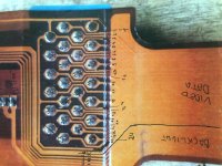
to here, CN1
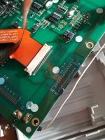
the best thing you could do is to make a table showing which pin of the Logic board adapter plug (the blue bit that goes from the white flat cable to the orange cable, first pic below) goes to which pin of the display (second pic below, the empty CN1).
before making the replacement cable, I took a photo of that plug and tired to match each of the "joints" with the corresponding number on the display (i wrote them on the silver solder joints). I think I did a mistake somewhere, but without a working cable I'm stuck.
right now I only need the video data, backlight should be easier.
essentially a table showing the connection from here
to here, CN1
Will do but I may not be able to get to it until Sunday at the latest. Are you sure CN1 lines up with the white flat ribbon connector on picture 2? From what can be seen in that picture, it doesn't look like it but it is hard to tell from the picture. Did you try to mark the pins in pic1 to the white connector in pic 2 first?
Great, thanks!
the connections between the flat cable connector and CN1 do match, the numbering is the same,
because CN1 is designed for another type of cable (flat ribbon), it has the even numbered pins on one side and the odd numbered pins on the other. the first and last two numbers are written on the silkscreen of the PCB
If i remember correctly, there were two o three pins that didn't go anywhere, on both connector. there wasn't continuity between the two pins on the two connectors
the connections between the flat cable connector and CN1 do match, the numbering is the same,
because CN1 is designed for another type of cable (flat ribbon), it has the even numbered pins on one side and the odd numbered pins on the other. the first and last two numbers are written on the silkscreen of the PCB
If i remember correctly, there were two o three pins that didn't go anywhere, on both connector. there wasn't continuity between the two pins on the two connectors
Okay, here's some pics. If you need a more detailed pic, let me know and good luck!
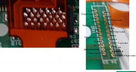
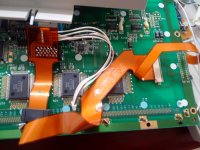
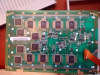
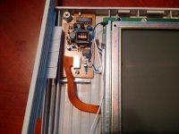
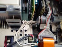
This is what you'll get when you fix it so don't give up!
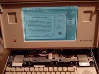
This is what you'll get when you fix it so don't give up!
Just saw the video. I'm not sure you're waiting long enough for it to actually start up. I haven't done any timing but it seem to take a good 30 seconds for things to come to life and I'm not sure if you hooked up the backlight but it doesn't come on when the screen goes black on start up. It doesn't turn on until almost partial boot up. I would say it take 5 or 10 seconds just to hear the hard drive come on.
Are you hearing this, at all? It does look like normal start up until you remove power.
When you get the start up beep, wait at least 30 seconds. Mine looks dead until it springs to life and the backlight is not on until then.
There's also a creaking sound, what is that?
Edit: for clarity, I mean "comes to life" AFTER the screen goes black and clears. It's an old computer and it needs a little extra time to get moving
Are you hearing this, at all? It does look like normal start up until you remove power.
When you get the start up beep, wait at least 30 seconds. Mine looks dead until it springs to life and the backlight is not on until then.
There's also a creaking sound, what is that?
Edit: for clarity, I mean "comes to life" AFTER the screen goes black and clears. It's an old computer and it needs a little extra time to get moving
the creaking sound was produced only after the sad mac. i don't know why.
currently the backlight is non connected, I haven't made the cable yet (a I guess I'll need you help for that)
right now I have no drives connected to it. after the screen clears, the current drops from 0.6A to 0.1A, which seems a bit low.
I left it there for a couple of minutes, nothing...
EDIT: after waiting, unplugging, rebooting... it finally decided to stay on the back screen after the chime. after a while the display started fading, so i hit the reset button and the display turned black again, current was hovering at about 0.8A.
at this point I heard a loud POP! coming from my instrument rack, maybe one of the capacitors inside my bench power supply decided to blow. I was recording a video when that happened. I may upload it later...
EDIT 2: whatever blew it was not involved in the portable setup, my power supply is fine (the filter cap is a bit dry, tho) and the portable seems to show the same problem, but now the black screen does not go away immeditely
currently the backlight is non connected, I haven't made the cable yet (a I guess I'll need you help for that)
right now I have no drives connected to it. after the screen clears, the current drops from 0.6A to 0.1A, which seems a bit low.
I left it there for a couple of minutes, nothing...
EDIT: after waiting, unplugging, rebooting... it finally decided to stay on the back screen after the chime. after a while the display started fading, so i hit the reset button and the display turned black again, current was hovering at about 0.8A.
at this point I heard a loud POP! coming from my instrument rack, maybe one of the capacitors inside my bench power supply decided to blow. I was recording a video when that happened. I may upload it later...
EDIT 2: whatever blew it was not involved in the portable setup, my power supply is fine (the filter cap is a bit dry, tho) and the portable seems to show the same problem, but now the black screen does not go away immeditely
I am going on the assumption that you would have previously fried something if there was a short in your Portable motherboard/display. Hopefully your bench power supply POP was a coincidence.
I am taking a guess at this but I could see the difference in amperage when the screen goes out because it's drawing no current and the the spike to 0.6A you are seeing is the display firing up and then going dim. I'm not sure if 0.1A is normal for just the motherboard. Someone else will have to chime in here.
Now that you have the cable properly doe, is there any difference if you disconnect it? If it's soldered, it will be hard to do but just checking.
I am taking a guess at this but I could see the difference in amperage when the screen goes out because it's drawing no current and the the spike to 0.6A you are seeing is the display firing up and then going dim. I'm not sure if 0.1A is normal for just the motherboard. Someone else will have to chime in here.
Now that you have the cable properly doe, is there any difference if you disconnect it? If it's soldered, it will be hard to do but just checking.
There is no difference in powering the system with or without the cable.
when the system is completely off, it draws almost next to nothing (like 0.02A), when i push both the reset and NMI buttons, it goes to 0.4A, when is showing something on the display is between 0.4 and 0.7A
EDIT: here is the video
when the system is completely off, it draws almost next to nothing (like 0.02A), when i push both the reset and NMI buttons, it goes to 0.4A, when is showing something on the display is between 0.4 and 0.7A
EDIT: here is the video
I can try to take a video at some point for reference. I don't have anything that can measure amperage, unfortunately, or that would have been useful as well. I have an ancient camcorder. Hopefully it can record straight to computer but I doubt it.
if you need to measure a limited amount of current, you can put a resistor in series with the load and measure the voltage across it, you can then get the current flowing thru the load by using the Ohm's law.
The hybrids go bad these units and will exert the same symptoms you see.
this is AFTER a recap BTW.
A quick fix is to put a 1 Meg ohm resistor between pins 18 and 16.
Also, there are pull-up resistors ,and 1 UF capacitors that attach to both the NMI and Reset buttons, if they go bad, or if there are broken traces there, the same thing will happen.
this is AFTER a recap BTW.
A quick fix is to put a 1 Meg ohm resistor between pins 18 and 16.
Also, there are pull-up resistors ,and 1 UF capacitors that attach to both the NMI and Reset buttons, if they go bad, or if there are broken traces there, the same thing will happen.
Thanks, once I get some free time I'll check the hybrid and the two caps.
Yes, the unit has been completely recapped
Yes, the unit has been completely recapped