

Thread
Another IIci ROM hack
DQ, how much did your ROM Programmer cost?
What's your target price for the Jolly Roger SIMM/four-at-a-time-ROM Programmer?
Tradeoffs: speed / convenience + board testing - cost = Grand Slam . . .
. . . any which way you cut it. :approve:
Don't lose sight of your design goals by looking back at what might or might not have been better or faster . . . it's WORKING! )
)
What's your target price for the Jolly Roger SIMM/four-at-a-time-ROM Programmer?
Tradeoffs: speed / convenience + board testing - cost = Grand Slam . . .
. . . any which way you cut it. :approve:
Don't lose sight of your design goals by looking back at what might or might not have been better or faster . . . it's WORKING!
)
Thanks guys! I agree, just the time savings from not having to screw around with the PLCC chips will be worth it.
Edit: Just tried, doesn't work You have to do a 3-byte sequence before every single byte written.
Some chips will let you completely enable/disable the software data protection whenever you want. With those chips, it would be possible to send a command to totally disable protection, then write tons of bytes, then re-enable the protection. On the chips I'm using, software data protection is always enabled. [Except on the smaller chips I was using, but the bigger chips are more useful for hackery]
Also, some chips, called page-write, will let you send an unlock command followed by a complete page (128 bytes, for example) of data quickly, just as fast as read cycles, into a page buffer. Then once you've finished sending the page (or smaller than a page), the actual write operation will happen which has a 5 microsecond (for example) delay. Unfortunately, the chips I'm using are not page-write chips [the smaller chips I was using are, though]
Edit: This may not work too well, actually -- the other chip I'm using has a worst case time of 300 microseconds per byte. It seems to get slower as it ages. I think I'm probably better off polling...
Edit 2: If not for that crazy 300 microsecond worst case time, this would actually help a ton. With an 18 us delay (because I know the initial SPI setup will take up the other 2 us), the programming takes 1 minute and 11 seconds. Maybe I should look into optimizing my SPI read/write functions as much as possible...
Because of the low PCB quantity, the PCB itself is one of the most expensive parts -- I'm talking $6 each when we factor in the shipping I paid. That will go down as I get a bigger order of them depending on how many people are interested. The rest of the parts total around $15 per unit and that could go down as I buy some of the more expensive parts (the ICs) in bigger quantities. Plus, assembly time is longer with these boards because it feels like there are a bazillion different values of resistors and capacitors that I have to keep organized and put in the right place on the PCB, so I hope everyone understands that I'm not just selling these for the price of the parts
I'm probably going to be looking at a price of around $35 plus shipping for the board, and the SIMMs will still be $16 for the SIMM, +$4 for the set of 4 chips = $20 (thanks to trag, I have been able to lower the price of the ROM chips)
Edit again: At this level, every little optimization counts. Setting two flags with one instruction rather than one flag at a time means a difference of 15 seconds in programming time. Maybe I can write my SPI routine in assembly ;-)
This is a thing that is different for every chip -- I've been doing a lot of looking at Flash memory datasheets to try to understand how the commands work. The chips that I'm using only have a byte program mode. The datasheet claims that once the single byte write operation has completed, the chip will go back into read mode. I haven't tried writing another byte without the unlock sequence, but I suspect it will fail. I'll try it just to be sure, though.
Edit: Just tried, doesn't work
You have to do a 3-byte sequence before every single byte written. Some chips will let you completely enable/disable the software data protection whenever you want. With those chips, it would be possible to send a command to totally disable protection, then write tons of bytes, then re-enable the protection. On the chips I'm using, software data protection is always enabled. [Except on the smaller chips I was using, but the bigger chips are more useful for hackery]
Also, some chips, called page-write, will let you send an unlock command followed by a complete page (128 bytes, for example) of data quickly, just as fast as read cycles, into a page buffer. Then once you've finished sending the page (or smaller than a page), the actual write operation will happen which has a 5 microsecond (for example) delay. Unfortunately, the chips I'm using are not page-write chips [the smaller chips I was using are, though]
That's true -- the worst case time, they claim, is 20 microseconds, with a typical time of 14 microseconds. I'm thinking because of the length of that time, I may not be losing much from polling anyway. I will go ahead and try it though, to see what kind of performance I get. Good idea!
Edit: This may not work too well, actually -- the other chip I'm using has a worst case time of 300 microseconds per byte. It seems to get slower as it ages. I think I'm probably better off polling...
Edit 2: If not for that crazy 300 microsecond worst case time, this would actually help a ton. With an 18 us delay (because I know the initial SPI setup will take up the other 2 us), the programming takes 1 minute and 11 seconds. Maybe I should look into optimizing my SPI read/write functions as much as possible...
The programmer I'm using was like $60...
Because of the low PCB quantity, the PCB itself is one of the most expensive parts -- I'm talking $6 each when we factor in the shipping I paid. That will go down as I get a bigger order of them depending on how many people are interested. The rest of the parts total around $15 per unit and that could go down as I buy some of the more expensive parts (the ICs) in bigger quantities. Plus, assembly time is longer with these boards because it feels like there are a bazillion different values of resistors and capacitors that I have to keep organized and put in the right place on the PCB, so I hope everyone understands that I'm not just selling these for the price of the parts
I'm probably going to be looking at a price of around $35 plus shipping for the board, and the SIMMs will still be $16 for the SIMM, +$4 for the set of 4 chips = $20 (thanks to trag, I have been able to lower the price of the ROM chips)
Edit again: At this level, every little optimization counts. Setting two flags with one instruction rather than one flag at a time means a difference of 15 seconds in programming time. Maybe I can write my SPI routine in assembly ;-)
I don't know what I've done to my board, but something is wrong with it now. It's crashing all the time and acting up, even with older versions of my program that used to work fine :-( I don't know exactly what's causing it, but especially when I do stuff that involves write cycles, I hear the "USB unplug" sound that Windows plays -- it's like the device is getting unplugged and plugged back in. After I did some improvements to my polling algorithm, everything went haywire and quit working so I figured it was a bug in my algorithm, but now I realize it's not my algorithm because older versions of the program are messed up too.
Ugh! )($#)@(*$(*@#)#@ :disapprove:
Edit: And now with an old program back on it, it's working OK again...maybe that's a sign I should just take a break?
I can "hear" USB data on my headphones because my PC's case doesn't have very well-shielded cables for the headphone jack. It happens with most USB devices that do stuff at high speeds. One thing that worries me is that when I'm writing the chips with a repetitive set of data, I can hear a high-pitched noise on my headphones even though I'm not sending or receiving any USB data. Could my SPI be interfering with the USB data lines? Is there something I should be doing on the board to help with that?
Ugh! )($#)@(*$(*@#)#@ :disapprove:
Edit: And now with an old program back on it, it's working OK again...maybe that's a sign I should just take a break?
I can "hear" USB data on my headphones because my PC's case doesn't have very well-shielded cables for the headphone jack. It happens with most USB devices that do stuff at high speeds. One thing that worries me is that when I'm writing the chips with a repetitive set of data, I can hear a high-pitched noise on my headphones even though I'm not sending or receiving any USB data. Could my SPI be interfering with the USB data lines? Is there something I should be doing on the board to help with that?
It sounds almost like a low-power problem. Are you by chance using a different USB port than before, or have more USB devices attached to your computer? Does it happen if you remove the SIMM from the programmer?
Edit:
USB is pretty good with noise because it's twisted pair, like ethernet. There's a + line and a - line, and these are subtracted or something, which results in eliminating most outside noise. You could try a USB cable that has a ferrite bead in it. That takes out some high frequency noise.
Edit:
USB is pretty good with noise because it's twisted pair, like ethernet. There's a + line and a - line, and these are subtracted or something, which results in eliminating most outside noise. You could try a USB cable that has a ferrite bead in it. That takes out some high frequency noise.
Same port and no more devices attached than before. Unfortunately now I can't reproduce the problem and the new algorithm is working fine too (it's 5 seconds faster than the old one). This is so weird, but I do hear a high pitched buzzing on my headphones when the algorithm is in progress, despite the fact that nothing is being sent over USB.
Edit: At this point I don't know. I tried again with a ferrite bead USB cable and now I can't get the new algorithm to work. Actually, WTF? Depending on whether I use a shorter or longer cable, that makes a difference as to how well it works.
1) Short (3ft) non-ferrite-bead cable:
WITH SIMM:
New algorithm works. I can hear high pitched buzzing during write through my headphones.
No problems.
WITHOUT SIMM:
New algorithm works. No high pitched buzzing during write.
No problems.
2) Long (6ft) ferrite bead cable *and* Long (6ft) non-ferrite-bead cable:
WITH SIMM:
Doesn't work -- disconnect/reconnect problem as soon as I try to do a write/identification of the chips (although erase DOES work!)
WITHOUT SIMM:
New algorithm works. No high pitched buzzing during write.
With no SIMM in place, everything works OK no matter what. It's only when the SIMM is in place with a longer cable that the problem occurs. I have the device requesting 500 mA of current from USB, and the chips' current ratings don't even come close to 500 mA combined, even when writing. The AVR itself draws about 30 mA at max, the chips draw 35 mA at max each, and the GPIO expander draws 1 mA at 1 MHz (probably more since I'm running it at 8 MHz). What gives? I'm confused now...
Better sleep on it xx(
Edit: At this point I don't know. I tried again with a ferrite bead USB cable and now I can't get the new algorithm to work. Actually, WTF? Depending on whether I use a shorter or longer cable, that makes a difference as to how well it works.
1) Short (3ft) non-ferrite-bead cable:
WITH SIMM:
New algorithm works. I can hear high pitched buzzing during write through my headphones.
No problems.
WITHOUT SIMM:
New algorithm works. No high pitched buzzing during write.
No problems.
2) Long (6ft) ferrite bead cable *and* Long (6ft) non-ferrite-bead cable:
WITH SIMM:
Doesn't work -- disconnect/reconnect problem as soon as I try to do a write/identification of the chips (although erase DOES work!)
WITHOUT SIMM:
New algorithm works. No high pitched buzzing during write.
With no SIMM in place, everything works OK no matter what. It's only when the SIMM is in place with a longer cable that the problem occurs. I have the device requesting 500 mA of current from USB, and the chips' current ratings don't even come close to 500 mA combined, even when writing. The AVR itself draws about 30 mA at max, the chips draw 35 mA at max each, and the GPIO expander draws 1 mA at 1 MHz (probably more since I'm running it at 8 MHz). What gives? I'm confused now...
Better sleep on it xx(
I think I figured it out, it's the brownout detector built into the AVR. I had it set to 4.3 volts, but it appears the voltage is briefly dropping below 4.3 volts, causing the AVR to reset. The reason I say that is because when I changed the brown out detect level to 2.2 volts instead of 4.3 volts, the problem went away with my long ferrite bead cable.
I don't really feel comfortable with the voltage going that low when it's supposed to be between 4.5 to 5.5 volts on the chips. Do I need some capacitors or something to ensure I have at least 5 volts? The USB spec seems to say that I shouldn't have more than a 10 uF capacitor next to the USB port (which I have - 10 uF) -- would I need to put a bigger capacitor behind a transistor and only allow power to that part of the circuit after I'm all powered up or something? Any ideas?
The voltage my circuit is getting is 4.85 volts at idle, and it drops to about 4.8 when burning the chips, but there must be some kind of a quick dropout where it goes below 4.3 briefly -- wouldn't that point to needing a better capacitor somewhere to filter that out? I don't have a scope to try to see it.
I don't really feel comfortable with the voltage going that low when it's supposed to be between 4.5 to 5.5 volts on the chips. Do I need some capacitors or something to ensure I have at least 5 volts? The USB spec seems to say that I shouldn't have more than a 10 uF capacitor next to the USB port (which I have - 10 uF) -- would I need to put a bigger capacitor behind a transistor and only allow power to that part of the circuit after I'm all powered up or something? Any ideas?
The voltage my circuit is getting is 4.85 volts at idle, and it drops to about 4.8 when burning the chips, but there must be some kind of a quick dropout where it goes below 4.3 briefly -- wouldn't that point to needing a better capacitor somewhere to filter that out? I don't have a scope to try to see it.
If you don't already have one, try putting another small ceramic or tantalum capacitor as close to the VCC and GND pins of the atmega as you can get it. Something around 0.1 uF to 1 uF or so.
Maybe try using a low-ESR capacitor, although I'm not sure if that's important.
Maybe try putting a small ~22 uH inductor in series with the VCC line. Check out the section about hot insertion near the bottom of this page: http://elm-chan.org/docs/mmc/mmc_e.html
Maybe try using a low-ESR capacitor, although I'm not sure if that's important.
Maybe try putting a small ~22 uH inductor in series with the VCC line. Check out the section about hot insertion near the bottom of this page: http://elm-chan.org/docs/mmc/mmc_e.html
You're playing with fairly high frequencies on a bare board. Are you sure it's not just RFI?
I have small ceramic 0.1 uF capacitors (bypass capacitors?) next to each pair of GND/VCC pins on the AVR. Should I add extras to each one?
Thanks -- that will be fairly tough since I have VCC splitting off into multiple directions directly under the USB port. I may have to do some fixes to rev. 2 on this board
No clue -- how could I tell? I do know that turning off the brownout detector fixes it, so the voltage to the microcontroller is definitely dropping below 4.3 volts...
If you've already got capacitors at each PWR/GND pair, then I think you're covered from that standpoint.
Is there any chance you could borrow a scope to help diagnose it? Any hacker spaces near you that you could visit?
Or if it's consistently working OK with the brownout detection disabled, then just smile and move on.
Is there any chance you could borrow a scope to help diagnose it? Any hacker spaces near you that you could visit?
Or if it's consistently working OK with the brownout detection disabled, then just smile and move on.
Haha, ok, thanks
I'll take it to work at some point and look at it with a scope there.
I'll take it to work at some point and look at it with a scope there.
Welcome to circuit board hell. Been there, done that.
Your gonna need a good reserve cap on the USB port for saftey reasons, but try putting the board inside a "faraday cage" and see if it makes a difference. Scope the VCC line for glitches while trying to write or use the SIMM in any way.
Your gonna need a good reserve cap on the USB port for saftey reasons, but try putting the board inside a "faraday cage" and see if it makes a difference. Scope the VCC line for glitches while trying to write or use the SIMM in any way.
This is probably past relevance here, but:
Do you know WHY you’re supposed to use decoupling capacitors? (Hackaday)
Do you know WHY you’re supposed to use decoupling capacitors? (Hackaday)
AYUP! That'd be the test.

WAG: The problem may go away when you turn off the brownout detector, but that might only be reducing the strength or changing the frequency of the signal to the point that your headphone wires aren't acting as an antenna. IIRC, technight knows his way around when it comes to RFI and antenna lengths/wavelength multiples and a metric crapload of stuff I can barely grasp.
Another silly question: Are you hooked up to a powered hub or running straight off the PC's USB port?
The USB ports on the Mac's peripherals are, or were, notoriously underpowered, requiring the use of a powered hub for proper function.
Cool beans overall, DQ! :approve:
I just had a huge reply typed up to everyone and then Microsoft's *ridiculous* decision to make the backspace key go back in Internet Explorer when you aren't in a text field caused me to lose it all. Remind me why I'm not using a Mac right now? Seriously, who makes a UI decision like that? At the very least it shouldn't forget what you had typed in the box if you click forward to return to where you were before. [Looks like Google.com intercepts it, but most other websites don't...and shouldn't need to...] Anyway, that's enough of that rant...
It's not fun at all!
I'll try the faraday cage and scope stuff. Can I just put it inside a closed metal box of some kind?
That's the plan, for sure.
Here's the deal -- all higher-speed USB devices cause weird sounds on my PC's front headphone jack when they are plugged into the front USB ports (that's what I'm doing). My iPhone does it, external hard drives do it, external USB jump drives do it. My SIMM programmer does *not* do it -- until I start writing to the SIMM. But I'm not transferring any data over USB while I'm programming yet -- it's just writing the same repetitive pattern to the chips. So it's like the USB lines are picking up noise from my board when it's writing to the SIMM (maybe from the SPI communication to the GPIO expander chip?)
I'll try it and post back later. I am currently plugging it into one of my PC's front USB ports. I should also try the rear USB ports and see if there's a difference. I should also try it on different computers [MacBook Pro, older Macs, other PCs] and look for a difference there, and measure the voltage and all that too.
Lots of tests to try....thanks for the ideas everyone!
Seriously, who makes a UI decision like that? At the very least it shouldn't forget what you had typed in the box if you click forward to return to where you were before. [Looks like Google.com intercepts it, but most other websites don't...and shouldn't need to...] Anyway, that's enough of that rant... It's not fun at all!How can I get away with putting more than 10uF of capacitance on the USB +5V? I have a 10 uF, 10 V max ceramic capacitor (yes, ceramic and that big) right next to the USB port on the bottom of the board. The USB spec says no more than that because of too much inrush current, and people have said online that putting more than that causes problems with the device working with some computers. I saw online somewhere that you can put more stuff behind a MOSFET and use a resistor to the control line for the MOSFET (I can't remember which lines are named what on MOSFETs, sorry!) to make it slowly come up...does that sound reasonable? I'll find a link later...
I'll try the faraday cage and scope stuff. Can I just put it inside a closed metal box of some kind?
Thanks! Lots of good stuff in that and the following discussion
Agreed that I should find out what the actual root cause is rather than just turn off the brownout detector
That's the plan, for sure.Here's the deal -- all higher-speed USB devices cause weird sounds on my PC's front headphone jack when they are plugged into the front USB ports (that's what I'm doing). My iPhone does it, external hard drives do it, external USB jump drives do it. My SIMM programmer does *not* do it -- until I start writing to the SIMM. But I'm not transferring any data over USB while I'm programming yet -- it's just writing the same repetitive pattern to the chips. So it's like the USB lines are picking up noise from my board when it's writing to the SIMM (maybe from the SPI communication to the GPIO expander chip?)
That's definitely not a silly question -- it's a good idea
I'll try it and post back later. I am currently plugging it into one of my PC's front USB ports. I should also try the rear USB ports and see if there's a difference. I should also try it on different computers [MacBook Pro, older Macs, other PCs] and look for a difference there, and measure the voltage and all that too.Lots of tests to try....thanks for the ideas everyone!
Doh! You're definitely facing some circuit board voodoo, and scope measurements are probably the best thing to help diagnose it further. But taking my best guess based on what you've described, this sounds like a voltage sag problem to me, and not RFI. It's quite likely that those EEPROM chips suck down a fair amount of current when you perform a write to them. If that's the case, here a few other things you could check:
Do all the EEPROM chips have decoupling capacitors too?
Is the 10uF capacitor pretty close (in terms of trace length) to the AVR and the EEPROM chips?
Your board doesn't have a voltage regulator, does it? I think it wouldn't need one, but if it does, what's its current rating?
As a test, could you try modifying your code to program the ROMs in round-robin fashion, instead of all at the same time, and see if the brownout detector still kicks in? Or insert a short delay after each byte programmed?
EDIT: 28. 8-o
Do all the EEPROM chips have decoupling capacitors too?
Is the 10uF capacitor pretty close (in terms of trace length) to the AVR and the EEPROM chips?
Your board doesn't have a voltage regulator, does it? I think it wouldn't need one, but if it does, what's its current rating?
As a test, could you try modifying your code to program the ROMs in round-robin fashion, instead of all at the same time, and see if the brownout detector still kicks in? Or insert a short delay after each byte programmed?
EDIT: 28. 8-o
I can't program to each chip individually - it's all or none. Well, unless I screw up the unlock sequence on the other chips. But it's not just writing that screws it up -- trying to read the manufacturer/product ID from the chips causes it too. I can, however, pull out some of the chips. In fact, I did that the other day and it made the problem go away, if I remember right. I'll have to play with delays and removing chips.
All the Flash chips have decoupling capacitors on the SIMM. The 10 uF capacitor is really close to the USB port and not too far from the AVR itself. No voltage regulator -- just takes the +5V directly from the USB port. A picture is worth a million words, so here's what I have:
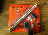
The decoupling caps are circled in green and are 0.1uF. (the capacitor near the USB port in the pic above is not a decoupling cap -- it's a 1uF cap for the USB (3.3V?) regulator built into the AVR connected to the UCAP pin)
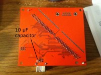
The cap in the pic above is the 10 uF capacitor I've been talking about.
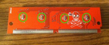
Here are the decoupling caps on the SIMM for the flash chips. The PLCC sockets are on the other side.
All the Flash chips have decoupling capacitors on the SIMM. The 10 uF capacitor is really close to the USB port and not too far from the AVR itself. No voltage regulator -- just takes the +5V directly from the USB port. A picture is worth a million words, so here's what I have:
The decoupling caps are circled in green and are 0.1uF. (the capacitor near the USB port in the pic above is not a decoupling cap -- it's a 1uF cap for the USB (3.3V?) regulator built into the AVR connected to the UCAP pin)
The cap in the pic above is the 10 uF capacitor I've been talking about.
Here are the decoupling caps on the SIMM for the flash chips. The PLCC sockets are on the other side.
Hmm It seems that you have plenty of caps where you need them. Here's a thought.
Your SPI I/O expanders are bi-directional and you switch direction for reading and writing data to/from the ROM chips, is this correct? And then you do some corresponding direction change to the ROMs too? Well, maybe there are delays involved in switching direction beyond what you had considered, and at some point in the process, the ROMs and I/O expanders end up being outputs at the same time for a moment. This could basically be a short circuit, which could defeat your caps.
Some chips offer a quasi-bi-directional option, that's a weaker output that can be safely driven high or low. You could check to see if you have that option anywhere and use it instead of output direction to see if the problem disappears.
Your SPI I/O expanders are bi-directional and you switch direction for reading and writing data to/from the ROM chips, is this correct? And then you do some corresponding direction change to the ROMs too? Well, maybe there are delays involved in switching direction beyond what you had considered, and at some point in the process, the ROMs and I/O expanders end up being outputs at the same time for a moment. This could basically be a short circuit, which could defeat your caps.
Some chips offer a quasi-bi-directional option, that's a weaker output that can be safely driven high or low. You could check to see if you have that option anywhere and use it instead of output direction to see if the problem disappears.
Whoa ---- Dennis Nedry, I think you nailed it!!! You are a genius!
I forgot that I had been playing around with some of my read/write cycle routines around the time this problem happened -- I had done a bunch of manipulation of the control lines in my bigger routines for writing to and identifying the chip, but then I realized I was repeating a bunch of code so I made a ReadCycle() and WriteCycle() routine. In the process of converting my code, I got the ordering of some of the operations mixed up (I had it correct before that change).
I just looked at my code:
See anything wrong with this? I'm asserting CS and OE, which will cause the Flash chips to output data on the data lines, and *then* setting the data pins as inputs on the microcontroller and SPI. If this function is called after a write cycle, the data lines on the microcontroller and SPI expander chip will already be outputs because that's how they were left by the write cycle routine, so the AVR's 16 data pins, the SPI expander's 16 data pins, and the flash chips' 32 data pins will all be outputs momentarily until I can get the SPI command to the expander chips to tell them to become inputs (and then I change the microcontroller's 16 pins to inputs directly after that). That's a relatively long time because of the serial communications!
The correct code is:
Which ensures that the data lines are set as inputs on the microcontroller and SPI expander before allowing the flash chips to output any data. I made that change, and no more brownouts at 4.3V! It was a SOFTWARE bug all along!
THANK YOU THANK YOU THANK YOU, Dennis Nedry! That was the problem. I'm still going to look at it on a scope to see what everything looks like, though With AND without the bug so I can see what was going on!
I forgot that I had been playing around with some of my read/write cycle routines around the time this problem happened -- I had done a bunch of manipulation of the control lines in my bigger routines for writing to and identifying the chip, but then I realized I was repeating a bunch of code so I made a ReadCycle() and WriteCycle() routine. In the process of converting my code, I got the ordering of some of the operations mixed up (I had it correct before that change).
I just looked at my code:
Code:
uint32_t ExternalMem_ReadCycle(uint32_t address)
{
ExternalMem_Deassert(SIMM_WE);
ExternalMem_Assert(SIMM_CS | SIMM_OE);
ExternalMem_SetDataAsInput();
ExternalMem_SetAddress(address);
uint32_t tmp = ExternalMem_ReadData();
ExternalMem_Deassert(SIMM_OE);
return tmp;
}The correct code is:
Code:
uint32_t ExternalMem_ReadCycle(uint32_t address)
{
ExternalMem_Deassert(SIMM_WE);
ExternalMem_SetDataAsInput();
ExternalMem_Assert(SIMM_CS | SIMM_OE);
ExternalMem_SetAddress(address);
uint32_t tmp = ExternalMem_ReadData();
ExternalMem_Deassert(SIMM_OE);
return tmp;
}THANK YOU THANK YOU THANK YOU, Dennis Nedry! That was the problem. I'm still going to look at it on a scope to see what everything looks like, though
With AND without the bug so I can see what was going on!dougg3,
are you sure it is 10uF (microfarad) and not 10nF (0..01uF = 10 nanofarad) cap? I've never seen ceramic capacitor of 10uF of that small size.
EDIT - if it is indeed 10uF, do you have the data sheet? I am curious which manufacturer managed to squeeze 10uF in that package.
My boss said the same thing when I showed him, but I'm pretty sure it's 10 uF. It's a bit taller than the other 0805 capacitors I use on the board:
http://parts.digikey.com/1/parts/1707835-cap-ceramic-10uf-10v-y5v-0805-cc0805zky5v6bb106.html
I just noticed the tolerance on it kind of sucks (-20% to +80% -- that's bad, right?), so I might be better off switching to a bigger size in my next revision...
Here's the datasheet:
http://media.digikey.com/pdf/Data%20Sheets/Yageo%20PDFs/MLCC%20ordering%20code.pdf
EDIT: No, that was crap. Here's the datasheet:
http://www.yageo.com/documents/recent/UPY-GPHC_Y5V_6.3V-to-50V_5.pdf
CC0805ZKY5V6BB106 decodes to:
MLCC, 0805 size, -20%/+80% tolerance, 7" plastic packing, Y5V code, 10V, Ni-Barrier, Base Metal Electrodes, and I guess the spec sheet doesn't say what 106 means, but it's fairly obvious what it means since 104 = 0.1uF and 105 = 1 uF
http://parts.digikey.com/1/parts/1707835-cap-ceramic-10uf-10v-y5v-0805-cc0805zky5v6bb106.html
I just noticed the tolerance on it kind of sucks (-20% to +80% -- that's bad, right?), so I might be better off switching to a bigger size in my next revision...
Here's the datasheet:
http://media.digikey.com/pdf/Data%20Sheets/Yageo%20PDFs/MLCC%20ordering%20code.pdf
EDIT: No, that was crap. Here's the datasheet:
http://www.yageo.com/documents/recent/UPY-GPHC_Y5V_6.3V-to-50V_5.pdf
CC0805ZKY5V6BB106 decodes to:
MLCC, 0805 size, -20%/+80% tolerance, 7" plastic packing, Y5V code, 10V, Ni-Barrier, Base Metal Electrodes, and I guess the spec sheet doesn't say what 106 means, but it's fairly obvious what it means since 104 = 0.1uF and 105 = 1 uF
Hmmm, indeed, 10uF...
http://www.johansondielectrics.com/technical-notes/product-training/basics-of-ceramic-chip-capacitors.html
Try to solder some regular radial 10uF paralel to your ceramic cap and see what happens.
Not necesserily. It's theY5V material that's not so stellar.
http://www.johansondielectrics.com/technical-notes/product-training/basics-of-ceramic-chip-capacitors.html
Try to solder some regular radial 10uF paralel to your ceramic cap and see what happens.
OK -- I'll play with that when I'm around a scope to see what kind of difference it makes It will be interesting to see if my bad code works better if I have a larger 10 uF electrolytic there instead.
If I stuck with the small ceramic, maybe something like this (X7R) would work better?
http://search.digikey.com/us/en/products/LMK212B7106KG-TD/587-2668-1-ND/2417255
Thanks for the link -- that's interesting that the lower quality ceramics will age over time but it's curable by heating them to 125 degrees Celsius. Looks like even the X7R would suffer from that phenomenon too. Maybe I should try to stick with NP0 for everything...
It will be interesting to see if my bad code works better if I have a larger 10 uF electrolytic there instead.If I stuck with the small ceramic, maybe something like this (X7R) would work better?
http://search.digikey.com/us/en/products/LMK212B7106KG-TD/587-2668-1-ND/2417255
Thanks for the link -- that's interesting that the lower quality ceramics will age over time but it's curable by heating them to 125 degrees Celsius. Looks like even the X7R would suffer from that phenomenon too. Maybe I should try to stick with NP0 for everything...
Yes, scope is your best friend.
Yes, they're better, but not cheap, as you can see. For $0.55 per unit one can get some pretty decent low esr electrolytic, I think.
That would be overkill for your project. X7R is standart for general purpose +Vcc decoupling these days, besides, NP0 caps will be much larger for given package sizeand I'm not sure one can get 10uF in NP0.
I don't understand a single that that went on, but... huzzah! :lol:THANK YOU THANK YOU THANK YOU, Dennis Nedry! That was the problem. I'm still going to look at it on a scope to see what everything looks like, though
i know exactly what your saying doug3. propogation delay can be your worst enemy in those cases. if your switch your inputs and outputs around, any bit of propogation delay at all could result in an output driving an output condition creating a "glitch". its known as shootthrough if i remember correctly.
shootthrough is especially important if your building a motor driver or switching power supply circuit. both top and bottom transistors cannot be on at the same time. In your case, the shootthrough wasnt caused by the same circuit, it was caused by a low-side driver being turned on at the same time a high side driver was turned on in a separate, but connected circuit as both circuits were set as output at that point in time. Causes shoothrough. Even though this timeframe could only be 100nanoseconds before one side of the circuit finally switches to an input, still 100nanoseconds is 100nanoseconds that they both remain outputs, which is 100nanoseconds of a possible shootthrough event.
shootthrough is especially important if your building a motor driver or switching power supply circuit. both top and bottom transistors cannot be on at the same time. In your case, the shootthrough wasnt caused by the same circuit, it was caused by a low-side driver being turned on at the same time a high side driver was turned on in a separate, but connected circuit as both circuits were set as output at that point in time. Causes shoothrough. Even though this timeframe could only be 100nanoseconds before one side of the circuit finally switches to an input, still 100nanoseconds is 100nanoseconds that they both remain outputs, which is 100nanoseconds of a possible shootthrough event.
Ah, ok! Well, in this case, it was in the range of more than 4 microseconds because of the time it takes to finish sending the serial commands to the expander chip. I had to send 4 bytes to the SPI chip at 8 MHz, plus I had to modify two 8-bit registers in the microcontroller. 4 bytes [32 bits] at 8 MHz is 4 microseconds, and then writing the registers to change the other two...so it was a very significant amount of time
I'll chalk it up to coding too late at night |)
I am really curious to try doing it as a parallel bus in a future revision (much later down the road, don't worry!) and ditch the SPI. I'm happy with the SPI but I think there are possibilities for future major speed increases, even if I do lose some electrical testing capabilities. I know everyone says I shouldn't go crazy over-engineering it, but I really do think it would be fun just as a learning experience I could keep an older board revision for testing SIMMs, but this newer revision would be great for raw performance. I know there's some combination of latches or something like that that could do it easily, allowing me to share my 16 data lines as a single 32-bit data bus.
I'll chalk it up to coding too late at night |)
I am really curious to try doing it as a parallel bus in a future revision (much later down the road, don't worry!) and ditch the SPI. I'm happy with the SPI but I think there are possibilities for future major speed increases, even if I do lose some electrical testing capabilities. I know everyone says I shouldn't go crazy over-engineering it, but I really do think it would be fun just as a learning experience
I could keep an older board revision for testing SIMMs, but this newer revision would be great for raw performance. I know there's some combination of latches or something like that that could do it easily, allowing me to share my 16 data lines as a single 32-bit data bus.
who cares if you over-engineer it? its your masterpeice, and as long as it works all is dandy
I over-engineer things all the time. For example, an MP3 player that has 2 CPUs, a VFD display, and high voltage boost converters/anode drivers. Talk about over-engineering, but hey its fun.
I also under-engineer things, like building an entire full size electronic outdoor scoreboard using sheet metal and vinyl covered pegboard, also without using a single capacitor. and it WORKED. lol.
I over-engineer things all the time. For example, an MP3 player that has 2 CPUs, a VFD display, and high voltage boost converters/anode drivers. Talk about over-engineering, but hey its fun.
I also under-engineer things, like building an entire full size electronic outdoor scoreboard using sheet metal and vinyl covered pegboard, also without using a single capacitor. and it WORKED. lol.
I "overengineered" the sign structures we built for almost 30 years. The only time one "failed" was during a hurricane, the center joint sections of the sandwich structure the sign riggers didn't tie together gave way. Luckily the single one of the four 5' x 16' panels that flew loose didn't even hit anything . . .
. . . but we bought our own crane truck after that. [}] ]'>
Moral of story:
Murphy is alive and well and lurking around every corner, do what you need to do to keep him napping, but don't worry so much about speed. This is a hobbyist project tool, the important part is that it works, makes the SIMMs more reliable over time, simplifies their build/testing processes and saves time overall in programming all four ROMs in situ . . . and has an expansion slot for additional ROM tomfoolery, so speed isn't even a serious consideration . . .
. . . anything under five minutes is friggin' gravy! Whatcha' want, DQ? Egg in your beer? [] ]'>
Go Dawg, GO!)
. . . but we bought our own crane truck after that. [}
] ]'>Moral of story:
Murphy is alive and well and lurking around every corner, do what you need to do to keep him napping, but don't worry so much about speed. This is a hobbyist project tool, the important part is that it works, makes the SIMMs more reliable over time, simplifies their build/testing processes and saves time overall in programming all four ROMs in situ . . . and has an expansion slot for additional ROM tomfoolery, so speed isn't even a serious consideration . . .
. . . anything under five minutes is friggin' gravy! Whatcha' want, DQ? Egg in your beer? [
] ]'>Go Dawg, GO!
)
All right...I have something working! Writing the code (basically a big state machine) for the communication protocol on both ends is so boring...it's not difficult at all, just tedious.
I don't have any verification going on yet. The protocol is basically this: my GUI app asks the programmer if it can program, gets an OK response, then it sends 1 KB. Next it waits to hear a reply from the programmer on how that went, and repeats that process until it's done writing the data. I had to break it down into something about that size because the AVR only has 4 KB of RAM
It takes just under 2 minutes to do a complete write that way. I'm thinking performance could be improved by allowing the next 1 KB chunk to be sent while the first one is still being written to the SIMM, but at this point I just want to get the entire feature set up and running.
Anyway, I wrote my long Mario startup chime to a SIMM, stuck it in there...and it didn't work at first. Turns out I had the order of the chips reversed in my code. ;-) I think I got confused because the 68030 is big-endian and the code generated for the AVR is little-endian. (I don't think the AVR has an endianness because it's 8-bit, but the compiler does everything as little-endian). After fixing that, it works great!
I don't have any verification going on yet. The protocol is basically this: my GUI app asks the programmer if it can program, gets an OK response, then it sends 1 KB. Next it waits to hear a reply from the programmer on how that went, and repeats that process until it's done writing the data. I had to break it down into something about that size because the AVR only has 4 KB of RAM
It takes just under 2 minutes to do a complete write that way. I'm thinking performance could be improved by allowing the next 1 KB chunk to be sent while the first one is still being written to the SIMM, but at this point I just want to get the entire feature set up and running.
Anyway, I wrote my long Mario startup chime to a SIMM, stuck it in there...and it didn't work at first. Turns out I had the order of the chips reversed in my code. ;-) I think I got confused because the 68030 is big-endian and the code generated for the AVR is little-endian. (I don't think the AVR has an endianness because it's 8-bit, but the compiler does everything as little-endian). After fixing that, it works great!