

Thread
VACUUM FORMING ACRYLIC: First failed . . .
. . . attempt made today. It was a half-@$$ed attempt, so I was unsurprised by the nasty results . . . but still . . . :-/
I built the frame, some spacers and a flange so I'd have flat surfaces to mate the face and tube halves of a fake 9" Compact CRT.
I was about half finished when I decided to try the heat gun method instead of building a frame for the oven heating method . . . no joy in Suckville. I did learn how to boil the surface of plexi to get some really interesting bubble effects though . . .
. . . but that probably won't be part of any finished project parts. :
I've been documenting the process, but I ain't sharin' until I finish the rest of the apparatus and have something just a bit less fugly to show for my efforts.
It's time to kick back and watch a mindless movie, all in all, it has been a fun day! [ ] ]'>
] ]'>
I built the frame, some spacers and a flange so I'd have flat surfaces to mate the face and tube halves of a fake 9" Compact CRT.
I was about half finished when I decided to try the heat gun method instead of building a frame for the oven heating method . . . no joy in Suckville. I did learn how to boil the surface of plexi to get some really interesting bubble effects though . . .
. . . but that probably won't be part of any finished project parts. :
I've been documenting the process, but I ain't sharin' until I finish the rest of the apparatus and have something just a bit less fugly to show for my efforts.
It's time to kick back and watch a mindless movie, all in all, it has been a fun day! [
] ]'>
I can hardly wait to see the finished product.
Ah, Suckville - never wanted to visit the place, but I too keep ending up there, when I make a wrong turn on the Project Highway.
I saw "Equilibrium" was on Netflix, if that's what you mean by mindless  )
)
)
What's a NetFlix?
VCR, $1 VHS tape, classically bad Steven Seagal and his very hot wife in: Hard to KILL circa 1990
It's rewinding now, I may have gotten halfway through it already and bailed . . .
Two medium pepperoni pies and a 3 Liter Soda . . . TTFN. :lol:
VCR, $1 VHS tape, classically bad Steven Seagal and his very hot wife in: Hard to KILL circa 1990
It's rewinding now, I may have gotten halfway through it already and bailed . . .
Two medium pepperoni pies and a 3 Liter Soda . . . TTFN. :lol:
Officially jealous of you after that last line.
Feast now for I await pics of progress after you attempt some more.
Feast now for I await pics of progress after you attempt some more.
< BUUUURP!!!!!!!!!!!! >
Back in jr. high my shop teacher built a vacuum forming machine. He made a box with a platform made of pegboard with a lever that would raise and lower it and a shop vac to provide the vacuum. The lid was a sheetmetal box with a heating element from a clothes dryer (I think) stretched out and crisscrossed on ceramic pegs. You would stick the form to the pegboard, set a sheet of plastic over it, lower the lid and turn on the heat. When the plastic got soft, you lift the lid, pull the lever that lifts the platform with the form so that the base is level with the ridges that hold the plastic sheet, then hit the vacuum and presto. I wish I had some pictures of it.
Sounds cool, here are lots of links about vacuum forming available, this one shows the process I'll be using.
http://warmplastic.com/#vf
They spec a higher temperature/shorter time cycle for heating than most . . . we'll see.
My HowTo shots of this project are focused more upon using simple, basic, inexpensive tools to make the toys for the most part. Sort of like "The Woodwright's Workshop" get'er done just good enough to do the job with the basics of a "My First Toolbox Kit" vs. "Norm Owns the Delta Tool Company & Workshop" model of here's how to do a perfect job using a gazillion dollars worth of tools with $100 and beaucoups time spent just on making the jig to do it that way.
Of course, a few of the tools I've used aren't inexpensive, but you can make due with the simple versions where I've run out of patience with the K*I*S*S & under budget methodology.
I used to enjoy both shows, but my son and I watched the The Woodwright's Workshop and Wood Carving with Dick Butz together every Saturday morning together, so that approach has a lot of sentimental value.
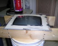
I'll be heating the plexi in the kitchen oven inside the aluminum frame I just half-made. My vacuum frame is built to sit on a 5 Gallon Dough Pail so it's at a comparable work height for me sitting on a $4.99 Oak Stool from Goodwill while watching the acrylic droop.
The bucket also makes for a lot of space underneath for the neck of the CRT . . .
. . . they're usually free, even in food grade if you keep your eyes peeled, but they're only a couple of bucks at a DIY Emporium . . .
. . . if the oak stool makes my @$$ sore, I've got a nice soft "bucket" seat top for another dough pail! [] ]'>
No $60 Japanese Saws have been used in the project . . . so far . . .
. . . now if I could just find my hole saws! :-/
http://warmplastic.com/#vf
They spec a higher temperature/shorter time cycle for heating than most . . . we'll see.
My HowTo shots of this project are focused more upon using simple, basic, inexpensive tools to make the toys for the most part. Sort of like "The Woodwright's Workshop" get'er done just good enough to do the job with the basics of a "My First Toolbox Kit" vs. "Norm Owns the Delta Tool Company & Workshop" model of here's how to do a perfect job using a gazillion dollars worth of tools with $100 and beaucoups time spent just on making the jig to do it that way.
Of course, a few of the tools I've used aren't inexpensive, but you can make due with the simple versions where I've run out of patience with the K*I*S*S & under budget methodology.
I used to enjoy both shows, but my son and I watched the The Woodwright's Workshop and Wood Carving with Dick Butz together every Saturday morning together, so that approach has a lot of sentimental value.
I'll be heating the plexi in the kitchen oven inside the aluminum frame I just half-made. My vacuum frame is built to sit on a 5 Gallon Dough Pail so it's at a comparable work height for me sitting on a $4.99 Oak Stool from Goodwill while watching the acrylic droop.
The bucket also makes for a lot of space underneath for the neck of the CRT . . .
. . . they're usually free, even in food grade if you keep your eyes peeled, but they're only a couple of bucks at a DIY Emporium . . .
. . . if the oak stool makes my @$$ sore, I've got a nice soft "bucket" seat top for another dough pail! [
] ]'>No $60 Japanese Saws have been used in the project . . . so far . . .
. . . now if I could just find my hole saws! :-/
Pictures please...
Mr .. Burpin,,, Pizza eatin.... 3 liter guzzlein... VHS pron watchin... err i mean... lol I bet you have a beta max too.....
Mr .. Burpin,,, Pizza eatin.... 3 liter guzzlein... VHS pron watchin... err i mean... lol I bet you have a beta max too.....
:lol: good one! I ran out of coffee so I had cold pepperoni pie and dr. perky for breakfast and then took a two hour nap! :approve:
Hard to Kill was excellent for the genre BTW. Kinda like Road House without the charm with a tragedy/coma twist.
No BetaMax or LaserDisk players, but several VHS players in stock as backup and for loaning movies to the technologically impaired.
No time for pic-postin' for now, gotta get some results TODAY!!!!! Just takin' the pics of the process may push it into a third day as it is.
Hard to Kill was excellent for the genre BTW. Kinda like Road House without the charm with a tragedy/coma twist.
No BetaMax or LaserDisk players, but several VHS players in stock as backup and for loaning movies to the technologically impaired.
No time for pic-postin' for now, gotta get some results TODAY!!!!! Just takin' the pics of the process may push it into a third day as it is.
. . . #2 fail! But it's gonna look really cool when I cut it to size on the bandsaw and fit it into the ZipPlus for a piccie! ;D
Lower temperature/longer time cycle needed: 350 degrees/5 Minutes put the molten, bubble-boiled slag of plexi on the floor of my baking pan. :O
I need to get a new light bulb for the oven and some bricks to set the frame on so I can see it better.
I'm gonna have to finish the frame up so it'll clamp the plexi on all four sides and put a gasket around the edge of the vacuum frame . . .
. . . maybe just one more try for tonight though . . . the still oven's hot . . . }
Lower temperature/longer time cycle needed: 350 degrees/5 Minutes put the molten, bubble-boiled slag of plexi on the floor of my baking pan. :O
I need to get a new light bulb for the oven and some bricks to set the frame on so I can see it better.
I'm gonna have to finish the frame up so it'll clamp the plexi on all four sides and put a gasket around the edge of the vacuum frame . . .
. . . maybe just one more try for tonight though . . . the still oven's hot . . . }
Third try isn't exactly charming, but it's lookin' a lot more presentable!
Several lessons learned:
Don't pay the site in the link above much attention when it comes to time/temperature . . .
. . . 250°F/longer heating time should work better for 1/8" clear plexi . . .
. . . 300°F still caused a few bubbles to boil up in the plexi, but none nearly as bad as having a dead pixel . . .
. . . when using empty cans in an oven to hold up the frame . . . remove the paper first . . .
. . . it may not be Fahrenheit 451, but 300°F will squeeze some smoke outta can labels for the first couple of minutes! :O
We knew this already from a link posted earlier: thinner material should be used to form a "Plexi CRT Face" for an LCD . . .
. . . but I'm trying to tweak the process for making a MacQuarium Face. }
Pics of the plexi inside the ZipPlus sometime tomorrow evening.
Gotta get to bed . . . this MON-TUE "weekend" has drawn to a close and 7AM is "Monday morning" in my work life.
Several lessons learned:
Don't pay the site in the link above much attention when it comes to time/temperature . . .
. . . 250°F/longer heating time should work better for 1/8" clear plexi . . .
. . . 300°F still caused a few bubbles to boil up in the plexi, but none nearly as bad as having a dead pixel . . .
. . . when using empty cans in an oven to hold up the frame . . . remove the paper first . . .
. . . it may not be Fahrenheit 451, but 300°F will squeeze some smoke outta can labels for the first couple of minutes! :O
We knew this already from a link posted earlier: thinner material should be used to form a "Plexi CRT Face" for an LCD . . .
. . . but I'm trying to tweak the process for making a MacQuarium Face. }
Pics of the plexi inside the ZipPlus sometime tomorrow evening.
Gotta get to bed . . . this MON-TUE "weekend" has drawn to a close and 7AM is "Monday morning" in my work life.
I'm home with new materials to complete the frame, but too pooped to play. I'll try to figure out how to take some shots of blank #3, I got some O Rings to smoosh in between the plexiglass face and a #10 washer under the retaining bolts, I've got great contact top and on one side, decent on the other side and a small gap all across the bottom, but not bad at all.
I'll work on getting some pics up before I fall asleep . . . |)
I'll work on getting some pics up before I fall asleep . . . |)
This is just attempt #3, so be kind . . .
. . . I went way out of my way to light this to make it look as bad a possible . . .
. . . just wait'll you get a load of the first two! :lol:
There are a pile of factors that could be why this turned out with a lot of flaws, but I'm really happy with the progress made in three attempts . . .
. . . best foot forward . . .
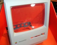
. . . better than anticipated, especially when smoke billowed out of the oven from the roasted can labels! 8-o
Decent lookin toes on best foot . . .
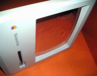
. . . nice fit on top and right sides . . .
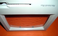
. . . nice top edge fit . . .
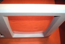
. . . nice right edge fit . . .
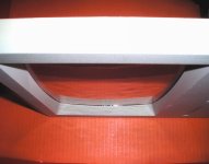
. . . rough fit on the left edge . . .
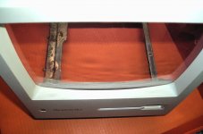
. . . bottom edge had a definite gap as well . . .
. . . but the bolt holes got screwed up so there's next to nothing holding the lower left corner . . .
. . . so the bottom and and left sided attached to that corner aren't fitting well . . .
. . . we'll see what happens when I finish the frame, mount the foam gasket around the edge of the base and tweak time/temp curves . . .
. . . and use the four concrete bricks I brought home for non-flammable supports! :approve:
. . . I went way out of my way to light this to make it look as bad a possible . . .
. . . just wait'll you get a load of the first two! :lol:
There are a pile of factors that could be why this turned out with a lot of flaws, but I'm really happy with the progress made in three attempts . . .
. . . best foot forward . . .
. . . better than anticipated, especially when smoke billowed out of the oven from the roasted can labels! 8-o
Decent lookin toes on best foot . . .
. . . nice fit on top and right sides . . .
. . . nice top edge fit . . .
. . . nice right edge fit . . .
. . . rough fit on the left edge . . .
. . . bottom edge had a definite gap as well . . .
. . . but the bolt holes got screwed up so there's next to nothing holding the lower left corner . . .
. . . so the bottom and and left sided attached to that corner aren't fitting well . . .
. . . we'll see what happens when I finish the frame, mount the foam gasket around the edge of the base and tweak time/temp curves . . .
. . . and use the four concrete bricks I brought home for non-flammable supports! :approve:
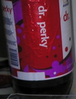
Lots of caffeine in Dr. Perky?
lookin good!
THX, I figured out that each of the lumps coincide with a bubble that increased the thickness of the plexi. They showed up great in the pics, not nearly as noticeable IRL
I prefer Dr. Pizzaz, actually, both have adequate amounts of caffeine and sugar to keep me going. Water if I don't need those two active ingredients.
I prefer Dr. Pizzaz, actually, both have adequate amounts of caffeine and sugar to keep me going. Water if I don't need those two active ingredients.
You could buff out the imperfections since it'll be behind the bezel, right? Then you'll have a nice, smooth fit. Though to tell you the truth, I think it looks fine anyway. Not sure the CRT was that tight of a fit, either.
So what's the goal here, acrylic over glass? Or is this another fish tank in the making?
From his very hard-to-follow posts in both this and the ATOMICZipMacPlus/MacQuarium thread, I gather he's trying to make a fish tank out of the CRT or something.
Thanks, but this one is just experimental, I'll be perfecting the process over time. At 250°F w/longer warmup period, there likely won't be any internal gas bubbles causing deformation. I've already figured a way to get the mounting ears and surfaces a bit closer to spec with the 1/8" plexi.
This one is just good enough for me to take some fine wet sandpaper or a buffing wheel and rouge to the backside to matte it out. I've been itching to play with the optical setup of the rear projection system for the MacintoshClassicIIIColorTVp™ for a couple of years now.
Once I've learned enough by fine tuning this setup, it's on to bigger and better for the long term ClearProtoHoaxMac™ Project. }
This one is just good enough for me to take some fine wet sandpaper or a buffing wheel and rouge to the backside to matte it out. I've been itching to play with the optical setup of the rear projection system for the MacintoshClassicIIIColorTVp™ for a couple of years now.
Once I've learned enough by fine tuning this setup, it's on to bigger and better for the long term ClearProtoHoaxMac™ Project. }
It's good to know anyway for peeps wanting to do the LCD hack. Having a perfectly curved acrylic is a lot easier than cutting the glass off the CRT (like one other user did.)
That'd be it, I'm trying to figure out how to fab a MacQuarium insert made from blanks vacuum formed over the face and most of the tube of the CRT. That's why I'm experimenting with the 1/8" acrylic, I've go a lot of it on hand and a ready source for more scrap of approximately the right size.
Ideally, I'd like to do a deep draw down over the portion of the tube forward of the coils. I'll use a glass cutter and knock the neck off to clamp inside the coil assembly so that will look stock. Then I'll knock the part covered by the coil assembly off and reconstruct it with epoxy putty with a flat ended cone to which the coil assembly will be glued.
I'll also be adding a "goiter" up near the front, A/B side of the tube that will be the highest point and as flat as possible so I can use a hole saw to cut a port in the top. This will sized large enough to fit all the junk I want to have inside the MacQuarium through it and then plug up with a standard stopper or waterproof lid of some kind. Pumped air in, and return air out, lines will be set into the stopper/lid, with the air pump located remotely and above the water level to avoid siphoning off the water in a failure of any kind. This will keep the pump noise away from my workstation, the bubbling noise is relaxing, the pump noise is not. Being located at the top, front, A/B side of the fake CRT will keep the "goiter/access port" out of sight from behind the clear case portions of the ATOMicZipMacPLUS/MacQuarium™
I've got 1/16" acrylic to make a few "LCD Bubbles" for the 9" CRT. When I do the up-scaled vacuum forming unit, I'll be making an LCD Bubble for one of my 12"RGB'zaToppers. If all my stalled trades go through, there will be a maxed out 1400c/G3 in the RGB's shell with the 1400's LCD peeking out from behind the bubble. The 12"RGB's guts will then be available to be housed in a ClearProtoHoaxMac AIO of, as yet, undetermined type, or into storage as backup for the working unit. [
] ]'>I'm going to see if I can do another trial run tonight . . .
With any luck at all, I can glass-cut and knock the tube from the frame & face of the 9"CRT when I'm done with the MacQuarium, we'll see . . .

Any way you could create a concave mold to just let the acrylic droop into instead of a convex mold that it has to droop around?
Seems like you could control the margins/mounting-tabs better that way.
Seems like you could control the margins/mounting-tabs better that way.
Dunno, negative forming bucks should work well for case parts, better yet, choose the right fabric or textured surface for lining the negative buck, then blow mold the case part and the outside of the part might approximate a textured Mac.
Reverse plaster casting coupled with some flexible rubber "diamond plate" liner to match a compact's side panel curves for a blow molding seems . . . hrmmm? }
Maybe a clear diamond plate RuggedizedProtoHoaxBook™ . . . ;D
As vacuum forming bucks go, it doesn't get much better than the real glass deal.
Reverse plaster casting coupled with some flexible rubber "diamond plate" liner to match a compact's side panel curves for a blow molding seems . . . hrmmm? }
Maybe a clear diamond plate RuggedizedProtoHoaxBook™ . . . ;D
As vacuum forming bucks go, it doesn't get much better than the real glass deal.
Well, strictly speaking, your positive-molded faceplate is going to be 1/8" too big, but I don't suppose that's going to matter much.
True enough, but the curvature is "near perfect" and surface finish is perfection itself. The lengthening of the "radius" of the various French Curves isn't noticeable even using 1/8" MacQuarium thicknessed plexi. Gross changes to the curvature are hidden behind the bezel, a very convenient happenstance, that. The changes for LCD Bubble thickness Plexi will be negligible, even behind the bezel.
I'll do a comparison shot after I've done the "Ground Glass" treatment to the rear surface of a Projection Screen/Bubble. I'm not sure what the final thickness of that will be, it will be tweaked to give the closest approximation of an image behind a CRT face. It will very likely have a matte Plexi front surface, mimicking the anti glare coating of the 9" CRT. Variable separation between the LCD Bubble surface and LCD will likely make this trick unworkable, but I'm hoping a Semi-Gloss Clearcoat will work. The glossier the better for the MacQuarium version.
I'm using a piece of 1/8" plexi as a spacer. It's got a horrible looking hole cut in it that barely matches the outer edge of the CRT. I have it sitting on top of two 6 ply Showcard spacers. For comparison Dime Store Poster Board is somewhere between 2 and 4 ply, dunno never used it.
Thankfully, the one process image I've posted illustrates the layering quite well.

______________ Formed Plexi _________________ - 1/8" thickness for Plastic Fish Habitat Containment Vessel
_____________ 1/8" Plexi Spacer _______________ - provides a flat rear surface, intended to be solvent welded to flat surface of rear section
____ Doubled 6 ply cardboard ear surround ____ - matches thickness of mounting ears on metal CRT banding
________ 1/8" Plexi Vacuum Base Surface _______ - supports CRT acting as forming buck, crack in between is application specific "pegboard hole" analog
_______________Wood Frame___________________ - nominal 1x4 scrap (3/4" x 3 1/2" actual size)
________ Dough Pail frame support _____________ - completes deep vacuum frame while acting as work height support, reducing frame size for storage as well
For forming an LCD Bubble the spacer will be omitted and the ear surround is optional.
I'll be making a 6 ply cardboard spacer for the next test . . .
. . . lots of fun coming up in ironing out the variables for the three, very different, applications of the final products . . .
. . . we'll see! ;D
edit: this is great, B, I'll post the process piccies and explanations as responses to questions, so ask away!. I can finish up with any HowTo details after the Q&A session.
That will save me a lot of work and, hopefully, make for an uncharacteristically easy to follow hack thread for a change . . .
. . . "easy" being a relative term, of course! :lol:
I'll do a comparison shot after I've done the "Ground Glass" treatment to the rear surface of a Projection Screen/Bubble. I'm not sure what the final thickness of that will be, it will be tweaked to give the closest approximation of an image behind a CRT face. It will very likely have a matte Plexi front surface, mimicking the anti glare coating of the 9" CRT. Variable separation between the LCD Bubble surface and LCD will likely make this trick unworkable, but I'm hoping a Semi-Gloss Clearcoat will work. The glossier the better for the MacQuarium version.
I'm using a piece of 1/8" plexi as a spacer. It's got a horrible looking hole cut in it that barely matches the outer edge of the CRT. I have it sitting on top of two 6 ply Showcard spacers. For comparison Dime Store Poster Board is somewhere between 2 and 4 ply, dunno never used it.
Thankfully, the one process image I've posted illustrates the layering quite well.
______________ Formed Plexi _________________ - 1/8" thickness for Plastic Fish Habitat Containment Vessel
_____________ 1/8" Plexi Spacer _______________ - provides a flat rear surface, intended to be solvent welded to flat surface of rear section
____ Doubled 6 ply cardboard ear surround ____ - matches thickness of mounting ears on metal CRT banding
________ 1/8" Plexi Vacuum Base Surface _______ - supports CRT acting as forming buck, crack in between is application specific "pegboard hole" analog
_______________Wood Frame___________________ - nominal 1x4 scrap (3/4" x 3 1/2" actual size)
________ Dough Pail frame support _____________ - completes deep vacuum frame while acting as work height support, reducing frame size for storage as well
For forming an LCD Bubble the spacer will be omitted and the ear surround is optional.
I'll be making a 6 ply cardboard spacer for the next test . . .
. . . lots of fun coming up in ironing out the variables for the three, very different, applications of the final products . . .
. . . we'll see! ;D
edit: this is great, B, I'll post the process piccies and explanations as responses to questions, so ask away!. I can finish up with any HowTo details after the Q&A session.
That will save me a lot of work and, hopefully, make for an uncharacteristically easy to follow hack thread for a change . . .
. . . "easy" being a relative term, of course! :lol:
How much did the last modicum of patience go for on eBay? :-/
I will have to try to develop more patience for this, but I'm really having a blast! ;D
Go some new scrap plexi, I knew it was different from what I'd been using and I got a tad impatient . . .
. . . more bubbles because I kicked the temp up to 275°F again after 250°F didn't get it to droop . . .
. . . it actually bowed upward at first, so I pulled it out and the vacuum didn't touch it . . .
. . . back in the oven it went and I waited forever before it finally drooped a bit after I cranked up the temp.
#4 will make a good marking template for future trials . . .
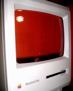
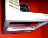
#2 will likely remain my all-time fave . . .
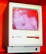
. . . it just cries out for a Чорнобильська property tag and a bit of case slagging!)
I will have to try to develop more patience for this, but I'm really having a blast! ;D
Go some new scrap plexi, I knew it was different from what I'd been using and I got a tad impatient . . .
. . . more bubbles because I kicked the temp up to 275°F again after 250°F didn't get it to droop . . .
. . . it actually bowed upward at first, so I pulled it out and the vacuum didn't touch it . . .
. . . back in the oven it went and I waited forever before it finally drooped a bit after I cranked up the temp.
#4 will make a good marking template for future trials . . .
#2 will likely remain my all-time fave . . .
. . . it just cries out for a Чорнобильська property tag and a bit of case slagging!
)
The warming and machining characteristics of the material used for #4 lead me to believe that it's Polycarbonate and not Acrylic.
It took far longer to warm up than the same thickness Acrylic, the bubbles from overheating deformed the structure of the material far less than in the other tests. Other than two larger bubbles, the rest remain almost unnoticeable in size or distortion when held up against the LCD in front of me. [] ]'>
This stuff seems to be a lot more brittle than Acrylic, drilling the mounting holes caused considerably more "chipout" and a sharper noise at breakthrough. When I was marking the holes while the the cooled material was still on the CRT, I was surprised by how quickly the first hole broke through. I was testing drill-through with the formed blank still on top of the mounting ears at the time, which was a bad idea. Chipout was markedly worse, which was expected, but he hairline beginnings of a crack in the formed piece resulted, which was semi-expected. However it grew to about 3/4" in length from the slight pressures I used in mounting it for the photos, which was not.
Acrylic shouldn't have done that, from what I've experienced in APlexi fabrication in the past. I'll test pieces of this against Acrylic with MEK when I get a chance. *****
I'll be thinking about ways to form and fuse together more complex parts for the MacQuarium project. In this round of experimentation I've demonstrated that there's not enough room within the ZipPlus bezel to achieve a flat surface to fuse to the rear portion of a vacuum formed CRT using the current process. I'll need to join more parts along compound curves if I can't noodle out a tweak for this process. I'll also post some piccies of the apparatus fabrication, process and results when I get a chance to prep them for upload. That way I don't have to worry about documentation or sticking to the use of K*I*S*S tools and methods of construction the next time around! [] ]'>
It turns out that what I've been calling 1/8" is really 1/16" material. I finally put the digital calipers on it and immediately shook my head in dismay, that's one BIG oopsie that I never would have made back in the day, but everything about this exercise has been "hurry up and see what happens" methodology, right down to the photographic documentation. I may do a few more experimental runs using the ersatz 1/8" Acrylic just to see what happens.
I'll be re-thinking the process and going about it a lot more deliberately after properly designing and building a full size vacuum forming apparatus from new materials instead of wingin' it with the scrap I had on hand. Plaster casting experimentation in negative/positive/thicknessing iterations is next up on the list. As is the casting and finishing of "lost plaster" bucks for forming fairly complex parts with flat mating surfaces in hidden places.
Does anyone already know how to remove the CRT's metal mounting band using a non-destructive process? [}] ]'>
*****WARNING: Methyl Ethyl Keytone is very nasty stuff, read the label several times if you consider buying a can. Stick with Acrylic cements if you're not experienced in handling HazMats. MEK is the active ingredient in cements for Acrylic, PVC, etc. which is the reason they all warn to use them only in well ventilated areas. The thickening agents in cements makes them less volatile, a bit slower working and a lot less dangerous. The thickening agent for Acrylic Cements is clear acrylic that is entirely dissolved in MEK.
Many years ago they began selling consumer rated Acrylic Cements and water based Contact Cements for doing laminate work. Use a respirator if you're smart/concerned, I use one using straight MEK even outdoors.
It took far longer to warm up than the same thickness Acrylic, the bubbles from overheating deformed the structure of the material far less than in the other tests. Other than two larger bubbles, the rest remain almost unnoticeable in size or distortion when held up against the LCD in front of me. [
] ]'>This stuff seems to be a lot more brittle than Acrylic, drilling the mounting holes caused considerably more "chipout" and a sharper noise at breakthrough. When I was marking the holes while the the cooled material was still on the CRT, I was surprised by how quickly the first hole broke through. I was testing drill-through with the formed blank still on top of the mounting ears at the time, which was a bad idea. Chipout was markedly worse, which was expected, but he hairline beginnings of a crack in the formed piece resulted, which was semi-expected. However it grew to about 3/4" in length from the slight pressures I used in mounting it for the photos, which was not.
Acrylic shouldn't have done that, from what I've experienced in APlexi fabrication in the past. I'll test pieces of this against Acrylic with MEK when I get a chance. *****
I'll be thinking about ways to form and fuse together more complex parts for the MacQuarium project. In this round of experimentation I've demonstrated that there's not enough room within the ZipPlus bezel to achieve a flat surface to fuse to the rear portion of a vacuum formed CRT using the current process. I'll need to join more parts along compound curves if I can't noodle out a tweak for this process. I'll also post some piccies of the apparatus fabrication, process and results when I get a chance to prep them for upload. That way I don't have to worry about documentation or sticking to the use of K*I*S*S tools and methods of construction the next time around! [
] ]'>It turns out that what I've been calling 1/8" is really 1/16" material. I finally put the digital calipers on it and immediately shook my head in dismay, that's one BIG oopsie that I never would have made back in the day, but everything about this exercise has been "hurry up and see what happens" methodology, right down to the photographic documentation. I may do a few more experimental runs using the ersatz 1/8" Acrylic just to see what happens.
I'll be re-thinking the process and going about it a lot more deliberately after properly designing and building a full size vacuum forming apparatus from new materials instead of wingin' it with the scrap I had on hand. Plaster casting experimentation in negative/positive/thicknessing iterations is next up on the list. As is the casting and finishing of "lost plaster" bucks for forming fairly complex parts with flat mating surfaces in hidden places.
Does anyone already know how to remove the CRT's metal mounting band using a non-destructive process? [}
] ]'>*****WARNING: Methyl Ethyl Keytone is very nasty stuff, read the label several times if you consider buying a can. Stick with Acrylic cements if you're not experienced in handling HazMats. MEK is the active ingredient in cements for Acrylic, PVC, etc. which is the reason they all warn to use them only in well ventilated areas. The thickening agents in cements makes them less volatile, a bit slower working and a lot less dangerous. The thickening agent for Acrylic Cements is clear acrylic that is entirely dissolved in MEK.
Many years ago they began selling consumer rated Acrylic Cements and water based Contact Cements for doing laminate work. Use a respirator if you're smart/concerned, I use one using straight MEK even outdoors.
You could get around the extra size issue by doing a double process...
Form the nessecary parts as you have been, then form new parts over the inside of those parts. Essentially, you want to make a mould from the original, and then make a new part from the mould. I know it uses twice as much plastic and takes twice as long, but if you're tight for space then it might be a good method.
Form the nessecary parts as you have been, then form new parts over the inside of those parts. Essentially, you want to make a mould from the original, and then make a new part from the mould. I know it uses twice as much plastic and takes twice as long, but if you're tight for space then it might be a good method.