

Thread
LCIII Recap - Apple design fault -47uF reversed!
Hi,
Am I the first person to discover this? C22 (the 47uF capacitor in the corner beside the power supply connector) on our LCIII has the + sign on the PCB on the negative capacitor terminal. This capacitor is between -5V and ground.
The original C22 electrolytic on this board, and on another LCIII we have here, are installed the wrong way round electronically but the right way round according to the PCB silk screen. In other words I think all the LCIIIs ever made on those two board versions went out the door with C22 polarised the wrong way!
I only discovered this because I recapped this LCIII with tantalums and after a few hour's use the -5V supply was dropping to -2.1V. Putting an ammeter in series I found the current went to about 1.3A (far more than the 75mA rating). I replaced the cap with the -ve terminal soldered where the + sign is on the board and I have no problems :b&w:
As far as I can tell the -5V supply is only for the RS422 driver chips for the Appletalk and Modem ports. Would that be correct?
Am I the first person to discover this? C22 (the 47uF capacitor in the corner beside the power supply connector) on our LCIII has the + sign on the PCB on the negative capacitor terminal. This capacitor is between -5V and ground.
The original C22 electrolytic on this board, and on another LCIII we have here, are installed the wrong way round electronically but the right way round according to the PCB silk screen. In other words I think all the LCIIIs ever made on those two board versions went out the door with C22 polarised the wrong way!
I only discovered this because I recapped this LCIII with tantalums and after a few hour's use the -5V supply was dropping to -2.1V. Putting an ammeter in series I found the current went to about 1.3A (far more than the 75mA rating). I replaced the cap with the -ve terminal soldered where the + sign is on the board and I have no problems :b&w:
As far as I can tell the -5V supply is only for the RS422 driver chips for the Appletalk and Modem ports. Would that be correct?
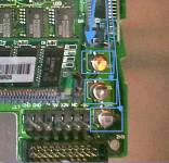
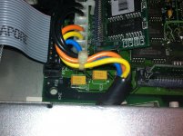
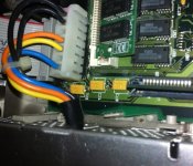
Thanks for the photos. I am saying that I am pretty sure that you have the C22 cap, the one on the left in the bottom two photos, round the wrong way.
If you put a voltmeter onto either end of C22 the way you have it, you will see that the cap should be round the other way.
I know the LCIII will work with the capacitor round the wrong way for a while but I am not sure how long.
If you put a voltmeter onto either end of C22 the way you have it, you will see that the cap should be round the other way.
I know the LCIII will work with the capacitor round the wrong way for a while but I am not sure how long.
you might want to take this to the lists as well...
https://groups.google.com/forum/?fromgroups#!forum/vintage-macs
http://www.classiccmp.org/lists.html
and maybe the 68kmla IRC as well.
https://groups.google.com/forum/?fromgroups#!forum/vintage-macs
http://www.classiccmp.org/lists.html
and maybe the 68kmla IRC as well.
Yes Rick, you are correct.
If you are using those orangish tantalums, with the darker orange bar indicating the + side, you need to put that on the ground. So if you look at the photos uniserver posted. The one on the left hand end should face the opposite way from the other two in that row.
I find it amazing that all those LC's were produced with the C22 electrolytics round the wrong way. The only explanation I can see for why there weren't any failures is that the electrolytic failed open circuit and the capacitor in the power supply itself was good enough. There is very little load on the -5V supply.
If you are using those orangish tantalums, with the darker orange bar indicating the + side, you need to put that on the ground. So if you look at the photos uniserver posted. The one on the left hand end should face the opposite way from the other two in that row.
I find it amazing that all those LC's were produced with the C22 electrolytics round the wrong way. The only explanation I can see for why there weren't any failures is that the electrolytic failed open circuit and the capacitor in the power supply itself was good enough. There is very little load on the -5V supply.
That looks like an interesting catch, but surprising that failures have not been noticed over all these years.
It could be a problem of semiotics. The + sign seems to identify polarity correctly in relation to common GND, but incorrectly in relation to potential across the specific capacitor. I wonder if the PCB designers and the assemblers apply different standards to identifying polarity on a negative voltage. Somebody here will know... :?:
Rick
It could be a problem of semiotics. The + sign seems to identify polarity correctly in relation to common GND, but incorrectly in relation to potential across the specific capacitor. I wonder if the PCB designers and the assemblers apply different standards to identifying polarity on a negative voltage. Somebody here will know... :?:
Rick
It is a typo on the silkscreen and caps were installed the WRONG way on the two LCIII's we have (by the manufacturer)
See attached photo. The meter probes have the red (+ve input to the meter) on the leg of the positive side of the capacitor. You can see it reads -4.96V.
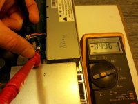
See attached photo. The meter probes have the red (+ve input to the meter) on the leg of the positive side of the capacitor. You can see it reads -4.96V.
The capacitor is just a smoothing capacitor on the -5V supply. I think the -5V supply is only used for the printer (appletalk) and modem port drivers. Since the aluminium can capacitors which were on the LCIII as they came out of the factory did not cause a failure I wouldn't worry about LCIIIs which haven't been recapped.
I have no idea how other LCIIIs that have been recapped have stood up. It seems that tantalum capacitors are the favourite ones to use for the recap. The tantalum that I put in facing the way the original silkscreen showed, failed by starting to go short circuit. It was dragging about 1.3A from 75mA the -5V supply and dragged it down to -2.1V. I have no idea which would have broken first, the power supply or the capacitor, if I left it going for longer. I doubt whether the Modem or Printer ports would work properly with a -2.1V supply.
Maybe the tantalums other people are using to recap their boards are more tolerant of being reverse biased.
I am not a Mac user but I was, in the early 1990's, when we made the machine which was controlled by the LCIII that I am trying to back up. So I know nothing of how the PCB layout changed with subsequent Macs.
I have no idea how other LCIIIs that have been recapped have stood up. It seems that tantalum capacitors are the favourite ones to use for the recap. The tantalum that I put in facing the way the original silkscreen showed, failed by starting to go short circuit. It was dragging about 1.3A from 75mA the -5V supply and dragged it down to -2.1V. I have no idea which would have broken first, the power supply or the capacitor, if I left it going for longer. I doubt whether the Modem or Printer ports would work properly with a -2.1V supply.
Maybe the tantalums other people are using to recap their boards are more tolerant of being reverse biased.
I am not a Mac user but I was, in the early 1990's, when we made the machine which was controlled by the LCIII that I am trying to back up. So I know nothing of how the PCB layout changed with subsequent Macs.
Remember that on aluminum electrolytics, the polarization mark indicates the negative terminal, but on tantalums the mark indicates the positive one. As others have indicated, if this is on the -5V rail, then the + side should be to ground. Nevertheless, you should easily be able to tell which terminal is more positive with your trusty voltmeter. If you measure the voltage across the cap as +5V and the positive lead is connected to the + side of the cap, then it's installed the right way.
Sounds like a design mistake to me! Very nice catch, paul.gaastra. That picture with your multimeter definitely proves, IMO, that the silkscreen (and the capacitor placement) was wrong. As far as I know, and my EE coworker agrees, there should never be a negative potential across an electrolytic (or tantalum) capacitor. They've been known to make exciting bangs when installed in reverse.
http://en.wikipedia.org/wiki/Electrolytic_capacitor#Polarity
Now I'm curious about other Mac models' motherboards that might have capacitors on the -5V rail...
http://en.wikipedia.org/wiki/Electrolytic_capacitor#Polarity
Now I'm curious about other Mac models' motherboards that might have capacitors on the -5V rail...
Just found the -5V rail on my IIci on the RS-422 driver chips. There's a 47 uF capacitor near them (C5) with the negative edge hooked to -5V and the positive edge hooked to GND. So they did it correctly on the IIci for example. Yep...must just be a mistake on the LC III.
Can some one please take a nice picture so people can visually see how it should be and post it in this LC-III Caps! thread?
viewtopic.php?f=9&t=19776&p=188206#p188206
viewtopic.php?f=9&t=19776&p=188206#p188206
Hmm... Fascinating!
However, why hasn't it manifested itself as a problem after all these years?
If this were really a bad mistake, then how come everybody's LC III logic boards haven't blown up? It seems like the LC III would've been recalled practically before being put into production if it were that bad.
Oh, well... I guess this is just further proof that there's always more to learn!
c
However, why hasn't it manifested itself as a problem after all these years?
If this were really a bad mistake, then how come everybody's LC III logic boards haven't blown up? It seems like the LC III would've been recalled practically before being put into production if it were that bad.
Oh, well... I guess this is just further proof that there's always more to learn!
c
Uniserver said
It's no use me taking a photograph of the board I recapped correctly because I put the tantalums on upside down and soldered fuse wire to the pads. So you can't see the capacitor markings. I do that because I am afraid of shorting the pads to the ground plane. Generally the terminals of SMT tantalums are wider than the pad of the original electolytics. It makes for a lot of work and really makes a mess.
I've been thinking about that. This rail serves the RS422 ports, driving the negative half of the TX and RX differential circuits. The positive sides of each signal are correctly filtered. So I'm guessing that the filter isn't essential but is there as standard design practice to protect the signal when it is close to limit of specs - say with a very long cable to a printer or modem. It's fairly low current and short duty cycle and the overvoltage on the reversed cap might even be within, or not far outside, the tolerance of the original electrolytics. The ESR generates heat, but the aluminium cans might dissipate this better than the replacement poly tantalums, and so last indefinitely with moderate or low usage.
It could be interesting to test a machine in the original state, just by finger touch on the cap, to see whether the reversed cap is noticeably warmer than its neighbours when in use, say with a printer attached to the port. I don't have one of the relevant machines to test myself.
I'm an amateur at this, and would be happy to hear opinion of a proper EE. :-/
Rick
 I wonder if they knew about it and didn't bother fixing it, or if this is something new that no one noticed before? Certainly news to me.
Someone mentioned before on this thread that it's common for Electrolytic and Tantalum capacitors to have opposite polarity markings, are we *absolutely positive* that doesn't explain the confusion here?
I *seriously* doubt these machines shipped with an electrolytic capacitor that was put in backwards. Electrolytics have this nasty habit of blowing up like bombs when run in reverse (seen it in the flesh several times), and even if by some miracle that didn't happen it'd still heat up and act like a (partially) shorted circuit. This is the sort of thing the manufacturer would have noticed after shipping a few thousand units.
I *seriously* doubt these machines shipped with an electrolytic capacitor that was put in backwards. Electrolytics have this nasty habit of blowing up like bombs when run in reverse (seen it in the flesh several times), and even if by some miracle that didn't happen it'd still heat up and act like a (partially) shorted circuit. This is the sort of thing the manufacturer would have noticed after shipping a few thousand units.
I thought the same way at first -- we have to be thinking something wrong -- but look at the multimeter picture closely. There's -5V across that capacitor. And bbraun confirmed the same capacitor orientation on his LC III.
It's backwards. Unless Apple had a special batch of electrolytics made that had the black mark on the positive side...and used it only on that capacitor...
I don't understand why it hasn't popped either. My understanding is that electrolytic capacitors in reverse can explode nastily. Is there any explanation? Not enough current available from the -5V rail to do any harm? Maybe the original capacitor, even though it has a polarization mark on it, happens to be bipolar? I'm just trying to think of any rational explanation other than "it's backwards" and I'm coming up blank.

Yes, I think we may be seeing a situation where an electrolytic is more tolerant than a tantalum. Still waiting for any report of this reversed electrolytic actually failing in normal use. If there are cases of it failing before the others on the positive rails, we could infer that it had been carrying a marginally greater heat load because of the ESR from the reversed polarity.
Rick
Rick
could this be a solution?
http://www.mouser.com/ProductDetail/Taiyo-Yuden/EMK325BJ476MM-T/?qs=sGAEpiMZZMuMW9TJLBQkXnpMKdRe6%2fORaxesfjtxlnQ%3d
100: $0.735
Multilayer Ceramic Capacitors MLCC - SMD/SMT CAP MLCC 1210 16V X5R 47uF 20%
http://www.mouser.com/ProductDetail/Taiyo-Yuden/EMK325BJ476MM-T/?qs=sGAEpiMZZMuMW9TJLBQkXnpMKdRe6%2fORaxesfjtxlnQ%3d
100: $0.735
Multilayer Ceramic Capacitors MLCC - SMD/SMT CAP MLCC 1210 16V X5R 47uF 20%
Brilliant, uniserver! A non polarised replacement!
I'm no expert on whether the esr is OK on those, but it does say it's low. I am continually amazed at how technology is advancing. We would never have thought of getting a 47uF capacitor in ceramic just a few years ago.
However, it's no better solution than putting a polarised electrolytic or tantalum in with the correct polarity.
Maybe another solution is to leave C22 off the pcb.
Maybe someone like the techknight has an oscilloscope and can put a probe on the -5v supply when two of his Macs are transfering a file on Appletalk and see if the supply is degraded at all with no C22. I've seen his YouTube videos. He knows what he's talking about.
I'm no expert on whether the esr is OK on those, but it does say it's low. I am continually amazed at how technology is advancing. We would never have thought of getting a 47uF capacitor in ceramic just a few years ago.
However, it's no better solution than putting a polarised electrolytic or tantalum in with the correct polarity.
Maybe another solution is to leave C22 off the pcb.
Maybe someone like the techknight has an oscilloscope and can put a probe on the -5v supply when two of his Macs are transfering a file on Appletalk and see if the supply is degraded at all with no C22. I've seen his YouTube videos. He knows what he's talking about.
I noticed the same thing when I re-capped mine. I happened to be looking at the traces and thought something seemed odd, so I measured it and sure enough, the marking on the board is backward. I had already removed the old capacitor so I'm not sure whether it was installed correctly or not.
There is a similar error on the Electrohome G07 monitor used in a lot of 80s arcade games. One of the capacitors is marked backwards on one side of the board and it was never corrected throughout the production run.
There is a similar error on the Electrohome G07 monitor used in a lot of 80s arcade games. One of the capacitors is marked backwards on one side of the board and it was never corrected throughout the production run.