
Thread
My case for the FloppyEmu!
I was at the doctor's office today for an upper endoscopy, so I got the day off cuz of the anesthesia.
Here's what I worked on, I'm gonna attempt to print it when I get to work tomorrow, see how it fits. It's a case for BMOW's FloppyEmu.
The two square holes in the front are for LEDs. I'm gonna solder a red and green to the status and power LEDs on the board so they'll blink up front. I'm also making buttons that'll fit in the holes on top. Unfortunately I don't think my 3D printer is fine enough detail to put embossed lettering on the case, so I think I'll use water decals.
I added the grooves and rounded corners typical of vintage Macs. Kinda looks like a Lisa from a certain angle... Ooo. Maybe I could make a miniature Lisa case that sits vertically. :lol:

Here's what I worked on, I'm gonna attempt to print it when I get to work tomorrow, see how it fits. It's a case for BMOW's FloppyEmu.
The two square holes in the front are for LEDs. I'm gonna solder a red and green to the status and power LEDs on the board so they'll blink up front. I'm also making buttons that'll fit in the holes on top. Unfortunately I don't think my 3D printer is fine enough detail to put embossed lettering on the case, so I think I'll use water decals.
I added the grooves and rounded corners typical of vintage Macs.
Kinda looks like a Lisa from a certain angle... Ooo. Maybe I could make a miniature Lisa case that sits vertically. :lol: 
 ] ]'>
The tomato is just my random avatar, if you need a logo use this: http://www.bigmessowires.com/bmow-title.png
But shouldn't it have the olePigeon logo?
But shouldn't it have the olePigeon logo?


I'm gonna stop by the stationary store on my way home and get some water decal paper. I'll make a Tomato (like the Apple logo) with the BMOW logo next to it.
We got some new colors in for the 3D printer. We have transparent (which I think I'll start with) plus blue, green, and... a 3rd color I can't remember.
We got some new colors in for the 3D printer. We have transparent (which I think I'll start with) plus blue, green, and... a 3rd color I can't remember.

sorry that is a lot of tomato!
http://en.wikipedia.org/wiki/Tomato
According to FAOSTAT, the top producers of tomatoes (in tonnes) in 2011.[20]
Rank Country Production
(MT)
1 China 48,572,921 <-----------------------------
2 India 16,826,000
3 United States 12,526,070
4 Turkey 11,003,433
5 Egypt 8,105,263
6 Iran 6,824,298
7 Italy 5,950,215
8 Brazil 4,416,652
9 Spain 3,864,120
10 Uzbekistan 2,585,000
I got side tracked looking up if they still call them a fruit
lol:
http://en.wikipedia.org/wiki/Nix_v._Hedden
Nix v. Hedden, 149 U.S. 304 (1893),[1] was a decision by the Supreme Court of the United States that, under U.S. customs regulations, the tomato should be classified as a vegetable rather than a fruit.
one more tidbit:
Italy
The recorded history of tomatoes in Italy dates back to 31 October 1548.
http://en.wikipedia.org/wiki/Tomato
According to FAOSTAT, the top producers of tomatoes (in tonnes) in 2011.[20]
Rank Country Production
(MT)
1 China 48,572,921 <-----------------------------
2 India 16,826,000
3 United States 12,526,070
4 Turkey 11,003,433
5 Egypt 8,105,263
6 Iran 6,824,298
7 Italy 5,950,215
8 Brazil 4,416,652
9 Spain 3,864,120
10 Uzbekistan 2,585,000
I got side tracked looking up if they still call them a fruit
lol:
http://en.wikipedia.org/wiki/Nix_v._Hedden
Nix v. Hedden, 149 U.S. 304 (1893),[1] was a decision by the Supreme Court of the United States that, under U.S. customs regulations, the tomato should be classified as a vegetable rather than a fruit.
one more tidbit:
Italy
The recorded history of tomatoes in Italy dates back to 31 October 1548.
I should probably donate to wikipedia one of those days
Good question, no idea. I'll see if I can figure out the cost somehow. There's gotta be a way to see how much filament is used during a print, then I can divide that into the cost of a spindle of filament.how much do you think it would cost to make one? i'd like one
 ) its bright florescent green
It's about $40 a spool.
I've successfully printed the bottom part of the case, snaps right in. It's perfect.
However, I'm having trouble with the top part. After it finishes processing the model, it wants to fill in the openings (like the holes, the window, and the grooves) with the infil pattern. I don't know why it's doing that. :?: They're supposed to be empty. It shouldn't be filling those areas.
I've set the inil to 0%, I'll see if that works.
I've successfully printed the bottom part of the case, snaps right in. It's perfect.
However, I'm having trouble with the top part. After it finishes processing the model, it wants to fill in the openings (like the holes, the window, and the grooves) with the infil pattern. I don't know why it's doing that. :?: They're supposed to be empty. It shouldn't be filling those areas.
I've set the inil to 0%, I'll see if that works.
Here's the prototype! I already found a few measurement issues, so I've fixed those on the model. Don't know if I'll have enough time to print another one. All in all, not too bad! It's even clear plastic, so you know it's a prototype. 
Not too shabby considering I used a ruler to get the dimensions. Off by a millimeter or so for the opening to the SD card, and the case is a bit short. Was supposed to be flush somewhat flush with the connector (off by about 2 or 3 mm.)
I'll need to file the window down a bit, the LCD didn't quite fit so I had to take it off. I've made it a couple millimeters bigger on the new revision. It kinda bungled the holes, even at 0% infil. Not to worry, can just drill those out easy.


Not too shabby considering I used a ruler to get the dimensions.
Off by a millimeter or so for the opening to the SD card, and the case is a bit short. Was supposed to be flush somewhat flush with the connector (off by about 2 or 3 mm.)I'll need to file the window down a bit, the LCD didn't quite fit so I had to take it off. I've made it a couple millimeters bigger on the new revision. It kinda bungled the holes, even at 0% infil. Not to worry, can just drill those out easy.
Solved the infil issue. There are inside and outside faces for objects, and Google doesn't care which is which. However, the software uses the inside and outside faces for determining where to fill in empty space. So I went through the model and found out that a lot of the faces were facing the wrong direction, so I flipped them, and am now printing it again, including the new adjustments.
Looks nice! You could get the exact dimensions and locations of stuff from the Eagle file that's on the "Build Your Own Floppy Emu" page. Or if there's a particular dimension you need, just let me know and I can tell you.
I can't tell from the photo - does the case cover the IDC-20 connector? Doesn't that prevent you from using the extension cable?
With the width of the case, is it still possible to plug it directly into the floppy port at the back of the Mac, without obstructing the neighboring ports for the mouse and stuff?
I can't tell from the photo - does the case cover the IDC-20 connector? Doesn't that prevent you from using the extension cable?
With the width of the case, is it still possible to plug it directly into the floppy port at the back of the Mac, without obstructing the neighboring ports for the mouse and stuff?
Yes for internal connections, but also for using the "recommended" DB-19 to IDC-20 extension cable from IEC: http://www.iec-usa.com/cgi-bin/iec/fullpic?ezV2CFGH;L1561;6The IDC connector is if you wanna connect it internally, right? If so, you probably don't need the case.
If you know of a DB-19 to DB-19 extension cable, I would love to see it! That IDC-20 cable from IEC is the only one I've found that works.
Well, the best way is to use a tumbler with plastic beads. Otherwise you use sandpaper. The best 3D printers are powder based, the filament printers are fairly limited in accuracy and form. However, the powder printers are generally several magnitudes more expensive than the filament based printers.
I have come up with a plan so cunning you could stick a tail on it and call it a weasel. I'll make a port and snap-on cover the same size as an IDC plug on the rear of the case. You can then pop off the cover and thread the IDC to D-Sub connector. What I'll also do, is make a little bracket just behind the hole so you can snugly fit a male-male IDC port, that way you could run a short jumper cable from the inner connector to an outer connector, then plug it in with the regular cable without ever having to open the case.
I'll make a port and snap-on cover the same size as an IDC plug on the rear of the case. You can then pop off the cover and thread the IDC to D-Sub connector. What I'll also do, is make a little bracket just behind the hole so you can snugly fit a male-male IDC port, that way you could run a short jumper cable from the inner connector to an outer connector, then plug it in with the regular cable without ever having to open the case. Powder printing seems like a better thing, They finally started making open source powder printers.
Nice thing is, if we can get CAD sharpies duplicate all the powerbook and macintosh parts into digital format, they can be powder printed with correct binder colors and get accurate colors
Nice thing is, if we can get CAD sharpies duplicate all the powerbook and macintosh parts into digital format, they can be powder printed with correct binder colors and get accurate colors

i found it on that youtube guy eevblog
it was his teardown of the defunct handifax 1000
he took the lcd cover off and lo and behold...i think it is a pal chip. if you watch the video you will see the amazing level of botchyness about the whole thing
never seen anything like it before
eta:
it was his teardown of the defunct handifax 1000
he took the lcd cover off and lo and behold...i think it is a pal chip. if you watch the video you will see the amazing level of botchyness about the whole thing
never seen anything like it before
eta:
Can't stand his voice…. just absolutely hate it. I just get the urge to hit em with a shovel!
No cracks about the IIgs floppy emu, I don't see anyone else willing to do testing.
I think that ic on there is quite crafty.
you wanna see some crap work… i should rip open one of these Chinese android tablets…
double sided foam tape/ regular tape…
Soldered idc cable connecting pcb's. etc etc very shoddy work…
edit: saw the video… well wow… haha.
i personally never seen patch work that extensive, maybe it was a prototype
All though , my IIgs / LCIII / PB100 has some pretty extensive patch work from apple!
if he was really good, he would have fired that thing up made it work.
i think that microswitch is like the macintosh portable, normally the memory is kept by battery, when you remove the battery cover it probably switches over to a 3v coin cell some where, so it retains the data saved, while changing AAA batteries.
No cracks about the IIgs floppy emu, I don't see anyone else willing to do testing.
I think that ic on there is quite crafty.
you wanna see some crap work… i should rip open one of these Chinese android tablets…
double sided foam tape/ regular tape…
Soldered idc cable connecting pcb's. etc etc very shoddy work…
edit: saw the video… well wow… haha.
i personally never seen patch work that extensive, maybe it was a prototype
All though , my IIgs / LCIII / PB100 has some pretty extensive patch work from apple!
if he was really good, he would have fired that thing up made it work.
i think that microswitch is like the macintosh portable, normally the memory is kept by battery, when you remove the battery cover it probably switches over to a 3v coin cell some where, so it retains the data saved, while changing AAA batteries.
He is a pretty good electronics engineer, but I find his knowledge is mostly derived from the mathematics aspect. Which most engineers are taught that way, and thats not a bad thing. Im my case, its ass-backwards as I learned engineering from repair, and overall experience in general, and know very little on the math side of it, which you can imagine doesnt make it easy for me on programming.
I guess we both have our advantages, and disadvantages. For me, when I layout a PCB I know where to place components to maximize the life of the board, from a repair aspect I pretty much learned the cause and effect of that scenario. But if i had to engineer a circuit totally from math, I could never do it, however I know generally how most circuitry works, so i can pretty much design it anyway, and fine-tune the details/values by using math from a datasheet, if necessary.
Engineers that come from a mathematics background (as most engineers do), typically dont think about service or the next guy that has to work on it. I find this very often with cars, and most electronics in general lol. Or arnt designed for service period. Since I came from a very different background, I design things to be serviced. Even on some of the industrial electronics I have worked on arnt designed for easy access or service either. And the PCBs are routed out very poorly where heat will dry out capacitors and result in early failure.
I guess we both have our advantages, and disadvantages. For me, when I layout a PCB I know where to place components to maximize the life of the board, from a repair aspect I pretty much learned the cause and effect of that scenario. But if i had to engineer a circuit totally from math, I could never do it, however I know generally how most circuitry works, so i can pretty much design it anyway, and fine-tune the details/values by using math from a datasheet, if necessary.
Engineers that come from a mathematics background (as most engineers do), typically dont think about service or the next guy that has to work on it. I find this very often with cars, and most electronics in general lol. Or arnt designed for service period. Since I came from a very different background, I design things to be serviced. Even on some of the industrial electronics I have worked on arnt designed for easy access or service either. And the PCBs are routed out very poorly where heat will dry out capacitors and result in early failure.
Ya lol.
Just like that guy that thinks he needs 4 years of college, a $10,000 snap on tool box/kit
And you show up with a $19.99 stanly tool kit and a $2.99 heli coil kit to fix the spark plug that he striped out lol
I love the guy. Hate his voice. It makes me wanna puke, really, his squeaky high voice is more then I can handle.
Techknight just needs more time, at least that's what it seems to me, I think your work
Is always keeping you extra busy.
Just like that guy that thinks he needs 4 years of college, a $10,000 snap on tool box/kit
And you show up with a $19.99 stanly tool kit and a $2.99 heli coil kit to fix the spark plug that he striped out lol
I love the guy. Hate his voice. It makes me wanna puke, really, his squeaky high voice is more then I can handle.
Techknight just needs more time, at least that's what it seems to me, I think your work
Is always keeping you extra busy.
Yea it does keep me extra busy, because not only is repair my day job, I also have a 2nd job doing contract electronics engineering and repair for Major Display LLC, which was former Santech Inc, who designed and manufactured electronic scoreboards.
Trying to finish up the control console programming and design that will go to Apopka high school in florida, their new baseball scoreboard. My vintage mac nutness is starting to obstruct the design of my programming. LOL
Not to mention, I am in the process of starting to pack up and move.
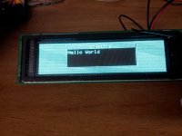
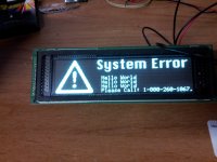
Trying to finish up the control console programming and design that will go to Apopka high school in florida, their new baseball scoreboard. My vintage mac nutness is starting to obstruct the design of my programming. LOL
Not to mention, I am in the process of starting to pack up and move.
Thought I'd post pictures of version 2.0 that I printed, though I've already started changes on it for version 3.0 to allow for the external ribbon cable.
As you can see for the SD card slot, I got the measurements wrong. I'll have to nudge it over. But not too shabby! I think I also need to add clips on the sides somewhere. Or maybe screw holes.
[attachment=2]1.JPG[/attachment]
[attachment=1]2.JPG[/attachment]
[attachment=0]3.JPG[/attachment]
As you can see for the SD card slot, I got the measurements wrong. I'll have to nudge it over. But not too shabby! I think I also need to add clips on the sides somewhere. Or maybe screw holes.
[attachment=2]1.JPG[/attachment]
[attachment=1]2.JPG[/attachment]
[attachment=0]3.JPG[/attachment]
I'm just going to print some round buttons that have a stick going down to the real buttons. I may make the button holes bigger, though, in version 3.0. I'm going to experiment with making some clips, as well, to clip the board down and the case. Right now both are connected via friction, which works fine, except if you were to drop it everything would go flying everywhere. Plus, the friction parts would ware out after a while, and it's stop holding together. Best to clip it down.
WOW just 299.00 what a deal!
http://printrbot.com/product-category/3d-printers/
[attachment=0]Screen shot 2014-01-08 at 2.11.29 PM.jpg[/attachment]
i had no idea they were this affordable!
http://printrbot.com/product-category/3d-printers/
[attachment=0]Screen shot 2014-01-08 at 2.11.29 PM.jpg[/attachment]
i had no idea they were this affordable!
:O
back on track: Very nice, oP! I've seen cases where the buttons/extenders are integrated into the injection molded part, I'll be on the lookout for one. I'm assuming that you're printing this face down, so it should be a piece of cake to do the springy/buttony/thingies.
Rapid prototyping makes it easy to do low-production parts which can't be done in the real world of injection molding, no release angle/access/multi-part tooling requirements. [}] ]'>
back on track: Very nice, oP! I've seen cases where the buttons/extenders are integrated into the injection molded part, I'll be on the lookout for one. I'm assuming that you're printing this face down, so it should be a piece of cake to do the springy/buttony/thingies.
Rapid prototyping makes it easy to do low-production parts which can't be done in the real world of injection molding, no release angle/access/multi-part tooling requirements. [}
] ]'>OK, here's 3.0. I changed the size a bit. This is now approximately 1/2 scale of an Apple 3.5" floppy drive.
I just realized as I'm writing this that I forgot the door for the cable extender, but it's now too late in the day. I'll fiddle with it tomorrow morning. Anyway, you'll get the idea. I added clips to keep the board in place, and some dimple thingies so the case will latch shut. You just press gently on the inseam to release, and the top case will pop off. Theoretically. I'll try printing it out tomorrow and give it a whirl. The large squares on the bottom are the same size as the inset squares on a floppy. So any of those classic Apple rectangle feets will stick in there.
[attachment=2]case.png[/attachment]
[attachment=1]clips.png[/attachment]
[attachment=0]buttons.png[/attachment]
I just realized as I'm writing this that I forgot the door for the cable extender, but it's now too late in the day. I'll fiddle with it tomorrow morning. Anyway, you'll get the idea. I added clips to keep the board in place, and some dimple thingies so the case will latch shut. You just press gently on the inseam to release, and the top case will pop off. Theoretically. I'll try printing it out tomorrow and give it a whirl. The large squares on the bottom are the same size as the inset squares on a floppy. So any of those classic Apple rectangle feets will stick in there.
[attachment=2]case.png[/attachment]
[attachment=1]clips.png[/attachment]
[attachment=0]buttons.png[/attachment]
Here're the case files:
http://olepigeon.trolans.net/case.zip
If anyone has a 3D printer, give it a whirl. I'm anxious to know if the bottom part of the case lines up and clicks together with the top. I'm so close to completing this, it's absolutely frustrating that the printer has decided to stop now. Probably even more frustrating for the tech teacher who has grades do at the end of the week, and no 3D printer for the kids to use.
Argh!

While the 3D printer is down, I'll be working on the spacers for the 2.5" drives. Unfortunately, I won't be able to test them until the printer is fixed. Sigh.
http://olepigeon.trolans.net/case.zip
If anyone has a 3D printer, give it a whirl. I'm anxious to know if the bottom part of the case lines up and clicks together with the top. I'm so close to completing this, it's absolutely frustrating that the printer has decided to stop now. Probably even more frustrating for the tech teacher who has grades do at the end of the week, and no 3D printer for the kids to use.
Argh!
While the 3D printer is down, I'll be working on the spacers for the 2.5" drives. Unfortunately, I won't be able to test them until the printer is fixed. Sigh.
Decided to call MakerBot instead of wait for an email (which, apparently, takes 24 hours.) They determined by the SN that we have an old plunger based extruder and are sending us a brand new spring based extruder. The old one can't maintain the tension to move the filament through, so it'll just stop and create a divot on the filament. They're sending us a new spring based extruder that should solve that problem.
Huzzah! Should be back and printing by the end of the week.
Huzzah! Should be back and printing by the end of the week.
What exactly is going wrong when you try to print the case? Sounds very frustrating.
I just unpacked my Printrbot Simple and printed the 5mm calibration cube successfully. The print quality seems mostly OK, though there are a couple of spots where it messed up and left little deformities or stray bits of plastic. Unfortunately the max print area of the Printrbot Simple is a few millimeters too small to print your case model.
I just unpacked my Printrbot Simple and printed the 5mm calibration cube successfully. The print quality seems mostly OK, though there are a couple of spots where it messed up and left little deformities or stray bits of plastic. Unfortunately the max print area of the Printrbot Simple is a few millimeters too small to print your case model.
As it gets higher and higher on the build, the part where it's trying to print is moving more and more as the build plate jitters. It then just fails because it's moving so much, the plastic can't adhere to itself. It starts off printing fine, then as it gets taller, it gets brittle and eventually doesn't print anything and just leaves a blob of plastic spaghetti.
It's cool having a two part case prototyped, but I think you might better to switch to a six part prototype of your prototype case before real frustration builds to the point of taking psychotic retributions upon school property. Been there, done that, but rarely upon the property of others. [}] ]'>
Maybe try doing dovetail joinery for the carcass sides held together with snap-on lid and bottom. :?:
@BMOW: some creative wood joinery would allow you to print a pair of ship-lapped parts that slide together, clicking into place with a latct for easy case removal. The overlapped sections bring the case down to dimensions that you can print.
] ]'>Maybe try doing dovetail joinery for the carcass sides held together with snap-on lid and bottom. :?:
@BMOW: some creative wood joinery would allow you to print a pair of ship-lapped parts that slide together, clicking into place with a latct for easy case removal. The overlapped sections bring the case down to dimensions that you can print.
So we're ordering a few more upgrades for our 3D printer. Talked to someone at a hackerspace, and all of their Replicators are having the same problem we are. They'll get about 50% up on a build and it starts to fall apart from vibration.
So we're ordering some aluminum arm upgrades that should help. The same company also makes a fancy heated build plate, so we might buy that, too.
In the meantime, I'm fiddling with my HDD adapter and riser. They're small and flat, so I should be able to print them even with the vibrations.
So we're ordering some aluminum arm upgrades that should help. The same company also makes a fancy heated build plate, so we might buy that, too.
In the meantime, I'm fiddling with my HDD adapter and riser. They're small and flat, so I should be able to print them even with the vibrations.
I think the whole filament/extruder hobby design needs re-thought out. It started with the makerbot I believe.
if the plastic was bonding correctly, and the part was adhered to the table, it should never fall apart. I think the types of filaments and temperature are key here..
if the plastic was bonding correctly, and the part was adhered to the table, it should never fall apart. I think the types of filaments and temperature are key here..
It sticks to the table fine, and the plastic bonds fine, as well. The problem is that the build plate vibrates. When it does that, the movement is compounded by the height of the object being printed. As it gets to about 1 1/2 to 2 inches above the build plate, it's vibrating enough that as the plastic melts and tries to adhere to the plastic below, the plastic below it is moving, preventing adhesion. It's like trying to glue two pieces of wood together that are constantly moving. It's not gonna work.
I've been printing a few prototype brackets and they're all coming out fine because they're flat pieces of plastic. The risers are only 1/2" tall, so they print fine too. Anything taller than that, then it gets more and more brittle as it gets taller, to the point where the print head is just moving around dropping a string of plastic as the whole build plate wobbles around.
I've been printing a few prototype brackets and they're all coming out fine because they're flat pieces of plastic. The risers are only 1/2" tall, so they print fine too. Anything taller than that, then it gets more and more brittle as it gets taller, to the point where the print head is just moving around dropping a string of plastic as the whole build plate wobbles around.