

Thread
Designing a portable RAM card
There's a store nearby and I think I can get a single 1.25 ghz daughter card from a MDD fairly cheap. I have a Dual 1.00 ghz MDD with a burnt out processor. I've googled and found articles going from a Single to Dualie but not the other way around. Anyone have an idea?
_________________
More macs than I can shake a stick at
_________________
More macs than I can shake a stick at
I decided to spin this off from my other thread. There seems to be some interest in this, so i decided to move on with the project.
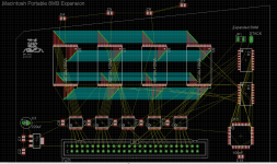
Here is my progress so far:
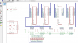
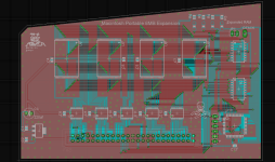
Still alot to go, but so far so good. Got the busses done, just need to get all the signal/enable/CPLD lines ran.
Turns out the apple guide to the family hardware is the correct one. the developer note is incorrect in pin numbering on the socket but the number to signal table figure appears right, and the designing cards and drivers for macintosh is completely wrong. pins and all.
Here is my progress so far:
Still alot to go, but so far so good. Got the busses done, just need to get all the signal/enable/CPLD lines ran.
Turns out the apple guide to the family hardware is the correct one. the developer note is incorrect in pin numbering on the socket but the number to signal table figure appears right, and the designing cards and drivers for macintosh is completely wrong. pins and all.
Yea, i bet that caused some havok for RAM card makers back in the day. lol.
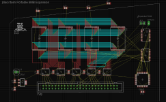
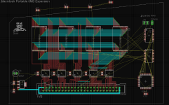
Anyway, more progress. Pretty much complete to operate as stock.
Just have to add a couple jumpers, extra connection points for the DTACK and /AS line for full 9MB extended addressing. Then of course i need to add the decoupling caps, and route the board.
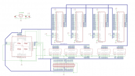
Anyway, more progress. Pretty much complete to operate as stock.
Just have to add a couple jumpers, extra connection points for the DTACK and /AS line for full 9MB extended addressing. Then of course i need to add the decoupling caps, and route the board.
Cool.
Generally, processor daughtercards designed for the same motherboards are interchangeable no matter the speed or CPU count. That was true as far back as the PCI-class Macs where you could swap dual processor cards for singles and vice versa. A few G4s in the Sawtooth era couldn't take a dual processor card in place of the stock single CPU because Apple firmware got in the way somehow. That's the only case I'm aware of where that general statement above doesn't hold true.
Peace,
Drew
_________________
Power to the PowerPC!
Generally, processor daughtercards designed for the same motherboards are interchangeable no matter the speed or CPU count. That was true as far back as the PCI-class Macs where you could swap dual processor cards for singles and vice versa. A few G4s in the Sawtooth era couldn't take a dual processor card in place of the stock single CPU because Apple firmware got in the way somehow. That's the only case I'm aware of where that general statement above doesn't hold true.
Peace,
Drew
_________________
Power to the PowerPC!
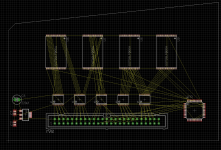
both. In theory, it should be universal.
the difference between the two models, the Backlit has a Refresh line, whilst the original does not. And the backlit /AS becomes /RAMCS, meaning its stuck at a 5MB ceiling, which is why I will have a pin to allow a wire to branch off to the next slot to pick up /AS for the full 9MB.
I will also have a DTACK pin as well, that will connect to the CPU DTACK line to allow the remaining 4MB of address space to be mapped to RAM without throwing bus errors.
In a nutshell, if you want all 9MB, you will have 2 plug-in wires coming of the board going to the ROM slot. or maybe PDS. If you dont want wires, your stuck at 5MB.
the difference between the two models, the Backlit has a Refresh line, whilst the original does not. And the backlit /AS becomes /RAMCS, meaning its stuck at a 5MB ceiling, which is why I will have a pin to allow a wire to branch off to the next slot to pick up /AS for the full 9MB.
I will also have a DTACK pin as well, that will connect to the CPU DTACK line to allow the remaining 4MB of address space to be mapped to RAM without throwing bus errors.
In a nutshell, if you want all 9MB, you will have 2 plug-in wires coming of the board going to the ROM slot. or maybe PDS. If you dont want wires, your stuck at 5MB.
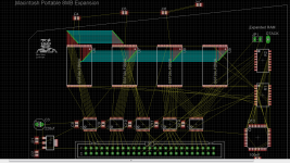

because as I mentioned before, two lines are switched and changed between the two models. the Backlit model has a Refresh signal, portable model does not.
Here is an apple doc explaining why:
http://24.52.155.15/dissport/Port_Dev_Blit.pdf
My setup, it should not matter.
Here is an apple doc explaining why:
http://24.52.155.15/dissport/Port_Dev_Blit.pdf
My setup, it should not matter.
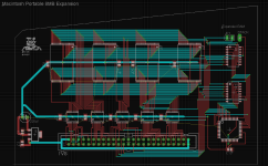

went ahead and asked for a quote for 5 pcs prototyping run, just to gauge an idea what each PCB is going to cost roughly. Then i get a bill of materials together, price of RAM from trag, and then assembly/test labor which at that point I can get a per piece price.
I make a poll to see whos interested in buying, so then I can justify the cost of running the boards.
of course, the PCBs might be cheaper if I order a larger number of them, or if I actually panelized the layout, but eh.. thats alot of work.
I make a poll to see whos interested in buying, so then I can justify the cost of running the boards.
of course, the PCBs might be cheaper if I order a larger number of them, or if I actually panelized the layout, but eh.. thats alot of work.
Yup, hopefully itll be cheap enough to hold interest. Otherwise i designed it all for nothing haha.
my next goal is to design an asyncronouse memory-mapped I/O PDS card.
So i can read/write specific addresses to read/write the card.
I dont really want to mess with DeclROMs, slot manager, slots, all that jaz that most cards do. Id rather just have simple peripheral cards that are directly addressed via drivers.
The next step toward a ARM co-processor/raspberry pi PDS card.
my next goal is to design an asyncronouse memory-mapped I/O PDS card.
So i can read/write specific addresses to read/write the card.
I dont really want to mess with DeclROMs, slot manager, slots, all that jaz that most cards do. Id rather just have simple peripheral cards that are directly addressed via drivers.
The next step toward a ARM co-processor/raspberry pi PDS card.
Well, I got quoted for 5 boards, at $62.50. This is basic green. different colors cost more.
$37 for the boards, and another 25 for shipping from china. sheesh. all the board houses are in china these days. Even imagineering is, which is who I used for our production boards for Major Display LLC.
$37 for the boards, and another 25 for shipping from china. sheesh. all the board houses are in china these days. Even imagineering is, which is who I used for our production boards for Major Display LLC.
Yeah, dealing with China can be expensive in shipping costs and shipping time (up to 6 weeks or more to go through customs? Sheesh!) But they are cheap otherwise.
TechKnight, copyright your design (send 2-self addressed mailed planes to yourself and open one up to see it and keep the other sealed until a "judge needs to see it," and keep both together) and then get an application to send a copy to the Copyright Office at the Library of Congress. Last time I had something copyrighted by the LoC was in the 1990s and cost $14, I don't know what it is now. I understand that you are doing this for the community and all, but its best to protect your ideas. It's nice to have that "by © year" with your name on it on what you put out.
TechKnight, copyright your design (send 2-self addressed mailed planes to yourself and open one up to see it and keep the other sealed until a "judge needs to see it," and keep both together) and then get an application to send a copy to the Copyright Office at the Library of Congress. Last time I had something copyrighted by the LoC was in the 1990s and cost $14, I don't know what it is now. I understand that you are doing this for the community and all, but its best to protect your ideas. It's nice to have that "by © year" with your name on it on what you put out.


I used to use ExpressPCB but I quit because its proprietary. Much easier than eagle though, but i rather use something that renders industry standard files.
plus expressPCB is very expensive.
I was using iTead with prototype runs, because it was cheap. but one of the guys split off and started his own thing, and i got a quote from him.
plus expressPCB is very expensive.
I was using iTead with prototype runs, because it was cheap. but one of the guys split off and started his own thing, and i got a quote from him.

Whoops. Almost royally screwed up. Got to make a design change.
These are 2MB chips. the on-board RAM is only 1 MB in size, and the decoding to external address space starts at 2MB. Problem is, the New RAM is 20 bits in size, while the original is a total of 19 bits in size. So, if I leave A19 of the toshiba RAM hooked into A20 of the original addressing space, that would kill off the first 1MB on my toshiba chip, basically wasting half the chip, as A20 would be high when moving into external addressing. Since A20 is routed to the toshiba chips, well yea....
So, I am going to have to break off A20 from the RAM. Leaving the RAM only accessing in 1MB chunks. Then, move A20 to the CPLD and do some 1-2 decoding to use the full address space.
Wow... good thing I caught that. Doing the CPLD work is what made me think of this.
This is precisely the reason that when using memory modules in computers, they all have to be "equal"
Elfin: Even if I did copyright it, whos got the money to hire a bunch of lawyers and court proceedings to fight an infringement? I dont, so who cares? Plus this is strictly a niche market with a small yield so it doesnt really matter.
These are 2MB chips. the on-board RAM is only 1 MB in size, and the decoding to external address space starts at 2MB. Problem is, the New RAM is 20 bits in size, while the original is a total of 19 bits in size. So, if I leave A19 of the toshiba RAM hooked into A20 of the original addressing space, that would kill off the first 1MB on my toshiba chip, basically wasting half the chip, as A20 would be high when moving into external addressing. Since A20 is routed to the toshiba chips, well yea....
So, I am going to have to break off A20 from the RAM. Leaving the RAM only accessing in 1MB chunks. Then, move A20 to the CPLD and do some 1-2 decoding to use the full address space.
Wow... good thing I caught that. Doing the CPLD work is what made me think of this.
This is precisely the reason that when using memory modules in computers, they all have to be "equal"
Elfin: Even if I did copyright it, whos got the money to hire a bunch of lawyers and court proceedings to fight an infringement? I dont, so who cares? Plus this is strictly a niche market with a small yield so it doesnt really matter.
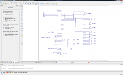
Here is my CPLD code in a nutshell:
Chip Select/Bank Select Signals.
A20, A21, A22, A23 Address line decode. The chip is hooked up between A0 and A18, or A1 to A19 if you look at the portable bus.
Base RAM:
0000 = No chip selected, all lines off = 0
Extended RAM:
0001 - Chip 1 Select ON, Lower Bank ON = 1
0010 = Chip 1 Select ON, Upper Bank ON = 2
0011 = Chip 2 Select ON, Lower Bank ON = 3
0100 = Chip 2 Select ON, Upper Bank ON = 4
0101 = Chip 3 Select ON, Lower Bank ON = 5
0110 = Chip 3 Select ON, Upper Bank ON = 6
0111 = Chip 4 Select ON, Lower Bank ON = 7
1000 = Chip 4 Select ON, Upper Bank ON = 8
When I say Upper/Lower bank, I mean just toggling A20 high or low. Since the macintosh portable has base RAM at 512K-Word, or 1MB, I decided to break the expansion down into 1 meg chunks as well. Since the toshiba chips are 1M-Word, or 2Mbytes, just deciding where A20 is determines if I am working with the first 512kword, or the second 512kword.
Chip Select/Bank Select Signals.
A20, A21, A22, A23 Address line decode. The chip is hooked up between A0 and A18, or A1 to A19 if you look at the portable bus.
Base RAM:
0000 = No chip selected, all lines off = 0
Extended RAM:
0001 - Chip 1 Select ON, Lower Bank ON = 1
0010 = Chip 1 Select ON, Upper Bank ON = 2
0011 = Chip 2 Select ON, Lower Bank ON = 3
0100 = Chip 2 Select ON, Upper Bank ON = 4
0101 = Chip 3 Select ON, Lower Bank ON = 5
0110 = Chip 3 Select ON, Upper Bank ON = 6
0111 = Chip 4 Select ON, Lower Bank ON = 7
1000 = Chip 4 Select ON, Upper Bank ON = 8
When I say Upper/Lower bank, I mean just toggling A20 high or low. Since the macintosh portable has base RAM at 512K-Word, or 1MB, I decided to break the expansion down into 1 meg chunks as well. Since the toshiba chips are 1M-Word, or 2Mbytes, just deciding where A20 is determines if I am working with the first 512kword, or the second 512kword.
By way of some special pass through connector in the ROM slot that breaks out the needed extra address lines? How will that be done, exactly? Or did you solve that by doing all the encoding/decoding/etc. on the card?
I will definitely be interested in one when it's ready.
...And a new back lit ribbon cable for the LCD (or a decent repair of the current one).
c
I will definitely be interested in one when it's ready.
...And a new back lit ribbon cable for the LCD (or a decent repair of the current one).
c
Techknight.... I don't know if this helps but I just found an 8MB PDS RAM card in my collection!!!!!!!! This gives you the full 8MB.. It's plugged into a 5126.. I don't know if there is more if you plug it in a 5120 but I will try... Look at the pics... It says Sunland Micro Systems
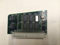
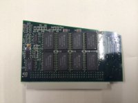
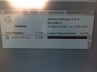
Matt
Matt
Well I did screw up. on one thing...
The boards did ship, and they shipped DHL. Unfortunately, they uncovered some big scandal at the ShenZhen dock, which is where my package is stuck at.
Something about counterfeit money and other stuffs, causing packages to be delayed up to a month or so before it leaves the dock via DHL.
I wish i would have known this prior to ordering and shipping via DHL...
The boards did ship, and they shipped DHL. Unfortunately, they uncovered some big scandal at the ShenZhen dock, which is where my package is stuck at.
Something about counterfeit money and other stuffs, causing packages to be delayed up to a month or so before it leaves the dock via DHL.
I wish i would have known this prior to ordering and shipping via DHL...
Doh! Bummer. With luck they'll get it sorted out quickly. They can't want to lose a bunch of commerce because of delays. Some time last year there was a big obstacle in shipping for remote control toy companies. Something about shipping lithium-poly batteries. They got it figured out eventually, but it took a while.
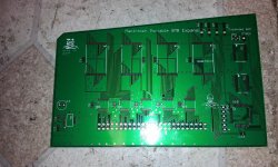
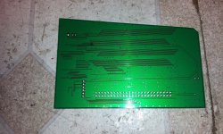
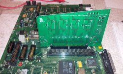
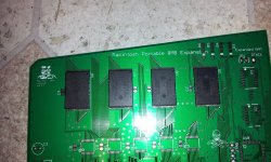
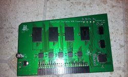
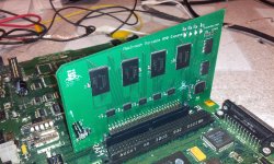
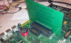
I did some more work on the CPLD code.
I removed all decoding logic except the very basic stuff, hooking up only the lower half of the first chip to the 4-to-16 decoder.
Tried it again, boom 2MB.
So... at least i know my board configuration is good! I didnt have any doubts about that. At least I got the hardware perfect right off the bat.
I removed all decoding logic except the very basic stuff, hooking up only the lower half of the first chip to the 4-to-16 decoder.
Tried it again, boom 2MB.
So... at least i know my board configuration is good! I didnt have any doubts about that.
At least I got the hardware perfect right off the bat. I found the problem. Not the solution yet...
Soon as I tie in the last MB of RAM, to take it up to 9MB is when it goes haywire. I'm thinking its running into ROM somehow. odd... As long as I stay at 8MB and under, it all works beautifully.
Soon as I add the last MB, spectacular failures
My original CPLD design is perfect. Just didnt like the last MB.
Soon as I tie in the last MB of RAM, to take it up to 9MB is when it goes haywire. I'm thinking its running into ROM somehow. odd... As long as I stay at 8MB and under, it all works beautifully.
Soon as I add the last MB, spectacular failures
My original CPLD design is perfect. Just didnt like the last MB.
Techknight.. from what I recall they could only go up to a certain size depending on the model.. I think the limit was 9 on one of them.. the other 8MB.. I remember seeing this.. Perhaps this is why my PDS was missing the last chip so it only had 8MB total.. and that was a card from a 5120.. I wish i could remember.. but the max was 8MB on one and 9 on the other..
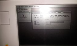
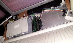
No jumper needed. its right at 8MB. I just turned off the last MB, so it stays at 8MB instead of 9MB. So basically we are wasting half of the last chip. doing nothing.
I could remap it in the expansion ROM area, but then we would need a special driver to tell the Mac OS to use it as RAM.
The last thing I need to do is toss it in a Backlit model and see if it works. In theory, it should be universal. I actually did NOT need the DTACK connection on the non-backlit. So, we will see on the Backlit whether I need it or not.
I could remap it in the expansion ROM area, but then we would need a special driver to tell the Mac OS to use it as RAM.
The last thing I need to do is toss it in a Backlit model and see if it works. In theory, it should be universal. I actually did NOT need the DTACK connection on the non-backlit. So, we will see on the Backlit whether I need it or not.
Found this...
NAME
MACINTOSH Portable M5126
MANUFACTURER
Apple
TYPE
Portable Computer
ORIGIN
U.S.A.
YEAR
1990
END OF PRODUCTION
1991
BUILT IN LANGUAGE
None
KEYBOARD
Typewriter style, 80-key with numeric keypad
CPU
Low power version of Motorola 68000
SPEED
16 MHz
RAM
1 MB (up to 9 MB)
ROM
256 KB
GRAPHIC MODES
640 x 400
COLORS
Monochrome
SOUND
8-bit stereo
SIZE / WEIGHT
33.8 x 37.7 x 10.3 cm / 7.1 kg
I/O PORTS
Serial, Parallel, SCSI, ADBx2
BUILT IN MEDIA
One 3.5'' FDD 40 MB HDD (optional)
OS
MAC OS 6.0.4 to 7.5.5
POWER SUPPLY
Internal lead-acid battery 6.5V
PRICE
$4200
NAME
MACINTOSH Portable M5126
MANUFACTURER
Apple
TYPE
Portable Computer
ORIGIN
U.S.A.
YEAR
1990
END OF PRODUCTION
1991
BUILT IN LANGUAGE
None
KEYBOARD
Typewriter style, 80-key with numeric keypad
CPU
Low power version of Motorola 68000
SPEED
16 MHz
RAM
1 MB (up to 9 MB)
ROM
256 KB
GRAPHIC MODES
640 x 400
COLORS
Monochrome
SOUND
8-bit stereo
SIZE / WEIGHT
33.8 x 37.7 x 10.3 cm / 7.1 kg
I/O PORTS
Serial, Parallel, SCSI, ADBx2
BUILT IN MEDIA
One 3.5'' FDD 40 MB HDD (optional)
OS
MAC OS 6.0.4 to 7.5.5
POWER SUPPLY
Internal lead-acid battery 6.5V
PRICE
$4200
That means I need two different CPLD firmwares. One for backlit, one for not...
Maybe the next PCB i need to add a jumper to enable/disable the 9th MB.
On my machine, that 9th MB will overlap ROM and she falls flat on its ass. lol.
I only ordered 5 PCBs on the first run to make sure I didnt have any hardware bugs. And I didnt, as I figured i wouldnt. I looked over that thing time and time again proofreading it.
New PCB will have the jumper. I need to see if the fab house has solder paste stencils. that will make things so much easier and faster. I did my first board all by hand.
Maybe the next PCB i need to add a jumper to enable/disable the 9th MB.
On my machine, that 9th MB will overlap ROM and she falls flat on its ass. lol.
I only ordered 5 PCBs on the first run to make sure I didnt have any hardware bugs. And I didnt, as I figured i wouldnt. I looked over that thing time and time again proofreading it.
New PCB will have the jumper. I need to see if the fab house has solder paste stencils. that will make things so much easier and faster. I did my first board all by hand.
The plot thickens, the Service Source also says there is a 9 MB ceiling:
http://tim.id.au/laptops/apple/legacy/macintosh_portable.pdf
http://tim.id.au/laptops/apple/legacy/macintosh_portable.pdf
Well, I know for a fact that the M5120 I have here on my desk, ROM starts at &H900000 which is the 9Megabyte marker. So yea I cant go past 9MB.
Unless I add the last MB of RAM to the ROM Expansion address location, but that would require a special extension to tell System 6/7 to use that as RAM. That is something I dont know how to do.
Unless I add the last MB of RAM to the ROM Expansion address location, but that would require a special extension to tell System 6/7 to use that as RAM. That is something I dont know how to do.
Backlit needs the /AS jumper. Without it it only sees 5MB. with it I can get all 8MB.
However there is an odd bug. When an application goes into expanded RAM the backlight flickers on and off rapidly with RAM accesses.
If I dont use the /AS wire and cap it at 5mb its perfectly fine.
But my /AS wire was a horrendously long clip lead plus I didnt have /DTACK hooked up either, so that could have been an issue.
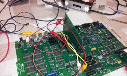
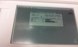
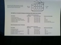
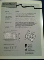
the /AS is the address strobe, yes...
Starting with the Backlit portable, they removed the /AS in the RAM connector and replaced it with a signal, known as /RAM.CS
This signal is controlled by an external address decoder network, which actually sits between the ROM socket, and the RAM itself. a series of 74 series gates. but I digress...
This /RAM.CS will only assert within the first 5MB of address space. After that, the signal no longer gets asserted. Therefore, on the M5126, you have a RAM ceiling of 5MB in the RAM slot. PDS is an exception though because you have access to the entire bus so these limitations dont exist.
but since I didnt feel like dealing with the Eurocard connectors, or the PDS, I designed the card to fit in the existing RAM slot.
So.... In order to gain full addressing on the backlit portable via the RAM slot, you have to pick off the /AS address strobe signal either from the PDS, or from the ROM slot. Since ROM is still attached directly to the bus, and not isolated through an external decoder.
The catch is, after 5+MB the RAM decoder network no longer generates a /DTACK signal to tell the processor that the data transfer was successful.
So, I am thinking that since I didnt hook the DTACK line up, it was causing a ton of bus errors even though the system information was showing the full 8MB of RAM.
If I use the /RAM.CS signal instead of /AS, everything works great. But only sees 5MB as expected. If I remove the jumper that connects to /RAM.CS and replace it with a wire that goes to /AS instead, It shows the full 8MB of RAM. But every time an application launches and uses the extended RAM (RAM past 1MB), the backlight flickers on and off extremely rapidly, at the same pace as the RAM accessing occurs.
so i think the DTACK connection not being made is an issue, OR, since my /AS wire clip lead was so long and coiled, it was distorting the signal to the RAM card causing issues with data transfers in and out of RAM.
Funny thing though... no bombs, or system errors/sad macs. Just kept right on chugging with backlight flickering. Soon as I exited microsoft word 5.1, it quit. backlight stayed on.
Starting with the Backlit portable, they removed the /AS in the RAM connector and replaced it with a signal, known as /RAM.CS
This signal is controlled by an external address decoder network, which actually sits between the ROM socket, and the RAM itself. a series of 74 series gates. but I digress...
This /RAM.CS will only assert within the first 5MB of address space. After that, the signal no longer gets asserted. Therefore, on the M5126, you have a RAM ceiling of 5MB in the RAM slot. PDS is an exception though because you have access to the entire bus so these limitations dont exist.
but since I didnt feel like dealing with the Eurocard connectors, or the PDS, I designed the card to fit in the existing RAM slot.
So.... In order to gain full addressing on the backlit portable via the RAM slot, you have to pick off the /AS address strobe signal either from the PDS, or from the ROM slot. Since ROM is still attached directly to the bus, and not isolated through an external decoder.
The catch is, after 5+MB the RAM decoder network no longer generates a /DTACK signal to tell the processor that the data transfer was successful.
So, I am thinking that since I didnt hook the DTACK line up, it was causing a ton of bus errors even though the system information was showing the full 8MB of RAM.
If I use the /RAM.CS signal instead of /AS, everything works great. But only sees 5MB as expected. If I remove the jumper that connects to /RAM.CS and replace it with a wire that goes to /AS instead, It shows the full 8MB of RAM. But every time an application launches and uses the extended RAM (RAM past 1MB), the backlight flickers on and off extremely rapidly, at the same pace as the RAM accessing occurs.
so i think the DTACK connection not being made is an issue, OR, since my /AS wire clip lead was so long and coiled, it was distorting the signal to the RAM card causing issues with data transfers in and out of RAM.
Funny thing though... no bombs, or system errors/sad macs. Just kept right on chugging with backlight flickering. Soon as I exited microsoft word 5.1, it quit. backlight stayed on.
you can try it, but i doubt itll work.
So what I did was setup 2 CPLD firmwares, one for 9MB, and one for 8MB. I built my 2nd card, and flashed it with 9MB.
But its giving me a chime loop so I think one of the RAM ICs trag sent is bad. my connections are ok.
So once I get that fixed, I can dick around and see if I can max the backlit model to 9MB. the non-backlit cannot exceed 8MB ever. unless ROM is moved.
Trying to do this without using the PDS slot, because my next goal is to attach a 68020 to the PDS.
So what I did was setup 2 CPLD firmwares, one for 9MB, and one for 8MB. I built my 2nd card, and flashed it with 9MB.
But its giving me a chime loop so I think one of the RAM ICs trag sent is bad. my connections are ok.
So once I get that fixed, I can dick around and see if I can max the backlit model to 9MB. the non-backlit cannot exceed 8MB ever. unless ROM is moved.
Trying to do this without using the PDS slot, because my next goal is to attach a 68020 to the PDS.
Soon as I learn how to do it.. cant find any reading materials out there for how to tie two processors together and busmaster them, which is how accelerators work.
Not to mention the bus incompatibilities. 68000 is a 16bit cpu with 16bit bus while 020+ is 32bit. So how do you run a 32 bit proc on a 16 bit bus? Im sure designers figured all this out 20+ years ago. But I havent.
Not to mention the bus incompatibilities. 68000 is a 16bit cpu with 16bit bus while 020+ is 32bit. So how do you run a 32 bit proc on a 16 bit bus? Im sure designers figured all this out 20+ years ago. But I havent.
I fixed my 2nd RAM card. One of the solder joints didnt take.
I ran the /AS line to the 2nd card on the backlit. Worked perfect no flickering.
My 1st card still flickered. Ironically this is the same card giving me problems in the non-backlit acessing 9MB. I think one of the RAM ics is bad.
Ill try my 2nd card tonight in the non backlit.
I ran the /AS line to the 2nd card on the backlit. Worked perfect no flickering.
My 1st card still flickered. Ironically this is the same card giving me problems in the non-backlit acessing 9MB. I think one of the RAM ics is bad.
Ill try my 2nd card tonight in the non backlit.
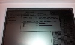
Replacing the RAM IC fixed it. So out of a handful from trag, only one was bad. Turns out I did not need DTACK so ill omit that in the next PCB revision.
Thats pretty good.
BTW. I only ordered 5 PCBs to make sure it all worked. First come first served.
Your looking at $75 per board for one without the LEDs. Or $80 if you want the LEDs for the cool factor.
I need to know how many are interested and qty so I can order all the correct parts.
Thats pretty good.
BTW. I only ordered 5 PCBs to make sure it all worked. First come first served.
Your looking at $75 per board for one without the LEDs. Or $80 if you want the LEDs for the cool factor.
I need to know how many are interested and qty so I can order all the correct parts.
Hmmm. That's a 1 out of 9 failure rate on the chips so far. That's not so good. I hope you just happened across the bad apple and that's not typical.
Have you tried running something like NewerTech's RAMometer memory test (also available in Guages) or some of the memory tests in TechToolPro? Check the chips bitwise...
Fabulously excellent work.
Hmmm, browsed the thread again, rereading your progress.
I also suggest you test RAM performance (RAMometer will give you a MB/S tested indicator) with and without your DTACK wire connected. Is it possible that without DTACK, the CPU is timing out and assuming the data is on the bus at some point, but that with DTACK, the transaction might complete several cycles sooner?
If there's some logical reason why the above paragraph is misdirected, feel free to ignore it.
Have you tried running something like NewerTech's RAMometer memory test (also available in Guages) or some of the memory tests in TechToolPro? Check the chips bitwise...
Fabulously excellent work.
Hmmm, browsed the thread again, rereading your progress.
I also suggest you test RAM performance (RAMometer will give you a MB/S tested indicator) with and without your DTACK wire connected. Is it possible that without DTACK, the CPU is timing out and assuming the data is on the bus at some point, but that with DTACK, the transaction might complete several cycles sooner?
If there's some logical reason why the above paragraph is misdirected, feel free to ignore it.
DTACK is generated automatically by the GLU. So i dont need to worry about it. The backlit portable has no wait states. So the speed is literally as fast as the RAM access time.
The non-backlit has wait states, I present the data available instantly, but the machine can only accept it within a certain amount of wait-states.
Its hard to say why the chip was bad. I could have killed it for all i know. I dont have any ESD matting or anything.
Also, do you have a link to any of those utilities?
The non-backlit has wait states, I present the data available instantly, but the machine can only accept it within a certain amount of wait-states.
Its hard to say why the chip was bad. I could have killed it for all i know. I dont have any ESD matting or anything.
Also, do you have a link to any of those utilities?
Now thats odd.
I got 9MB on haplains board, at the shop with my portable HDD.
Since I dont have an HDD solution yet on my non-backlit portable at home, I am booting off a 6.0.7 disk tools disk. Well same thing. Memory manager error and address error when using 9MB....
Do you have to have a full install of 6.0.7? or a system enabler I am not aware of?
I got 9MB on haplains board, at the shop with my portable HDD.
Since I dont have an HDD solution yet on my non-backlit portable at home, I am booting off a 6.0.7 disk tools disk. Well same thing. Memory manager error and address error when using 9MB....
Do you have to have a full install of 6.0.7? or a system enabler I am not aware of?
The Mac LC should be your inspiration because this is exactly what Apple did with it: The LC has a 16-bit bus and it's running a '020.
On the PC side of the fence Intel released the 386SX which was the low cost version of the 386DX. The 386DX had a full 32-bit external bus and the 386SX had a 16-bit external bus and fewer pins. The actual core of the two chips were effectively the same. (In the 1980s and early 1990s it was a lot more expensive to make a 32-bit system because your bus had to have many more traces.) I know that for Intel, they solved the problem by using 2 clock cycles to load a complete instruction. That is, every other clock cycle would either be the "high 16" or the "low 16."
Since the '020 doesn't have a shorter bus variant I do wonder how Apple made it work. At least we know it is possible to do.
Jumping the gun a bit here, but, if these sell very fast, and you run out of SRAM chips, Mouser has this chip (263 in stock):
http://www.mouser.com/ProductDetail/Alliance-Memory/AS6C1616-55TIN/?qs=sGAEpiMZZMt9mBA6nIyysDfDw0vDQxSw%2fJdd2EqgHt0%3d
It would be about $7 each if you bought 100 of them, but they have the same pinout as the TC55BVM416, are TTL compatible and are in the same package. Probably bump the cost of the card up from $75 to $100, but at least you'd be able to make more of them using the same PCB.
The only issue I see is that the AS6C1616 does not support X8 mode. Only 1M X 16. I'm still not clear on whether you're using the TC55BVM416 in 1M X 16 mode or in pairs as 2M X 8.
http://www.mouser.com/ProductDetail/Alliance-Memory/AS6C1616-55TIN/?qs=sGAEpiMZZMt9mBA6nIyysDfDw0vDQxSw%2fJdd2EqgHt0%3d
It would be about $7 each if you bought 100 of them, but they have the same pinout as the TC55BVM416, are TTL compatible and are in the same package. Probably bump the cost of the card up from $75 to $100, but at least you'd be able to make more of them using the same PCB.
The only issue I see is that the AS6C1616 does not support X8 mode. Only 1M X 16. I'm still not clear on whether you're using the TC55BVM416 in 1M X 16 mode or in pairs as 2M X 8.
http://maben.homeip.net/static/S100/motorola/68020/Motorola%20ANE%20001D%20application%20note.pdf
Is that what you are looking for?
Nope. I need the AN994/D.
Closest I come was a post in the Freescale forum, but the attachment is long gone.
Scavenging around with that search, I found an amiga 68020 accelerator, and its associated PAL code in a document from the 80s. This document also refers to that same application note, which is how it hit on the search engine.
Problem is, I dont understand CUPL so i dont know how to convert CUPL into discrete logic.
But from what I gather so far, attaching a 68020 to the system bus, might as well go with 030, little difference. Seems relatively streight foward.
Just have to have the logic to break it down to 16 bit cycles, and then you need the Syncronous generation logic becuase its missing in the 020. Basically the E, VPA, etc.. signals.
Then the bus mastering logic.
As long as we have these 3 logic blocks, everything else pretty much just works. The Amiga they were converting the 7Mhz bus signal to the async 16Mhz so the guy had to create a whole bunch of extra logic to keep DSACK happy, and other things happy. Whereas in my case, the bus is already at 16Mhz, and I will keep the same for the CPU. So i can cut out that extra logic.
Closest I come was a post in the Freescale forum, but the attachment is long gone.
Scavenging around with that search, I found an amiga 68020 accelerator, and its associated PAL code in a document from the 80s. This document also refers to that same application note, which is how it hit on the search engine.
Problem is, I dont understand CUPL so i dont know how to convert CUPL into discrete logic.
But from what I gather so far, attaching a 68020 to the system bus, might as well go with 030, little difference. Seems relatively streight foward.
Just have to have the logic to break it down to 16 bit cycles, and then you need the Syncronous generation logic becuase its missing in the 020. Basically the E, VPA, etc.. signals.
Then the bus mastering logic.
As long as we have these 3 logic blocks, everything else pretty much just works. The Amiga they were converting the 7Mhz bus signal to the async 16Mhz so the guy had to create a whole bunch of extra logic to keep DSACK happy, and other things happy. Whereas in my case, the bus is already at 16Mhz, and I will keep the same for the CPU. So i can cut out that extra logic.
Is there a reason you want to go with the 68020 instead of the '030 specifically?
The 68030 user manual goes into pretty extensive depth about how the bus sizing mechanism works. The manual includes some example PAL equations for the byte select logic needed for smaller bus sizes, which I think is pretty much what you'd get out of that application note. There are some minor differences in how the bus sizing works for the 68020 (said differences are mentioned in the manual) but you may be able to use the hardware design mostly unchanged anyway.
(EDIT: Downloaded and skimmed the '020 manual and it looks like it has the same material in it. You might want to sign up to the Motorola support forum and ask for the app note there. Google points to a discussion there where someone found it and gave it to someone else via an attachment, but the attachment doesn't seem to be available anymore, at least without a login.)
EDIT again: I assume you found this PDF already, about interfacing a 68020 to an Amiga?
The 68030 user manual goes into pretty extensive depth about how the bus sizing mechanism works. The manual includes some example PAL equations for the byte select logic needed for smaller bus sizes, which I think is pretty much what you'd get out of that application note. There are some minor differences in how the bus sizing works for the 68020 (said differences are mentioned in the manual) but you may be able to use the hardware design mostly unchanged anyway.
(EDIT: Downloaded and skimmed the '020 manual and it looks like it has the same material in it. You might want to sign up to the Motorola support forum and ask for the app note there. Google points to a discussion there where someone found it and gave it to someone else via an attachment, but the attachment doesn't seem to be available anymore, at least without a login.)
EDIT again: I assume you found this PDF already, about interfacing a 68020 to an Amiga?
Doubt it. The 170 is 32-bit throughout.
Best I can do is LC. As itll be 32 bit shoehorned on a 16 bit bus.. however... there is a however.
I can fill the rest of the new address space as RAM, 32 Bit RAM.
Then if I can figure out how to tell Mac os to use the RAM at the end of address space instead of the beginning, it should increase the performance immensely.
Nothing I can do about exception and interrupt vectors which reside on low ram. But eh. Just got to tell the mac memory manager where "ram" is.
Im sure itll be some sort of extension or system enabler coded to do it. Leave interrupts and exception in low ram. Move heaps and system into high ram.
Bbraun would know more than I about this part.
Best I can do is LC. As itll be 32 bit shoehorned on a 16 bit bus.. however... there is a however.
I can fill the rest of the new address space as RAM, 32 Bit RAM.
Then if I can figure out how to tell Mac os to use the RAM at the end of address space instead of the beginning, it should increase the performance immensely.
Nothing I can do about exception and interrupt vectors which reside on low ram. But eh. Just got to tell the mac memory manager where "ram" is.
Im sure itll be some sort of extension or system enabler coded to do it. Leave interrupts and exception in low ram. Move heaps and system into high ram.
Bbraun would know more than I about this part.
68020 and greater Macs need a hardware widget to remap their RAM into a contiguous block (be that the special stripped-down remapping chip in the Mac II, the version of that built into the LC, or the onboard MMU in the '030 and later systems.) and the memory maps for the two modes are substantially different. (I/O gets shoved to the top of the 32 bit address space, etc.) This is why even "real" Mac II family systems can't use more than 8MB of RAM in 24 bit addressing mode, and why accelerators for 16 bit Macs that include onboard RAM sockets are generally limited to using anything above the 4MB mark for RAMdisks, etc.
I do recall reading about some software for Mac II's with full MMUs that would let you get up to 14MB of RAM in System 6 by doing some really, really horrible things; IE, copying the MacOS ROM up to RAM destined to be mapped at the 15MB mark, patching it so it worked there, and using the MMU to map RAM on top of the 24 bit address spaces for the NuBus slots. (I believe to use this software you actually had to rearrange your NuBus cards so they counted down from the top slot, and each card you used knocked 1MB off the maximum RAM you could have.) In principle I suppose you could do something akin to that and relocate the Portable's ROMs upward, but you'll still need an MMU.
(Edit: Someone undoubtedly knows what this software is; again, I read about it *ages* ago and am undoubtedly misremembering details.)
Virtual Compact from Connectix created a RAM disk, then assigned the Virtual Memory to the RAM disk. It's a feature they took out of RAM Doubler, which would have been really nice. There's no option to set which disk as the source for virtual memory, Virtual Compact is the only software I know that does that.
I stumbled across an Apple KB article that mentions the software I was thinking of: "Connectix Maxima". I gather from related googling that it didn't actually relocate the ROM, it stayed at the 8MB mark, but, depending on how many Nubus cards you had, gave you a second block of up to 6MB of RAM, with the proviso that a single program couldn't use more than 8MB-minus-system-overhead. (You could, for instance, load Photoshop or something into the bottom 8MB with a maximum allocation and then use the multifinder to load some smaller programs into the extended space you'd carved out.)
The fact that this exists does suggest that mapping another, say, 4MB onto a PDS card and using it to run MOAR programs might just be feasable. (Since unlike the compact Macs the Portable actually crams its I/O into a compact space, instead of smearing it all over the top half of the address bus.) You'll need something like a patched version of Maxima to do it, and I'd still say there's likely to be formidable problems with going over the 16MB mark for anything but a RAMdisk. (Unless miraculously the Portable's ROMs are 32-bit clean, as would have to be any software you'd like to run.) If you're *really* dreaming big I suppose you could talk about going with a 68030 (you'll need the MMU) and soft-loading a custom Mac II-caliber ROM, essentially converting the Portable into a PB140-class machine when the accelerator is enabled. I'm sure grafting the drivers from the Portable's ROM into a 32 bit clean ROM image is something BBraun could do over a long weekend. Go for it!
The fact that this exists does suggest that mapping another, say, 4MB onto a PDS card and using it to run MOAR programs might just be feasable. (Since unlike the compact Macs the Portable actually crams its I/O into a compact space, instead of smearing it all over the top half of the address bus.) You'll need something like a patched version of Maxima to do it, and I'd still say there's likely to be formidable problems with going over the 16MB mark for anything but a RAMdisk. (Unless miraculously the Portable's ROMs are 32-bit clean, as would have to be any software you'd like to run.) If you're *really* dreaming big I suppose you could talk about going with a 68030 (you'll need the MMU) and soft-loading a custom Mac II-caliber ROM, essentially converting the Portable into a PB140-class machine when the accelerator is enabled. I'm sure grafting the drivers from the Portable's ROM into a 32 bit clean ROM image is something BBraun could do over a long weekend. Go for it!
Yea, i thought about adding 32-bit RAM past the end of the 16MB bus. Problem is, the ROM obviously isnt 32-bit clean so i dunno how well it would handle a number past 16MB, it obviously wouldnt. So even if I did patch the OS with an extension to include RAM located past the 24-bit address space.
it would probably barf.
the Portable's ROM is the macintosh SE rom with portable specific addressing and drivers. Such as the .Backlight, etc..
I guess another idea is just like what was mentioned before, Add a GB of RAM, and use it only for a RAM Disk, put a coin cell battery on it so technically it becomes a "pseudo-physical" disk at that point. So in theory, what we have here is an SSD.
But eh now we are getting all convoluted.
First things first, get the RAM boards produced and sold. Right now there really doesnt seem to be a whole lot of interest in the RAM, but I havent extended the market to ebay either.
Once those are sold, i will start work on the 020/030. Start off simple. clock doubled CPU/FPU only for now.
it would probably barf.
the Portable's ROM is the macintosh SE rom with portable specific addressing and drivers. Such as the .Backlight, etc..
I guess another idea is just like what was mentioned before, Add a GB of RAM, and use it only for a RAM Disk, put a coin cell battery on it so technically it becomes a "pseudo-physical" disk at that point. So in theory, what we have here is an SSD.
But eh now we are getting all convoluted.
First things first, get the RAM boards produced and sold. Right now there really doesnt seem to be a whole lot of interest in the RAM, but I havent extended the market to ebay either.
Once those are sold, i will start work on the 020/030. Start off simple. clock doubled CPU/FPU only for now.
I think its as good as its going to get, I decided to fill the entire RAM as a RAM disk, outside of 2MB. so 7MB RAM disk. and installed system 7.1 onto the RAM disk.
running perfect, and its keeping on power-off so that means at least I designed the RAM card properly, and its booting system 7.1 really fast off RAM.
running perfect, and its keeping on power-off so that means at least I designed the RAM card properly, and its booting system 7.1 really fast off RAM.
Does the Portable assert that Standby signal that you mentioned? It may not be worth the power savings, but the SRAM can maintain contents on 1V or something like that (mentioned in the datasheet). It would require another voltage regulator and a three more CPLD pins and maybe a couple of switching transistors, but you could set the thing up to supply 1V to the RAM when the Standby signal is asserted. That would reduce the power consumption while the machine is off. Might also need a largish capacitor to smooth over the transition between power supplies.
Suspected that might be the case. SRAM really uses tiny amounts of power. Still, can't help thinking of unnecessary "optimizations".
Also, not sure if running them on a 1V Vreg would save much power even if the chips used more current. Since simple Vregs lower the voltage in part by dissipating power resistively to get to a lower voltage, switching from 3.3V to 1V might just move the power consumption from the SRAM chips to the 1V voltage regulator.
This Portable Ram Max out card is awesome... i want one for my 2 portables.
My 5120 and 5126.
the 5120 already has a stock 1meg ram card in it. The 5126 has no ram expansion only one meg ram onboard.
i need at least 2 megs of ram to run 7.1, ( pretty much my favorite OS )
So i will move on one Ram Card, $80 bucks as soon as i get the cash. And i don't mind getting a little cash back in circulation with mike
Getting him some R&D moneys paid back.
My 5120 and 5126.
the 5120 already has a stock 1meg ram card in it. The 5126 has no ram expansion only one meg ram onboard.
i need at least 2 megs of ram to run 7.1, ( pretty much my favorite OS )
So i will move on one Ram Card, $80 bucks as soon as i get the cash. And i don't mind getting a little cash back in circulation with mike
Getting him some R&D moneys paid back.
Did you ever solve this? Backlight flickering when you access memory above 5MB? I would doubt that the lack of a /DTACK signal has anything to do with it - if the CPU needed /DTACK but it wasn't present, it should just freeze up, or else there might be some external logic that forces a bus error. Either way I think you'd see major software problems, not just a flickering backlight.
My guess is you may have bus contention. Something else is mapped into the memory region above 5MB, and now your RAM card and that something else are trying to drive the bus at the same time. This causes a sudden increase in the power supply current, making the supply voltage droop, and causing the backlight to visibly flicker. The only problem with my theory is that if you had bus contention, you should also also see noise/bad data on the bus, leading to software errors. Maybe the new RAM chips just have more powerful drivers, and overwhelm whatever other thing they're fighting with.
Very nice work!
it was a bad RAM IC. I swapped the RAM, and all is well.... This same card was giving me weird issues as well on the non-backlit, memory manager errors when going to about this macintosh.
But the Backlit is capped at 8MB, while the non-backlit is at 9MB. My guess is the last MB of RAM is occupied by the backlight controller.
Replacing the RAM IC fixed it all. My new PCBs will have a 7MB cap jumper. to disable the last meg of RAM for the backlit portable, if it becomes an issue.
But the Backlit is capped at 8MB, while the non-backlit is at 9MB. My guess is the last MB of RAM is occupied by the backlight controller.
Replacing the RAM IC fixed it all. My new PCBs will have a 7MB cap jumper. to disable the last meg of RAM for the backlit portable, if it becomes an issue.
I bought one of these off ebay! Thanks! It works great! My 5120 has been entirely recapped by a genius at the soldering gun, waiting on a cable to mount the scsi2sd, with the 8 megs of ram, and working on a new battery solution. I hate the Macintosh (in general) but this baby is just .. way, way too cute. And it looks nice next to the IIc+.
Only thing is, system 608 crashes when trying to access "About the Finder". I got worried for a minute after I installed the card, but after booting 701 and 71 and seeing the entire 9 megabytes the problem definitely lies within system 6. Is it just a case of "There's no way a portable can have 9 megs of ram, I shall now crash the Memory Manager" (rhetorical question I guess, as I won't be running 6 anymore)
My 5120 has been entirely recapped by a genius at the soldering gun, waiting on a cable to mount the scsi2sd, with the 8 megs of ram, and working on a new battery solution. I hate the Macintosh (in general) but this baby is just .. way, way too cute. And it looks nice next to the IIc+.Only thing is, system 608 crashes when trying to access "About the Finder". I got worried for a minute after I installed the card, but after booting 701 and 71 and seeing the entire 9 megabytes the problem definitely lies within system 6. Is it just a case of "There's no way a portable can have 9 megs of ram, I shall now crash the Memory Manager" (rhetorical question I guess, as I won't be running 6 anymore)
Run it without the memory expansion and set the memory control panel and then boot with extensions off. I'm sure there is something in the extensions causing problems.
Then install the memory expansion back in and see if the boots with extensions off and then extensions on.
Then install the memory expansion back in and see if the boots with extensions off and then extensions on.
If you had a version of Virtual Compact that run on Portables (maybe it's hackable?), you could stuff as much RAM on that thing as physically possible. All the extra RAM-as-RAMdisk would then become virtual memory storage. So there'd be almost no hit on performance, and you'd have a butt load of RAM.
Yea, well it happens. The problem with all the testing software is they either run full 32-bit addressing, or at the minimum require CFM-68K which again requires an 020+ one of the biggest reasons I want the 020/030 running in my portable.
Seems the best way for me to test is just create a 100% RAM disk to utilize maximum RAM, copy all my HDD contents over and boot from RAM. if everything is ok without bombing out there there, then its a good bet that the RAM is ok.
So far out of the 12 I just assembled, I have 1 that has another bad RAM IC.
Seems the best way for me to test is just create a 100% RAM disk to utilize maximum RAM, copy all my HDD contents over and boot from RAM. if everything is ok without bombing out there there, then its a good bet that the RAM is ok.
So far out of the 12 I just assembled, I have 1 that has another bad RAM IC.