

Thread
Another IIci ROM hack
It's probably the capacitors on the 'dead' IIci board. I bet they were ready to go and you've been using it more than usual. The soft power circuit is fairly simple, totally separate from any ROM-related stuff, and a schematic can be found on Gamba's site:

As you can see, even if you blew up the processor, the soft power would still kick on the power supply, so the problem is somewhere on this schematic, most likely the electrolytic capacitors. I'm actually surprised if ANY IIci still works with stock capacitors after this long. None of mine did.
As you can see, even if you blew up the processor, the soft power would still kick on the power supply, so the problem is somewhere on this schematic, most likely the electrolytic capacitors. I'm actually surprised if ANY IIci still works with stock capacitors after this long. None of mine did.
Cool! And as for how you did the ASC stuff, awesome! I started looking at the Sound Manager drivers a little bit, but the MESS code was so much simpler to follow. I think I found an interesting string resource in the System file describing the ASC driver, I might have to pull that one out if I can find it again.Got the Quadra 700 to boot into Finder in MESS this weekend after a few months of hitting my head against various aspects, but there's always more work to do
Haha, good point! That has to be what happenedI think it died from too much awesomeness.
Thanks for the suggestion jt! Unfortunately that same power cord booted the other IIci fine. Oh man that would be annoying to discover that the power cord was the problem all along
Yeah, it was pretty surprising it was still working. I haven't checked to see if there are leaking caps but there must be. In fact I think this machine was having some kind of weird problem where soft power down would result in an immediate reboot, but that problem mysteriously disappeared. I'll take a look at it later, thank you for the info!
Do you happen to have any ideas on repairing a IIci power supply? My other machine has an Astec power supply that bit the dust, so they are both sharing this GE one. I saw the diode fix and haven't been able to try it, but the "flip a power strip off and on" trick wouldn't work for me and I'm not getting a 5V trickle voltage out of it at all.
My IIci worked fine for the past few years. I didn't even think to check for leaky caps until recently. I then recapped my IIci. Still works great. Now all I need is a Quadra 700 power supply to replace the one in my IIci. I don't think the original power supply has enough power to run my accelerator. 
LOL, I definitely need to re-cap and clean that "bad" logic board. I noticed the board is filthy near the soft power circuit (underneath the power supply), some from dust and some from leaky caps. I blew compressed air all over the soft power circuit and the IIci is alive again. OK for a temporary fix but I will re-cap and clean it soon.
Thanks again for the info Dennis Nedry! When you said that it would still at least start the power supply if I had blown the CPU for example, that made me feel a lot better!
Thanks again for the info Dennis Nedry! When you said that it would still at least start the power supply if I had blown the CPU for example, that made me feel a lot better!
No problem Doug! I've never found any exact science with power supplies. If you find clues on the web, definitely try those first. Otherwise if you're really lucky you might find a big chunk out of something or a bulged out capacitor, but most of the time there won't be a visible sign. In that case, I guess I'd start by pulling out a voltmeter and trying to trace back from the trickle line until I found some juice.
I have fixed a couple of IIsi power supplies that had two smallish electrolytics that went bad with no visible signs. They shorted the trickle to ground I believe. When poking around, it helps to think about, what should this voltage be at this point, and what would make it wrong. Is there a series resistor behind this point, if so, test both sides of it. If it's good on one side and not the other, poke around the bad side for things that could be shorting it. Just basic experimentation like that, unsolder things, test if possible, solder on similar parts if you can't test, etc. Knowledge to gain and not much to lose.
You can even take a pretty good bet a lot of times and unsolder all of the capacitors one by one, testing for a short. If they don't test as shorted, maybe they're blown open, but that's not usually likely to make a power supply totally dead.
Heck, try plugging AC into the power supply just out on its own and feeding it external +5V to pin 9, ground to 5, 6, or 7, defeating the purpose of the trickle voltage. Whatever happens or doesn't happen could give you some clues. Maybe it's just the trickle, maybe it's deeper if it still doesn't wake up.
I have fixed a couple of IIsi power supplies that had two smallish electrolytics that went bad with no visible signs. They shorted the trickle to ground I believe. When poking around, it helps to think about, what should this voltage be at this point, and what would make it wrong. Is there a series resistor behind this point, if so, test both sides of it. If it's good on one side and not the other, poke around the bad side for things that could be shorting it. Just basic experimentation like that, unsolder things, test if possible, solder on similar parts if you can't test, etc. Knowledge to gain and not much to lose.
You can even take a pretty good bet a lot of times and unsolder all of the capacitors one by one, testing for a short. If they don't test as shorted, maybe they're blown open, but that's not usually likely to make a power supply totally dead.
Heck, try plugging AC into the power supply just out on its own and feeding it external +5V to pin 9, ground to 5, 6, or 7, defeating the purpose of the trickle voltage. Whatever happens or doesn't happen could give you some clues. Maybe it's just the trickle, maybe it's deeper if it still doesn't wake up.
Thanks for all the info Dennis Nedry! I tried your last suggestion since it didn't involve any case opening and...whoa...
So I applied +5V from my bench PSU to the /PFW pin (9) (and connected the grounds together), as you suggested.
I heard a relay click and the fan started spinning slower than usual. I measured the outputs and they were jumping wildly from where they are supposed to be (12V was jumping between 6 to 8 V, -12V was jumping between -6V to -8V, and 5V was jumping between 0 and 4V). It was drawing about 30 mA from my bench supply.
Then, I removed my bench supply and started playing around looking at the pins. I checked the +5V trickle pin (10), and the +5V trickle was there again! I didn't bother checking before I had started playing around with it though, so it's possible the trickle was already there, but I know at one point a while ago it was completely gone. So I tried telling the power supply to turn itself on by shorting /PFW and the +5V trickle, and it did the same thing it does with external power -- slow fan and too-low voltages.
Anyway, naturally after seeing that, I put the power supply into my other IIci, and suddenly, IT WORKS!
WTF is going on here? Did applying external power "fix" the +5V trickle temporarily or something? Did I accidentally make a loose solder joint good again by moving it around? Why does jump-starting the power supply like I did not allow the voltages to go all the way up? This is confusing and exciting because both my power supplies work again! Thanks for the awesome suggestions! I still have no idea what is going on here...haha
So I applied +5V from my bench PSU to the /PFW pin (9) (and connected the grounds together), as you suggested.
I heard a relay click and the fan started spinning slower than usual. I measured the outputs and they were jumping wildly from where they are supposed to be (12V was jumping between 6 to 8 V, -12V was jumping between -6V to -8V, and 5V was jumping between 0 and 4V). It was drawing about 30 mA from my bench supply.
Then, I removed my bench supply and started playing around looking at the pins. I checked the +5V trickle pin (10), and the +5V trickle was there again! I didn't bother checking before I had started playing around with it though, so it's possible the trickle was already there, but I know at one point a while ago it was completely gone. So I tried telling the power supply to turn itself on by shorting /PFW and the +5V trickle, and it did the same thing it does with external power -- slow fan and too-low voltages.
Anyway, naturally after seeing that, I put the power supply into my other IIci, and suddenly, IT WORKS!
WTF is going on here? Did applying external power "fix" the +5V trickle temporarily or something? Did I accidentally make a loose solder joint good again by moving it around? Why does jump-starting the power supply like I did not allow the voltages to go all the way up? This is confusing and exciting because both my power supplies work again! Thanks for the awesome suggestions! I still have no idea what is going on here...haha
The computer gods are pleased with your work, and rewarded you with a working power supply.  )
)
)
Woah. Having finally taken the time to read and comprehend this thread properly, all I can say is -
What an epic adventure - and by the sound of it, this is just the beginning. dougg3, and everyone involved, take a bow.
What an epic adventure - and by the sound of it, this is just the beginning. dougg3, and everyone involved, take a bow.
So, to check that I'm up to speed-
I gather that the barrier to using the ROM slot as storage or general-purpose expansion is the absence of any write lines?
Also, Trash, it's worth bearing in mind that a USB *Device* port/chipset/stack and a USB *Host* port are not the same thing. The one on a computer is a host, the one on a disk is a device. There is a protocol that can do both, called USB On The Go (OTG) - but in general, an IC that acts as a device will not be able to mount (host) another device. Pardon me if I'm pointing out the bleedin' obvious here, but from your earlier posts, you seemed to be making that confusion.
Meanwhile, this tidbit caught my eye, and perhaps warrants further investigation:
*cough* SD card?
One small suggestion for the programming board- USB to RS232 or TTL cables are readily available, cheap, and infinitely useful for further hackery, so, in order to keep the custom board as simple (ergo, cheap) as possible, why not have TTL or serial headers on the board, and let the end user buy a USB converter? Some of us will no doubt have one lying about, and others (like me) have been meaning to get one anyway.
That also leaves the door open for maniacs who might want to program their ROM from a Mac serial port
I gather that the barrier to using the ROM slot as storage or general-purpose expansion is the absence of any write lines?
Also, Trash, it's worth bearing in mind that a USB *Device* port/chipset/stack and a USB *Host* port are not the same thing. The one on a computer is a host, the one on a disk is a device. There is a protocol that can do both, called USB On The Go (OTG) - but in general, an IC that acts as a device will not be able to mount (host) another device. Pardon me if I'm pointing out the bleedin' obvious here, but from your earlier posts, you seemed to be making that confusion.
Meanwhile, this tidbit caught my eye, and perhaps warrants further investigation:
Sure, still read-only, but perhaps a convenient, OS-friendly way of making use of spare ROM capacity?
*cough* SD card?
One small suggestion for the programming board- USB to RS232 or TTL cables are readily available, cheap, and infinitely useful for further hackery, so, in order to keep the custom board as simple (ergo, cheap) as possible, why not have TTL or serial headers on the board, and let the end user buy a USB converter? Some of us will no doubt have one lying about, and others (like me) have been meaning to get one anyway.
That also leaves the door open for maniacs who might want to program their ROM from a Mac serial port
I'm glad to hear that your power supply is working. Have you tested the voltages on the logic board with this power supply running? You can test +5 and +12 easily in the hard drive power connector. I'm a little bit concerned that the voltages were unstable.
Well if your voltages are "bouncing" that means the power supply is cycling, which means there is an overload on one of the rails somewhere. Unplug the power supply from the mainboard, measure each rail point to ground in ohms. take a note of the measurements. Go to a good board, do the same thing. what you will likely find is one or more of the rails is reading lower resistance = leakage/short somewhere. have to track it down.
That's about the only explanation that makes any sense! ;-)The computer gods are pleased with your work, and rewarded you with a working power supply.
Thank Bunsen! I still appreciate all the info/feedback/help everyone has given me on this project, it has been a TON of fun even through the few minor roadblocks I keep running into! It's also helping me get into hardware stuff which has always been fascinating to me.
Exactly -- I suppose we could tie into a write enable line somewhere (maybe?) and get read/write capabilities, but I don't know where to look for that or if it's even feasible -- maybe someone with more hardware knowledge would know?
As long as a microcontroller/FPGA or something could translate between ROM requests and SD card accesses, but the fast timing there would probably cause problems. BMOW probably knows more about this stuff and I'm suspecting that the image of what's stored on the SD card would have to be loaded into RAM that's connected to the IIci's SIMM pins--I don't think it could read off the SD card in real time fast enough (at least that's my first guess).
Good idea! It also makes the board design easier for meOne small suggestion for the programming board- USB to RS232 or TTL cables are readily available, cheap, and infinitely useful for further hackery, so, in order to keep the custom board as simple (ergo, cheap) as possible, why not have TTL or serial headers on the board, and let the end user buy a USB converter? Some of us will no doubt have one lying about, and others (like me) have been meaning to get one anyway.
That also leaves the door open for maniacs who might want to program their ROM from a Mac serial port
Since I'm going to be using a 5V microcontroller, it would be easier if I use a 5V serial port instead of 3.3V. Is that going to cause a problem? I think a lot of those types of cables are designed for 3.3V if I'm not mistaken.Me too
I just did that...thanks for the idea.+5V reads as 5.10 V
+12V reads as 11.89 V
-12V reads as -12.18 V
Those seem ok...maybe the IIci power supply doesn't like to be started without a load connected to it?
Thanks for the info techknight! The weird thing is that the power supply was doing that outside of the computer with no motherboard connected to it. With a motherboard connected to it, it behaves fine. Could starting the power supply with no load cause it to choke like that and keep cycling?
SIMM Update:
The second SIMM I have been having trouble with is now functional. It had nothing to do with the solder paste -- again, it was a case of nearby SIMM contacts getting shorted to each other. Possibly this time by me scraping the contacts with my probe as I was testing continuity. Something is different about the SIMM contacts than last time -- maybe they didn't coat them with solder in the revision 1 SIMMs? I'm thinking I can solve a lot of this by sucking off the solder with my desoldering gun and maybe some wick (although the wick is expensive!) Anyway, like I said earlier, I still think I will switch back to using ordinary solder and cutting out the bottoms of the sockets just to be safe. So anyway, it's coming along and I will soon be able to start selling them once I'm comfortable with them! (With the problems I've been having I want to make sure they will be reliable before I sell to anyone).
How about just gluing the "bottoms" back in as spacers once you're done soldering? :?:
. . . it's already bogged down with hardware hackin' mania. :
p.s. We really need a USB<->Classic/NuBus Architecture Brainstorming Thread . . .
p.p.s. I really miss the maniac . . . :'(
Thanks for the primer . . . I've deliberately avoided loading the USB Spec into my noggin' as yet . . .
. . . it's already bogged down with hardware hackin' mania. :
p.s. We really need a USB<->Classic/NuBus Architecture Brainstorming Thread . . .
p.p.s. I really miss the maniac . . . :'(
With the ability to make custom boot ROMs, does that make a USB NuBUS card more likely? Or is it an architectural barrier between the NuBUS design and sending USB data over it?
It's more a question of driver obsolescence under any NuBus Architecture OS, only PCI Architecture 'Books & Macs have the firmware/drivers available to handle USB 1 under OS9, so all 68k and, all or almost every 603e Mac or their owners are/were just SOL. Why would Apple retrofit older machines to do current tech (ancient tech by now) when they only wanted to sell new PCI Boxen? [?]
A SCSI<->USB adapter is entirely possible, as SCSI is a general purpose interface, an open standard (which Apple botched with full documentation available as is USB. However one would need to do it for kicks and have some serious development chops to grab for the BRASS RING of NuBus Architecture Hackery. [V]
A SCSI<->USB adapter is entirely possible, as SCSI is a general purpose interface, an open standard (which Apple botched with full documentation available as is USB. However one would need to do it for kicks and have some serious development chops to grab for the BRASS RING of NuBus Architecture Hackery. [V]
yes it will cycle with no load because you dont have a load to keep the regulation circuitry in check. Without a load, the power supply tries to compensate and increase the voltage to +12v and +5v etc. It overshoots (no load) so the power supply drops off to bring it back down. falls under 12v, and itll overshoot again. cycle repeats.
Still going strong at 16 pages of AWESOME! Way to go doug! :approve:
Awesome work Doug.  Makes me wish I had grabbed a Mac II from my dad while I had the chance.
At this rate there should be 20 pages by Christmas! :lol:
Makes me wish I had grabbed a Mac II from my dad while I had the chance.At this rate there should be 20 pages by Christmas! :lol:
The thing is, when I break out the bottom it shatters into multiple pieces. Maybe if I can cut it out intact...not sure though.
I don't think the custom boot ROM really changes anything as far as USB goes -- like jt said, it's mostly about the software drivers. Theoretically one could create a printer/modem port to USB adapter (although it would be much slower than SCSI--I like the SCSI idea too).
Gotcha, thanks! That makes perfect sense...looks like everything is OK on my power supply for now!

Haha, no kidding!!! Thanks! (If it makes you feel any better, I'm pretty sure the original II doesn't have a soldered ROM SIMM socket -- but there are holes to add one)Awesome work Doug.
At this rate there should be 20 pages by Christmas! :lol:
Well, they weren't the original Mac II... What were they... Let's see...
http://68kmla.org/forums/viewtopic.php?f=4&t=11884#p118515
Oh well. Maybe I'll get lucky and find one someday in the wild. I should ask if he kept any of the motherboards. (What didn't sell he parted out the Hard drives and motherboards. I sold all the hard drives on the forums here a while back.)
http://68kmla.org/forums/viewtopic.php?f=4&t=11884#p118515
I'm pretty sure they all had come from the local elementary school, when they were clearing out the basement/storage.
Oh well.
Maybe I'll get lucky and find one someday in the wild. I should ask if he kept any of the motherboards. (What didn't sell he parted out the Hard drives and motherboards. I sold all the hard drives on the forums here a while back.)
Ohhh, that would have been awesome to snatch up one of those machines :-(
Well, in the future I'm going to be looking at similar hacks for other expandable Macs, so maybe in time another one of your Macs will be hackable with a custom ROM DIMM!
I just remembered to look up that resource I was talking about that I found in the System file (System 7.5.5). I saw that the ASC Sound Manager component referenced this "STR " resource (-16583).
There are other similarly interesting ones, like -16580:
Here are a few more:
In the middle of the data fork of the System file from 7.5.5:
At the end of the data fork of the System file from 7.5.5:
Well, in the future I'm going to be looking at similar hacks for other expandable Macs, so maybe in time another one of your Macs will be hackable with a custom ROM DIMM!
I just remembered to look up that resource I was talking about that I found in the System file (System 7.5.5). I saw that the ASC Sound Manager component referenced this "STR " resource (-16583).
(There are several other resources for other sound chips that also have the "Jim Reekes calls this the spatula" quote)
There are other similarly interesting ones, like -16580:
-16579:
I always get a kick out of finding stuff like that.
Here are a few more:
In the middle of the data fork of the System file from 7.5.5:
(and then many names of people and stuff)
At the end of the data fork of the System file from 7.5.5:
It was mostly the fact of an existing driver to treat ROM space as a read-only Mac drive that I wanted to point and wave at
The SD card thing was purely an afterthought, an example of a possible way of getting data into the ROM space from another machine, rather than a concrete suggestion. There may well be other storage formats which would be easier to address. Obviously bit/byte-addressable flash ROM or RAM being the easiest from the host Mac's point of view - and having a serial port (via the programming board) to squirt data into kind of makes it redundant anyway.
If we can get a blank, formatted, read-only Mac drive to appear in that space, well - the contents are at the whim of anyone with a programming board }
(Though that does bring up the question of how one wrangles that drivespace from the other, programming-host-machine, end.)My thoughts are that this is the right direction to head in - simple as possible ROM board, for all users; optional separate programming board for experimenters. And that looks like where things are heading, so yey |)
Just checking - you're talking about TTL serial here? IIRC, RS232/Mac serial is 12V, and anyone coming from that end is going to need a level & protocol transceiver anyway, either on or attached to the board.
How about pads on the programming board for an optional level shifter - either jumper/solder-bridge past it direct to the pinout, if you want to use 5V TTL; mount a 5V/3.3V level shifter if you're using 3.3V; or mount a RS232 transceiver if that's your need.
Here's where I chime in again about my ancient ROM Emulator Project!
ThirdGen "ROM" SIMM:
__Replace ROMs on SIMM with battery backed up SRAM addressable from the Mac.
__Add MicroController to program "SRAM/ROMs" upper ROM expansion memory space on the fly, right under the nose of the OS.
__Use expansion board with the MicrocController/Medi adapter/transltor to hold I/O adapter and Storage media.
__Divide Expansion Memory Space into two Blocks to be loaded in sequence.
Mac "driver" hits first Block for "VM" data.
SRAM/ROM's Microcontroller tells partner which Pages to load sequentially into the two Blocks for a "expansion" memory access > one Block
SRAM & USB(?) speeds hoodwink the Mac driver's Block Banging into thinking it's addressing a HUGE VMspace . . .
. . . Drivers would be tweaked versions of RAMDisk+ and the like . . . :approve:
. . . other end of SRAM/ROM hack is WAAAYYYYYYYY over my pay grade . . . :I
ThirdGen "ROM" SIMM:
__Replace ROMs on SIMM with battery backed up SRAM addressable from the Mac.
__Add MicroController to program "SRAM/ROMs" upper ROM expansion memory space on the fly, right under the nose of the OS.
__Use expansion board with the MicrocController/Medi adapter/transltor to hold I/O adapter and Storage media.
__Divide Expansion Memory Space into two Blocks to be loaded in sequence.
Mac "driver" hits first Block for "VM" data.
SRAM/ROM's Microcontroller tells partner which Pages to load sequentially into the two Blocks for a "expansion" memory access > one Block
SRAM & USB(?) speeds hoodwink the Mac driver's Block Banging into thinking it's addressing a HUGE VMspace . . .
. . . Drivers would be tweaked versions of RAMDisk+ and the like . . . :approve:
. . . other end of SRAM/ROM hack is WAAAYYYYYYYY over my pay grade . . . :I
Good news -- I just went back to removing the bottoms of the sockets and doing the soldering the "normal" way. Unfortunately sometimes the socket bottoms come out intact, and sometimes they are destroyed. So sorry, it's just not viable to put them back in afterward But the GOOD news is my SIMM worked on the FIRST try with NO shorts at all. So basically it's 300 times easier to assemble the board when you cut the bottom of the socket out. I'll keep doing it that way since it's more reliable, at least until I can try to bake the boards with some reflow soldering.
So sorry, it's just not viable to put them back in afterward But the GOOD news is my SIMM worked on the FIRST try with NO shorts at all. So basically it's 300 times easier to assemble the board when you cut the bottom of the socket out. I'll keep doing it that way since it's more reliable, at least until I can try to bake the boards with some reflow soldering.Gotcha...yeah, we'll have to look at the Mac Classic and see how it does it. It would be GREAT if the driver could just be snatched from the Classic ROM...It was mostly the fact of an existing driver to treat ROM space as a read-only Mac drive that I wanted to point and wave at
Yeah, sorry -- I meant 5V TTL, just the raw signal coming from the microcontroller's UART before being fed into any level shifters or whatever. I could definitely add pads for the level shifter and/or transceiver. I guess this is where I was looking at just doing USB because otherwise there are tons of various options that people might want and USB makes it nice and simple. But I can also see where diehard people might want to hook it up directly to a Mac serial port, or someone might already have a USB to serial adapter and don't want to pay out the nose for an FTDI chip added to the board. I'll see if I can give it options to work with RS232, USB, 5V TTL, or 3V TTL, with only the stuff populated for what each person wants, or something along those lines.
Whew...I'm trying to follow it all, but basically you're saying use the upper unused ROM space as a way of reading from other media like an SD card or USB flash drive or whatever, by addressing a microcontroller connected to the SRAM chips on the special ROM SIMM, through an expansion board? (Presumably a PDS/NuBus card, otherwise it would take SCSI or serial or something to gain write access) And then once you've told the microcontroller what data to load, you access that loaded data (which is now in the SRAM chips) through the ROM space? My first thought is if you need the expansion board in place anyway, why not just leave the ROM alone and do it all through the expansion board? Just brainstorming...
And now that I'm no longer fighting this beast, here's a picture of it in action.
I actually ended up taking the same picture at different exposures and used some HDR magic to try to make the individual LEDs visible...it's not perfect but it looks closer to reality than any of the individual pictures!
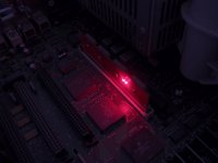
I actually ended up taking the same picture at different exposures and used some HDR magic to try to make the individual LEDs visible...it's not perfect but it looks closer to reality than any of the individual pictures!
8-o ;D
Nice work Doug!
If I can offer a suggestion from the peanut gallery: keep it simple with the programmer board, and leave it up to the individual what to put in the ROM. If someone can find a way to hack in a ROM-disk using portions of the Mac Classic ROM driver, awesome! But I don't think that will really change your hardware. For the programmer, have you done a rough estimate of home much the programming board might cost? If it's a significant fraction of the cost of an EPROM programmer, then it may make more economic sense for people to buy the EPROM programmer instead of a single-purpose SIMM programmer. Of course there are other non-financial reasons to build a programmer board, like the intellectual challenge and satisfaction of a home-built tool. None of my projects have ever made economic sense, but my wife keeps telling me they should.
If I can offer a suggestion from the peanut gallery: keep it simple with the programmer board, and leave it up to the individual what to put in the ROM. If someone can find a way to hack in a ROM-disk using portions of the Mac Classic ROM driver, awesome! But I don't think that will really change your hardware. For the programmer, have you done a rough estimate of home much the programming board might cost? If it's a significant fraction of the cost of an EPROM programmer, then it may make more economic sense for people to buy the EPROM programmer instead of a single-purpose SIMM programmer. Of course there are other non-financial reasons to build a programmer board, like the intellectual challenge and satisfaction of a home-built tool. None of my projects have ever made economic sense, but my wife keeps telling me they should.
Thanks! I totally agree with what you're saying -- get the board done and then worry about all the cool applications for it. That's exactly what I plan to do, for sure. I have done a rough guess-timate a few pages back:
Either way, I'm still making the board just for the intellectual satisfaction as you said I don't even care if I make money or break even, it's just a fun thing to work on in my spare time. There's not a huge market for this product anyway (I've only sold 3 SIMMs). But yeah, now that I've gotten the hang of designing circuit boards, I want to prove to myself that I can learn how to make one with a microcontroller on it. I'm going to use EAGLE for this one, and it has taken me a while to get comfortable with it, but I'm getting there.
It's starting to approach the $40-ish price of an EEPROM programmer, but there are advantages:
- the PLCC sockets are no longer absolutely necessary, and even if they are still there you aren't constantly removing them (lowers the price of the SIMM if not there, and makes it more reliable -- PLCC sockets are terrible and flimsy and the chip's contacts get worse and worse the more you remove/reinsert them, even with the nice extractor tool)
- All 4 chips are programmed simultaneously so it's 4X faster to flash (assuming I can match the performance of my EEPROM programmer)
- The cheap EEPROM programmers require a Windows PC with a built-in or PCI/PCI Express parallel port (USB adapters don't work), and this would work with anything that you can get serial into (either with a serial port or USB), whether Mac, Linux, Windows, or whatever else OS we can dream up
Either way, I'm still making the board just for the intellectual satisfaction as you said
I don't even care if I make money or break even, it's just a fun thing to work on in my spare time. There's not a huge market for this product anyway (I've only sold 3 SIMMs). But yeah, now that I've gotten the hang of designing circuit boards, I want to prove to myself that I can learn how to make one with a microcontroller on it. I'm going to use EAGLE for this one, and it has taken me a while to get comfortable with it, but I'm getting there.The lower portion of the single (battery backed up) SRAM IC (or a standard SRAM Card in a socket on the "ROM SIMM" Card) emulates the four ROM ICs on your Revs 1 & 2 ROM SIMMs.
This leaves plenty of PCB real estate on the Gen3 "ROM SIMM" for the loading/address transmitting microcontroller and a micro USB(?) port/interface for comms with programmer/expansion card.
This stand alone card with a more capable microcontroller/translation circuitry, etc. will just need a power takeoff from the FDD Cable or a splitter for the HDD power cable.
This "expansion" card would have a micro USB port for communicating with the "ROM SIMM's" microcontroller and another micro USB(?) port for the cable to a single, female USB(?) panel mount socket to be placed in any appropriate space so that you can plug a USB(?) keychain/thumb drive into the Mac.
Does this make any more sense to you? :?:
I'm guessing the least common denominator would be USB1, but maybe the microcontrollers can do USB2 by now? :?:
I'm just spitballin' here too! :
We used an entire PC with a custom parallel interface card/cable combo to program the SRAM on our "Font Emulator" from files stored on the PC's HDD.
Ah, OK! For read-only USB access. I see where you're going, and that would be possible. I think I would probably use something other than USB between the SIMM and the extra board in that case just because USB can be kind of complicated to set up, and doesn't really seem ideal for communication between two microcontrollers. Actually, it might even be possible just to put the USB directly onto the SIMM and call it good. Who knows...
More brainstorming about the programmer board that I'm planning on making:
Originally I was thinking AVR, but now I'm thinking maybe a 5V Cortex-M3 would work well, especially one with built-in USB. Then I could avoid the FTDI chip and get both USB and serial both for free...although the USB becomes a bit more complicated because I would have to provide a USB stack and appropriate code to use it as a USB CDC device (which is probably available online). In particular, this chip looks very interesting.
More brainstorming about the programmer board that I'm planning on making:
Originally I was thinking AVR, but now I'm thinking maybe a 5V Cortex-M3 would work well, especially one with built-in USB. Then I could avoid the FTDI chip and get both USB and serial both for free...although the USB becomes a bit more complicated because I would have to provide a USB stack and appropriate code to use it as a USB CDC device (which is probably available online). In particular, this chip looks very interesting.