

Thread
Another IIci ROM hack
Oh thanks! I didn't see the $49 license when I was looking at their pricing. I think I can purchase the $49 license and rotate the SIMM socket 30 degrees or so. That way it fits on the board. It looks kind of funny, but it will work! That makes me happy because I've taken all this time to learn how to use EAGLE, and I'd rather not have to learn another one 
I've added a link to your index to the top post, dougg3. I'll add the index itself when I'm on a computer. It was too big for my phone's copy buffer, lol
Done deal! :approve:
Thanks Bunsen & jt! Looks great!
I'm not properly set up workshop-wise just yet, nor do I have an EPROMmer. So I'm kinda waiting to see how the prog board works out

I have to ask: who's gonna be the first person here to add a Formula 1 engine starting up for their boot chime on 3 or 4 Macs, then start them up so it sounds like the start of a race?  *vrrooooom*
Edit: Woo! Page 18. )
)
*vrrooooom*Edit: Woo! Page 18.
)
Haha, that would be cool!
I am now a paid, licensed user of EAGLE (the basic $49 license) and I think I have a basic schematic for the programmer board pretty close to ready. I'm also awaiting an AVR USB development board. I may be able to do some basic testing with that before I have a board manufactured. So progress is slowly but surely being made!
My plan for now is to always be powered by USB, and I'm also leaving space to add a MAX232 RS232 transceiver. I'm probably going to skip the TTL and level shifter especially since USB will be standard. If someone really wants it, the pads where the MAX232 belong are available
I am now a paid, licensed user of EAGLE (the basic $49 license) and I think I have a basic schematic for the programmer board pretty close to ready. I'm also awaiting an AVR USB development board. I may be able to do some basic testing with that before I have a board manufactured. So progress is slowly but surely being made!
My plan for now is to always be powered by USB, and I'm also leaving space to add a MAX232 RS232 transceiver. I'm probably going to skip the TTL and level shifter especially since USB will be standard. If someone really wants it, the pads where the MAX232 belong are available
Cool beans! I'm saving my pocket change!
I was thinking more along the lines of "Wipeout" or the "1812 Overture.")
"TAPS" for a death chime would be awesome!
I was thinking more along the lines of "Wipeout" or the "1812 Overture."
) "TAPS" for a death chime would be awesome!
I like the http://www.apple.com/safari/welcome sound for the chime, just out of spite :lol:
I was thinking that or The Funeral March xx(
So who's gonna be the first to play a practical joke, and set the death chime as the normal boot chime on some unsuspecting Mac user?
LOL, I had mine that way when I was still learning how to use the ASC. Even though I knew it was there, it STILL freaked me out every time I booted it!
IIRC, there used to be an April Fools Day program/extension that'd do that without even mucking about in ROM.
It played the dead Mac tones and displayed the Sad Mac right after, or during, the bootup process.
If a co-worker was hammering on project with a ridiculous deadline . . .
. . . that was the best possible time to load it on their machine! }
It played the dead Mac tones and displayed the Sad Mac right after, or during, the bootup process.
If a co-worker was hammering on project with a ridiculous deadline . . .
. . . that was the best possible time to load it on their machine! }
Good news and bad news.
Good news: I got my SIMM and it's totally awesome. It's better than anything I ever expected.
Bad news: My Daystar Digital '040 upgrade doesn't like it. I get the Chime o' Death if I have both the custom ROM and my accelerator installed.
What I don't know is if the Daystar dies with any ROM installed, or if it's just the one I have. Maybe it's looking for a specific something or another? When I have the Daystar Digital installed, it does bring up its own custom Happy Mac. Maybe that's where the problem lies?
Looks like some investigating is in order. I'm may end up mailing dougg3 my upgrade card so he can barrow it and see if he can't figure out what's going on.
Edit: This just in: I didn't pull the ROM jumper on the motherboard. I'm gonna go try that real quick and see if makes any difference.
Good news: I got my SIMM and it's totally awesome. It's better than anything I ever expected.
Bad news: My Daystar Digital '040 upgrade doesn't like it.
I get the Chime o' Death if I have both the custom ROM and my accelerator installed.What I don't know is if the Daystar dies with any ROM installed, or if it's just the one I have. Maybe it's looking for a specific something or another? When I have the Daystar Digital installed, it does bring up its own custom Happy Mac. Maybe that's where the problem lies?
Looks like some investigating is in order. I'm may end up mailing dougg3 my upgrade card so he can barrow it and see if he can't figure out what's going on.
Edit: This just in: I didn't pull the ROM jumper on the motherboard. I'm gonna go try that real quick and see if makes any difference.
The ROM jumper most definitely has to be pulled in order for it to boot with the SIMM at all
When I have tried in the past to boot the IIci with my SIMM installed and the jumper installed, I'm pretty sure I didn't get a chime at all. The fact that you get a death chime at all with both the SIMM and jumper installed is weird...
When I have tried in the past to boot the IIci with my SIMM installed and the jumper installed, I'm pretty sure I didn't get a chime at all. The fact that you get a death chime at all with both the SIMM and jumper installed is weird...
Shoot. Pulling the jumper didn't change anything. Looks like an incompatibility with my accelerator card.
Weirdly enough, I hadn't pulled the Alternate ROM jumper when inserted the SIMM the first time, and it booted fine (that was without my accelerator.)
Edit: I also don't get a sad Mac or any error codes. It's a blank screen.
Weirdly enough, I hadn't pulled the Alternate ROM jumper when inserted the SIMM the first time, and it booted fine (that was without my accelerator.)
Edit: I also don't get a sad Mac or any error codes. It's a blank screen.
Hmm, but it does work when the accelerator card is removed? Also, something weird is going on if the jumper was installed and the SIMM booted OK. That shouldn't work. If it does work, something is wrong.
Sounds like the accelerator card is doing something weird. Maybe it patches the ROM somehow or something? When you're booted without the SIMM but with the accelerator installed and operating, let's look at the stored ROM checksum to make sure it matches the stock IIci ROM checksum. Hit the programmer's switch after you're booted. Type:
DM 40800000
And hit return. Let me know what the first 4 bytes are (first 8 hex digits). To get out of the debugger, type G and press return.
Sounds like the accelerator card is doing something weird. Maybe it patches the ROM somehow or something? When you're booted without the SIMM but with the accelerator installed and operating, let's look at the stored ROM checksum to make sure it matches the stock IIci ROM checksum. Hit the programmer's switch after you're booted. Type:
DM 40800000
And hit return. Let me know what the first 4 bytes are (first 8 hex digits). To get out of the debugger, type G and press return.
800000 368C ADFE
It does have its own Happy Mac, so I think you're right. I bet it patches the ROM.
It does have its own Happy Mac, so I think you're right. I bet it patches the ROM.
That is the stock IIci ROM checksum...hmm. I was thinking if they changed the ROM they would have had to change the checksum too, to make the checksum test work. Or maybe they disable the checksum test altogether. I was just wondering in case the death chimes were caused by the checksum not matching. It's possible that the card is expecting to patch a stock ROM and when a patched ROM is present, it puts its own patches in that don't work, or something.
That's just a quick guess...this might be tough to figure out. The next logical step would be to put a stock IIci image on the SIMM and see if the update card boots with *that* present.
We should also figure out why your IIci boots from a custom SIMM when the ROM select jumper is inserted. Because it shouldn't....I'll test mine again just to make sure, but it really shouldn't work
Edit: mine works from the SIMM when the ROM select jumper is in, too. Maybe we're overpowering the internal chips or something? I would say that both the SIMM's chips and the DIP ROMs are fighting when their outputs differ, and the SIMM's chips are winning. I guess it works, but it's better to leave the jumper off whenever the SIMM is in Anyway, that knocks down item #2 I guess.
That's just a quick guess...this might be tough to figure out. The next logical step would be to put a stock IIci image on the SIMM and see if the update card boots with *that* present.
We should also figure out why your IIci boots from a custom SIMM when the ROM select jumper is inserted. Because it shouldn't....I'll test mine again just to make sure, but it really shouldn't work
Edit: mine works from the SIMM when the ROM select jumper is in, too. Maybe we're overpowering the internal chips or something? I would say that both the SIMM's chips and the DIP ROMs are fighting when their outputs differ, and the SIMM's chips are winning. I guess it works, but it's better to leave the jumper off whenever the SIMM is in
Anyway, that knocks down item #2 I guess.
Just another idea, have you tried dumping the ROM using a ROM dumper app when booted with the upgrade card and comparing it to a stock IIci ROM dump (which you could get by booting from the IIci with neither the SIMM nor the upgrade card installed)?
If the Happy Mac is changing, I'm almost certain that there's some kind of ROM patching weirdness going on, as you said too. I'd like to see if reading the ROM shows any patches, or if it just reads the stock ROM. Either way, this is some weird stuff!
If the Happy Mac is changing, I'm almost certain that there's some kind of ROM patching weirdness going on, as you said too. I'd like to see if reading the ROM shows any patches, or if it just reads the stock ROM. Either way, this is some weird stuff!
I remember being confused by the jumper and possibly never following through to completely figure it out. It may not work exactly the way that we might expect. I clearly remember being baffled by my then damaged Mac IIci starting from my IIfx SIMM when the onboard ROM was not working (corroded trace) and the jumper was set either way. It seemed to me that the SIMM almost could override the onboard ROM regardless of the jumper, and at that point I wondered if these extra VCC lines in the SIMM may actually be sending info back to the Mac somehow, telling it that there's a SIMM there. It was ALL speculation though. Further testing is necessary.
Interesting! Naturally since you mentioned that, I grabbed my multimeter and played around to see what exactly the ROM SELECT jumper does. Here are some tidbits (I have taken the ROM select jumper out):
The resistance between the DIP ROMs' chip select pin and the ROM SIMM socket's A19 contact is 1.3 ohms. They're pretty much shorted together. The DIP ROMs' chip select pins are NOT connected to the SIMM socket's chip select pin.
The resistance between the DIP ROMs' output enable pin and the bottom pin of the W1 (ROM SELECT) jumper is 1 ohm. They're pretty much shorted together. They show a 4.7k resistance to both +5V and GND (not surprising since +5V and GND only have a resistance of about 16 ohms between each other). If I power on the IIci with the jumper removed, the pin shows +5V, so I'm going to have to say that it's a 4.7k pull-up resistor to +5V.
The resistance between the SIMM socket's output enable pin and the top pin of the W1 jumper is 0 ohms. It doesn't appear to be connected to +5V or GND, so this is probably the actual output enable line of the CPU/bus/whatever.
The chip select pin of the SIMM socket is shorted to ground.
All the VCC pins on the SIMM socket are shorted together.
In conclusion:
The DIP ROMs' active-low output enable pins are connected to a 4.7k pull-up resistor to +5V, so the DIP ROMs won't write anything to the data bus if the jumper is removed. If the jumper is put in place, it connects them to the actual output enable line, overriding the pull-up resistor, so they will write to the data bus when requested. BUT....the chip select line also matters as I describe below.
The connection between the DIP ROMs' chip select pin and A19 is very, very interesting, especially considering that the DIP ROMs themselves only go up to A18 (keeping in mind that A0 and A1 are unused). As far as I can tell, it turns the DIP ROM chip select pin into another address line. If A19 is zero, the DIP ROMs are activated. If it's 1, the DIP ROMs are deactivated.
The ROM SIMM's chip select is always activated since it's connected to ground.
I don't think the VCC pins do anything special...
So if the jumper is on, and a ROM SIMM is in, I'm thinking that the DIP ROMs will be activated for the first 512k of ROM space, and then deactivated for the next 512k of ROM space, then activated for the next 512k of ROM space, and so on. Does this sound right to the hardware gurus? I tried to verify with MicroBug, but whenever I try to dump 0x40900000, which would be the first repetition location after the base ROM address of 0x40800000, it crashes out of MicroBug back to the desktop. Even with my SIMM which *definitely* has data at that location since it has 2 MB of space. Ugh...I'm pretty sure the ROM should be repeating at that location.
OK, that was with System 7.0.1. My other IIci runs System 7.6 and is showing exactly what I thought -- the first 512K is the ROM, the next 512K is filled with 0xFFs, the next 512K (where A19=0 again) is the ROM, and that repeats throughout the entire ROM space.
So it seems like the SIMM and the DIPs should be conflicting with each other half of the time if the jumper is left in place while the SIMM is also in there. I'm still thinking the chips on the SIMM are just stronger outputs than the DIP chips in that case...
Anyway, this theoretically means you could make a ROM SIMM that is an ADD-ON to the existing ROM space. You leave the stock ROM in place and it still boots from it, but then you use the other unused alternating 512K spaces of ROM where A19=1 to put additional stuff, and leave the ROM select jumper in place. Doesn't seem too useful to me when we are able to modify the ENTIRE ROM to do stuff like custom startup chimes, but it's still interesting.
Wow. That was a lot to write. What do you guys think?
The resistance between the DIP ROMs' chip select pin and the ROM SIMM socket's A19 contact is 1.3 ohms. They're pretty much shorted together. The DIP ROMs' chip select pins are NOT connected to the SIMM socket's chip select pin.
The resistance between the DIP ROMs' output enable pin and the bottom pin of the W1 (ROM SELECT) jumper is 1 ohm. They're pretty much shorted together. They show a 4.7k resistance to both +5V and GND (not surprising since +5V and GND only have a resistance of about 16 ohms between each other). If I power on the IIci with the jumper removed, the pin shows +5V, so I'm going to have to say that it's a 4.7k pull-up resistor to +5V.
The resistance between the SIMM socket's output enable pin and the top pin of the W1 jumper is 0 ohms. It doesn't appear to be connected to +5V or GND, so this is probably the actual output enable line of the CPU/bus/whatever.
The chip select pin of the SIMM socket is shorted to ground.
All the VCC pins on the SIMM socket are shorted together.
In conclusion:
The DIP ROMs' active-low output enable pins are connected to a 4.7k pull-up resistor to +5V, so the DIP ROMs won't write anything to the data bus if the jumper is removed. If the jumper is put in place, it connects them to the actual output enable line, overriding the pull-up resistor, so they will write to the data bus when requested. BUT....the chip select line also matters as I describe below.
The connection between the DIP ROMs' chip select pin and A19 is very, very interesting, especially considering that the DIP ROMs themselves only go up to A18 (keeping in mind that A0 and A1 are unused). As far as I can tell, it turns the DIP ROM chip select pin into another address line. If A19 is zero, the DIP ROMs are activated. If it's 1, the DIP ROMs are deactivated.
The ROM SIMM's chip select is always activated since it's connected to ground.
I don't think the VCC pins do anything special...
So if the jumper is on, and a ROM SIMM is in, I'm thinking that the DIP ROMs will be activated for the first 512k of ROM space, and then deactivated for the next 512k of ROM space, then activated for the next 512k of ROM space, and so on. Does this sound right to the hardware gurus? I tried to verify with MicroBug, but whenever I try to dump 0x40900000, which would be the first repetition location after the base ROM address of 0x40800000, it crashes out of MicroBug back to the desktop. Even with my SIMM which *definitely* has data at that location since it has 2 MB of space. Ugh...I'm pretty sure the ROM should be repeating at that location.
OK, that was with System 7.0.1. My other IIci runs System 7.6 and is showing exactly what I thought -- the first 512K is the ROM, the next 512K is filled with 0xFFs, the next 512K (where A19=0 again) is the ROM, and that repeats throughout the entire ROM space.
So it seems like the SIMM and the DIPs should be conflicting with each other half of the time if the jumper is left in place while the SIMM is also in there. I'm still thinking the chips on the SIMM are just stronger outputs than the DIP chips in that case...
Anyway, this theoretically means you could make a ROM SIMM that is an ADD-ON to the existing ROM space. You leave the stock ROM in place and it still boots from it, but then you use the other unused alternating 512K spaces of ROM where A19=1 to put additional stuff, and leave the ROM select jumper in place. Doesn't seem too useful to me when we are able to modify the ENTIRE ROM to do stuff like custom startup chimes, but it's still interesting.
Wow. That was a lot to write. What do you guys think?
Will this help somehow? From IIsi dev.note.
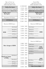
Thanks ojfd -- I have that (as well as the IIci's version which is in Guide to the Macintosh Family Hardware), but it's basically showing that the ROMs repeat throughout that entire space of 0x40000000 to 0x42000000. (In fact I see a typo on the chart -- it should be 40800000, not 48000000 below 42000000).
None of the diagrams I have seen have ever mentioned what I just discovered tonight about the soldered ROMs only repeating in every other 512KB block due to the soldered ROMs' chip select line being tied to A19. It would be interesting to see if the IIsi has the same behavior. I would guess it does.
Anyway, no worries -- everything behaves as it should with my SIMM when the ROM select jumper is removed. (Well, except when olePigeon's accelerator card is installed -- the jury's still out on why that is). This is just me trying to understand the behavior if you accidentally leave the jumper in with the SIMM also in
BTW, in my other IIci that has socketed DIP ROMs with my custom DIP chips, if I put in my ROM SIMM and leave the jumper on, I get the chimes of death. I'm guessing this is because my custom DIP ROMs and the SIMM's chips get in a battle that neither can fully win, unlike the battle between the stock DIP ROMs and my SIMM's chips (where my SIMM's chips win against the stock DIP ROMs). So the checksum fails because I get random bits and pieces when the contents of the DIPs differ from the contents of my SIMM.
None of the diagrams I have seen have ever mentioned what I just discovered tonight about the soldered ROMs only repeating in every other 512KB block due to the soldered ROMs' chip select line being tied to A19. It would be interesting to see if the IIsi has the same behavior. I would guess it does.
Anyway, no worries -- everything behaves as it should with my SIMM when the ROM select jumper is removed. (Well, except when olePigeon's accelerator card is installed -- the jury's still out on why that is). This is just me trying to understand the behavior if you accidentally leave the jumper in with the SIMM also in
BTW, in my other IIci that has socketed DIP ROMs with my custom DIP chips, if I put in my ROM SIMM and leave the jumper on, I get the chimes of death. I'm guessing this is because my custom DIP ROMs and the SIMM's chips get in a battle that neither can fully win, unlike the battle between the stock DIP ROMs and my SIMM's chips (where my SIMM's chips win against the stock DIP ROMs). So the checksum fails because I get random bits and pieces when the contents of the DIPs differ from the contents of my SIMM.
:O Can I determine this this with a continuity tester? :?:
Yes -- in fact you can test it without a continuity tester if you want.
Hit the programmer's switch (wait, does the IIsi even have one? do you have to hit command-power key?) and type:
DM 40800000
This will show the beginning of ROM
Now type:
DM 40900000
This will show the first repetition of ROM, and it should be identical (if it crashes, like mine does in 7.0.1, that's OK)
Now type:
DM 40880000
Does it show another repetition of the ROM, or a bunch of FFs? If it shows a bunch of FFs, the IIsi is probably wired the same way as the IIci.
If you really want to test the continuity to see it, find the IIsi soldered ROMs and test each pin's continuity against SIMM socket pin 42. I don't know the pinout of the IIsi's soldered ROMs, but if anything shows continuity to the A19 pin, you have probably found it.
Hit the programmer's switch (wait, does the IIsi even have one? do you have to hit command-power key?) and type:
DM 40800000
This will show the beginning of ROM
Now type:
DM 40900000
This will show the first repetition of ROM, and it should be identical (if it crashes, like mine does in 7.0.1, that's OK)
Now type:
DM 40880000
Does it show another repetition of the ROM, or a bunch of FFs? If it shows a bunch of FFs, the IIsi is probably wired the same way as the IIci.
If you really want to test the continuity to see it, find the IIsi soldered ROMs and test each pin's continuity against SIMM socket pin 42. I don't know the pinout of the IIsi's soldered ROMs, but if anything shows continuity to the A19 pin, you have probably found it.
Here's what I have for a schematic right now. Hopefully this isn't too crazy...
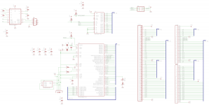
I ended up using every pin on the microcontroller.
The PRTR5V0U4D is for ESD protection when you're plugging/unplugging the USB cable.
CON1 is a 64-pin SIMM socket.
CON2 and CON3 are the Samtec headers I have as a backup plan if the SIMM sockets don't work out.
I ended up using every pin on the microcontroller.
The PRTR5V0U4D is for ESD protection when you're plugging/unplugging the USB cable.
CON1 is a 64-pin SIMM socket.
CON2 and CON3 are the Samtec headers I have as a backup plan if the SIMM sockets don't work out.
It doesn't really make much sense.
Let me rephrase...
The conclusions you've drawn from the evidence you've reported make sense.
Causing the logic board ROM to be inactive over 50% of the addresses doesn't make any sense.
If you want to create repeating images in the address space, you just arrange (logically/electrically) for Output Enable and Chip Enable to be Low whenever the chosen address space is addressed, and let the lower addresses roll over on the address pins of the device.
I can't think of any reason the designers would cause the ROM to roll over half as often as it should.
Other thought: I don't think olePigeon ever reported whether his ROM works with the jumper removed and the Daystar upgrade removed.
If his ROM is functional, then the explanation for his IIci booting up with the jumper and ROM SIMM installed may be that the logic board ROMs and the SIMM ROMs are synchronized enough to not cause any problems when the Daystar upgrade is not present. However, the presence of the Daystar upgrade changes the timings enough to screw things up when they're both active. That's assuming that the SIMM and the logic board ROMs have the same code installed.
A little far fetched, but possible, I think.
I haven't been around in a while. Great work, by the way. I admire your creation.
olePigeon, does that parts shop near you have 160 pin DIMM sockets with keys between 30 -31 and 55 -56. Since it's 1 - 80 on one side and 81 - 160 on the other side, the keys are also between 110 - 111 and 135 - 136.
Hey trag,
Thanks!
I wrote that thing pretty quickly and didn't make it clear when I wrote it -- that's the way the factory DIP ROMs behave with no SIMM installed at all. I'm guessing you already picked up on that, but I just reread my post and it was really confusing because I kept mentioning the SIMM even though it didn't really apply. Just thought I'd make sure that we're on the same page there. I don't understand the whole "A19 = chip select" thing either. I'm wondering if maybe it was originally going to serve as a "chip select 0", with "chip select 1" being the inverted output of the same address line? So that way the extra 512KB of space between every ROM repetition would be where the second ROM bank would go. Maybe they were originally planning on putting 1 MB of soldered ROM into it, using that technique for the chip selects? But even then, aren't there better ways to do that, like you mentioned? Anyway, I agree, it doesn't make a lot of sense from a design standpoint.
Thanks!
I wrote that thing pretty quickly and didn't make it clear when I wrote it -- that's the way the factory DIP ROMs behave with no SIMM installed at all. I'm guessing you already picked up on that, but I just reread my post and it was really confusing because I kept mentioning the SIMM even though it didn't really apply. Just thought I'd make sure that we're on the same page there. I don't understand the whole "A19 = chip select" thing either. I'm wondering if maybe it was originally going to serve as a "chip select 0", with "chip select 1" being the inverted output of the same address line? So that way the extra 512KB of space between every ROM repetition would be where the second ROM bank would go. Maybe they were originally planning on putting 1 MB of soldered ROM into it, using that technique for the chip selects? But even then, aren't there better ways to do that, like you mentioned? Anyway, I agree, it doesn't make a lot of sense from a design standpoint.
On some Macs, the ROM/ROM SIMM was meant to be, and was implemented in the memory map as, an expansion of ROM as a storage medium. But on others, it was only meant to act as the Mac's mundane Boot Code/ToolBox Routine Repository. In these Macs, there was no provision for ROM based storage expansion in the Memory Map. I need to find the page, IIRC it was in GttMFH2e, with the table listing which Macs had which of those two very different types of Memory Mapping/ROM configurations.
Might this explain some of the strange ROM/ROM SIMM juju that appears to be cropping up? :?:
Does the Area 19 Mystery have anything to do with the Jumper Pin on/off config?
Are those pins tied together on the MoBo ROMs?
Dunno, I'm just tossin' 'em out there as they pop into the 'ole noggin' before they leak outta my ears. :-/
N.B. trag, I edited your text to "I haven't been around," that being what appeared to be your meaning from the context. If not, I'll correct it if you let me know.
Might this explain some of the strange ROM/ROM SIMM juju that appears to be cropping up? :?:
Does the Area 19 Mystery have anything to do with the Jumper Pin on/off config?
Are those pins tied together on the MoBo ROMs?
Dunno, I'm just tossin' 'em out there as they pop into the 'ole noggin' before they leak outta my ears. :-/
N.B. trag, I edited your text to "I haven't been around," that being what appeared to be your meaning from the context. If not, I'll correct it if you let me know.
It doesn't have anything to do with the jumper -- the chip select pin of the DIPs is connected to A19, regardless of the jumper setting I'm still very interested if you get a chance to test this on your IIsi. I suspect it will have the same behavior, but it's definitely interesting!
I'm still very interested if you get a chance to test this on your IIsi. I suspect it will have the same behavior, but it's definitely interesting!