

Thread
Another IIci ROM hack
ISTR, that for the Mac Portable, the VERY large ROM Memory Space was meant to store programs and such in non-volatile, solid state memory.
Figuring on that, I don't see why Block-Banging good sized chunks of data from a Micro-Controller to your ROM SIMM and then to the MAC should be a big deal. You could even use cable drivers and a short parallel cable to connect the two PCBs inside the box with the USB port mounted on an empty section of backplane cover plate.
An all discrete gating logic config run over a parallel connection to your "ROMs" keeps the ROM SIMM simple/proc free & small!
Figuring on that, I don't see why Block-Banging good sized chunks of data from a Micro-Controller to your ROM SIMM and then to the MAC should be a big deal. You could even use cable drivers and a short parallel cable to connect the two PCBs inside the box with the USB port mounted on an empty section of backplane cover plate.
An all discrete gating logic config run over a parallel connection to your "ROMs" keeps the ROM SIMM simple/proc free & small!
You can get around this by using a transistor.
Connect + of the LED to +5V, - of the LED through your resistor that you mentioned before to the collector of an NPN transistor. Connect the emitter of the transistor to ground. Then connect the base of the transistor to the output enable through a 10k resistor for example. You are using the transistor as a switch to turn the LED on and off, and you are controlling the switch with very small power from the the output enable.
This takes only two extra parts: a transistor and a resistor.
Then you have to pay attention to fanout. Just have to gauge the base current of the transistor, from the circuits driving it. because if your not careful, the base current would be enough to throw it into overload, burning up the chip that runs the OE line. Of course the posibility of this is extremely remote, but it can happen (experience, blew 74HC595s this way).
Best to use an SMD logic-level FET, its a voltage controlled device, not a current controlled device, so it would lighten the load on the digital circuits tremendously, at the cost of a pull-down resistor. (or pull-up depending on the active state of the OE line). If OE is active low, you'll want a P-Channel FET so the LED only comes on when OE is enabled.
just a tip....
Best to use an SMD logic-level FET, its a voltage controlled device, not a current controlled device, so it would lighten the load on the digital circuits tremendously, at the cost of a pull-down resistor. (or pull-up depending on the active state of the OE line). If OE is active low, you'll want a P-Channel FET so the LED only comes on when OE is enabled.
just a tip....
Ooh, that's very true! That way I could make a bigger board that wasn't constrained by the SIMM size. I like it! We could put all kinds of cool stuff into it that way.
Ah, I see! That makes perfect sense. Thanks for the info. Just curious, what is the purpose of the 10k resistor, and how did you figure out that it should be around that value? Is it restricting the current that the transistor can draw, similar to how you use a resistor to limit the current an LED can draw?
Thanks for this info too! OE is active low, so P-channel it is. Going this route, do I still need the 10k resistor, or when you say it's voltage controlled, does that mean that the 10k resistor isn't necessary any more because the current doesn't matter? Also, where would the pull-up/pull-down resistor need to go? On the base?
MOSFET doesnt have Base Collector Emitter. it has Gate Source Drain.
You would tie the gate into the OE circuit. You would then use a small 1k pullup from Gate to Source. Source tied to 5V. Drain tied to LED anode, LED cathode to ground.
all you need. IF you want to feel safe, you can put a 100ohm resistor between gate and main circuit. But if you use a standard mosfet that has a +/-10v or +/-20v Gate voltage, a resistor is NOT necessary, except a pullup, however the resistor offers some protection in case the MOSFET decides to ever short, it wont hold your OE line, becuase if it shorts, not only would the LED remain lit, but your OE would be forced high through the Gate to Source short, if one occurs. A gate resistor would prevent a hard short, so there is a chance the OE circuit could still pull low.
In a condition without the resistor, and the MOSFET shorts, OE could certainly try to pull low in that situation, but the pulldown transistor would overload and short out. leaving the OE stuck forever because the resistor isnt there to provide ballast from a hard short. So a 100ohm or so gate series resistor would be a good idea in case of a MOSFET short, so it dont blow your OE circuit.
in a 5v circuit tho, its VERY UNLIKELY the mosfet driving the LED could ever short, but given these chinese junk parts of today, you never know.... just design a circuit with that in mind... Dont need a chinese peice of shit taking out a pulldown transistor in a VLSI chip if it ever decides to short If you opt-out on the resistor to favor more transistor saturation, if it shorts, youll know becuase the mac wont startup and the VLSI will get hot fast.
You would tie the gate into the OE circuit. You would then use a small 1k pullup from Gate to Source. Source tied to 5V. Drain tied to LED anode, LED cathode to ground.
all you need. IF you want to feel safe, you can put a 100ohm resistor between gate and main circuit. But if you use a standard mosfet that has a +/-10v or +/-20v Gate voltage, a resistor is NOT necessary, except a pullup, however the resistor offers some protection in case the MOSFET decides to ever short, it wont hold your OE line, becuase if it shorts, not only would the LED remain lit, but your OE would be forced high through the Gate to Source short, if one occurs. A gate resistor would prevent a hard short, so there is a chance the OE circuit could still pull low.
In a condition without the resistor, and the MOSFET shorts, OE could certainly try to pull low in that situation, but the pulldown transistor would overload and short out. leaving the OE stuck forever because the resistor isnt there to provide ballast from a hard short. So a 100ohm or so gate series resistor would be a good idea in case of a MOSFET short, so it dont blow your OE circuit.
in a 5v circuit tho, its VERY UNLIKELY the mosfet driving the LED could ever short, but given these chinese junk parts of today, you never know.... just design a circuit with that in mind... Dont need a chinese peice of shit taking out a pulldown transistor in a VLSI chip if it ever decides to short
If you opt-out on the resistor to favor more transistor saturation, if it shorts, youll know becuase the mac wont startup and the VLSI will get hot fast.
WOOHOO!!!!!!!!!!!! 12 pages and counting! 275 replies and 5,018 views for a new recruit's introductory post! :approve:
Modern EEPROMs (?) and such make the hardware just a tad smaller, the input end of our parallel cable to the ROM emulator was an all discrete logic ISA Card, the Proc & Storage was a friggin' PC and its HDD!
Now you could do it on a slightly oversize ROM Card, but to build your own "PC" for inside the Mac with today's technology is just wild and waaayyyyyy over my head!
Just the LED discussion gives me a headache! :I
edit: your base card remains as useful as, and not a lot more expensive than, the cards you have running right now.
The feeder card would be an option to be added at any time and the input cable opens up the "system' to development by the rest of the PoAMM contingent of the 68kMLA! [ ] ]'>
] ]'>
That's the exact config we used back in '89-'90 to feed info to the four 32k SRAM Chips that "emulated" EPROMs on standard $300 font cards.
Modern EEPROMs (?) and such make the hardware just a tad smaller, the input end of our parallel cable to the ROM emulator was an all discrete logic ISA Card, the Proc & Storage was a friggin' PC and its HDD!
Now you could do it on a slightly oversize ROM Card, but to build your own "PC" for inside the Mac with today's technology is just wild and waaayyyyyy over my head!
Just the LED discussion gives me a headache! :I
edit: your base card remains as useful as, and not a lot more expensive than, the cards you have running right now.
The feeder card would be an option to be added at any time and the input cable opens up the "system' to development by the rest of the PoAMM contingent of the 68kMLA! [
] ]'>
I agree that the mosfet is a better choice, it did cross my mind, but I thought people may be more widely familiar with ordinary bjt transistors from science projects and such. Also you have to worry about weird stuff with mosfets, like the gate storing a charge unless you add some megohm resistor to it or something. The example was written with simplicity in mind.
The 10k was a random number, it depends on voltages and the transistor, etc. 100k could have been another example.
If you do want to make an LED show the OE status, let us know and one of us will scribble something out that uses a tiny little mosfet for you. It's much easier to explain with a picture.
The 10k was a random number, it depends on voltages and the transistor, etc. 100k could have been another example.
If you do want to make an LED show the OE status, let us know and one of us will scribble something out that uses a tiny little mosfet for you. It's much easier to explain with a picture.
thats why i said to use a pullup on the mosfet. for that reason.
Ah, thanks for the info you guys. Transistors are confusing (to me!). I think for simplicity I'm going to just keep them lit at all times. I don't know how often the ROM is accessed anyway, so for all I know, the light might barely blip on at all except at power up, which would make the whole thing a waste. Plus, the case is closed, so it's probably not an essential feature.
I'll try to finish the design, post some pics on here, and send out for more PCBs soon. I'll probably do an order of 50 boards this time...I'll also post my FreePCB project file if anyone wants to make or mod their own.
Wish I could make it USB programmable, but I just don't think I can make it fit unless I do something like jt mentioned with cables connecting to a bigger board. An external board with a SIMM socket and USB port may be the way to go. Is there any alternative to SIMM sockets I could use to make contact with the SIMM contacts for programming?
I'll try to finish the design, post some pics on here, and send out for more PCBs soon. I'll probably do an order of 50 boards this time...I'll also post my FreePCB project file if anyone wants to make or mod their own.
Wish I could make it USB programmable, but I just don't think I can make it fit unless I do something like jt mentioned with cables connecting to a bigger board. An external board with a SIMM socket and USB port may be the way to go. Is there any alternative to SIMM sockets I could use to make contact with the SIMM contacts for programming?
How about putting another, more common type of connector on the top of the SIMM for programming? Is there space for two rows of 0.1" header? Or just pick any connector type that's fairly common, and small enough to fit. Connect the traces from the programming header to the matching traces from the SIMM edge connector, and you're done.
64 pin sockets seem to be hard to find. Someone here did mention their local shop had a bunch of 64 pin sockets.
How about using a 72 pin SIMM connector if the pin pitch is the same and holding it in place while it programs (not ideal but reminds me of an old MacWorld article that suggested using rubber bands to hold SIMMs with broken retaining clips)? Perhaps a 72 pin SIMM could be cut down to 64 pins by snipping bits in-between and then when soldered may not be noticeable. That could work if the retaining clips and notch locators are the same at the ends. Just some ideas...
How many pins total are needed to program all the chips on the ROMM?
How about using a 72 pin SIMM connector if the pin pitch is the same and holding it in place while it programs (not ideal but reminds me of an old MacWorld article that suggested using rubber bands to hold SIMMs with broken retaining clips)? Perhaps a 72 pin SIMM could be cut down to 64 pins by snipping bits in-between and then when soldered may not be noticeable. That could work if the retaining clips and notch locators are the same at the ends. Just some ideas...
How many pins total are needed to program all the chips on the ROMM?
This could definitely work, and it would be cheap too (I'm pretty sure SIMM sockets are fairly expensive). The main challenge is that all the data lines are on the bottom of the SIMM and I may have some trouble bringing them to the top. If at all possible I'd prefer to just use the existing connector...or maybe try to fit the header near the bottom of the board. In fact...I already have vias on all the SIMM contacts. Maybe I could make them big enough to solder in a header, while still leaving room for the SIMM to fit in its socket. I guess I have to be careful I don't get solder all over the contacts though.
Right--olePigeon found some. I'm just worried about the long term availability of them, that's why I'm thinking about a more common connector of some kind.
I'll play around with seeing how my SIMM fits in a 72-pin socket. I didn't think about that! For temporary programming purposes (which is exactly what we would be using it for), I bet it would work fine.
Each chip has 32 pins, 8 of which are unique to that chip, the other 24 are shared. It should be a total of 24+8+8+8+8=56 pins needed, I think.
The thickness of your SIMM is almost perfect for using the smaller header pins (.05" Centers?) along the top edge. I'll bet there are ribbon cables that come in a usable width to connect to whatever you want! [] ]'>
Use a pair of cables with the extra headers on one side of your SIMM tied to ground for alternate ground crosstalk prevention. }
] ]'>Use a pair of cables with the extra headers on one side of your SIMM tied to ground for alternate ground crosstalk prevention. }
I think I know what you're talking about, and 0.05" pitch is exactly what I'd need (it matches the SIMM contacts perfectly). I think if I could make them work on the BOTTOM of the SIMM, it would be easier so I wouldn't have to route all the data lines to the top. Even if I could just solder the ribbon cable to the SIMM and leave it floating when not in use or something...
What do you mean about using a pair of cables? Are you saying that I should add another ribbon cable with all ground wires to help with interference?
What do you mean about using a pair of cables? Are you saying that I should add another ribbon cable with all ground wires to help with interference?
Haven't touched the SIMM PCB layout yet (sorry! I'm still trying to figure out a way to squeeze user programmability into version 2 so everyone won't need an EEPROM burner). It'll probably involve another external programmer board.
I can now happily say that I can make boards without totally destroying the bottoms of the PLCC sockets. As you can see in the picture, I still do melt the plastic a little bit, but now that I have a small bent tip for my iron and a good needle tip and plunger for my solder paste syringe, it's looking like I can solder these sockets:
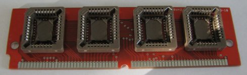
I can now happily say that I can make boards without totally destroying the bottoms of the PLCC sockets. As you can see in the picture, I still do melt the plastic a little bit, but now that I have a small bent tip for my iron and a good needle tip and plunger for my solder paste syringe, it's looking like I can solder these sockets:
or you can grab a tube of Zephaste solder paste, and heat the board up from the bottom. It will melt the paste into solder, and bond the sockets to the board without melting anything, you just need a tc (thermocouple) to monitor the temps, dont want to exceed 220c
That's the brand of solder paste I'm using. I really like it!
I wouldn't worry so much about the programmable version as yet.
Nailing down the current design's features-n-possible flaws ought to be the main focus for the nonce, IMHO.
Baby steps! :approve:
You've come along so successfully with the ROM SIMM design and with such amazing progress on your the startup sound hack . . .
. . . that maybe it's time to THINK! (blatant early Sixties IBM reference) [] ]'>
Nailing down the current design's features-n-possible flaws ought to be the main focus for the nonce, IMHO.
Baby steps! :approve:
You've come along so successfully with the ROM SIMM design and with such amazing progress on your the startup sound hack . . .
. . . that maybe it's time to THINK! (blatant early Sixties IBM reference) [
] ]'>
True true, but if it's as simple as making sure the vias that connect the top contacts to the bottom contacts are big enough and aligned, and then soldering a 0.05" pitch header in them, it would be nice to have the Rev. 2 SIMM board ready as soon as I have a programmer board designed I just found a promising header/socket pair and tried to get some free samples from Samtec. We'll see if they will let some random hobbyist order free samples from them or not!
I just found a promising header/socket pair and tried to get some free samples from Samtec. We'll see if they will let some random hobbyist order free samples from them or not!
you could also produce a double-edge SIMM. That way, one side inserts into the mac, and the other side fits a more common slot to program it, or potentially another mac.
I thought about that (I think BMOW suggested it also), but the problem is that I think it would be hard to get all of the traces (especially D0 through D31) to the top of the board. The PLCC chip layout puts the data pins all at the bottom of the board so that it's trivial to connect them all to their contacts. I think I'd have some trouble bringing them up to the top, especially since I'm using the bottom as my ground plane and I don't want to tear it up too much.
I could always stick everything in and see what the autorouter comes up with I guess...
I want to see how well the 0.05" pitch headers work. They might be too tiny and easily bendable/breakable. We'll have to see...
I could always stick everything in and see what the autorouter comes up with I guess...
I want to see how well the 0.05" pitch headers work. They might be too tiny and easily bendable/breakable. We'll have to see...
dougg3 sent me his ROM SIMM and helped me burn the ROM image to install in my SE/30. At first we were stumped because the custom chime did not sound. dougg3 discovered that earlier series II Macs use a different sequence. Once that part was figured, out the new startup chime works!
Here is my demo video on the result:
https://player.vimeo.com/video/30290934
Here is my demo video on the result:
https://player.vimeo.com/video/30290934
It's very cool to see a compact Mac with that startup sound! I'm still thinking about what it might take to fix the weird display pattern that appears.
Just for reference for anybody interested, it turns out that the SE/30 and other older II series Macs execute a different code path than the IIci when booting from a IIci ROM. My original patch only fixed the instruction that jumps to the startup chime for the IIci. There is another location in the ROM that also jumps to the sound playing code, and that code is used by the SE/30 and II at least. Although I don't have an SE/30 here, I was able to verify it using MESS. So now there are two locations to patch in the ROM. I'll post updated instructions on my blog later.
Just for reference for anybody interested, it turns out that the SE/30 and other older II series Macs execute a different code path than the IIci when booting from a IIci ROM. My original patch only fixed the instruction that jumps to the startup chime for the IIci. There is another location in the ROM that also jumps to the sound playing code, and that code is used by the SE/30 and II at least. Although I don't have an SE/30 here, I was able to verify it using MESS. So now there are two locations to patch in the ROM. I'll post updated instructions on my blog later.
Awesome video! With the gloves, outer space music, and talking moose voice, I was smiling the whole way through.
was the voice and the extreme bass necessary? i liked the video but all that was annoying.
I liked the sound effects! Especially the moaning sound as you replaced the ROM SIMM, it sounds like a zombie getting a brain transplant or something.
Haha, thanks for the feedback. I think you nailed it dougg3.
You folks are ALMOST tempting me to FINALLY install Flash . . . :
. . . but I SHALL CONTINUE TO RESIST ASSIMILATION BY THE 'NETBOOBTUBE! }
. . . but I SHALL CONTINUE TO RESIST ASSIMILATION BY THE 'NETBOOBTUBE! }
If you're using a modern browser, you can watch YouTube or Vimeo with HTML5. On tt's link, there's a tiny little "Switch to HTML5 player" link that won't require Flash. With YouTube, you can choose to view everything in HTML5 here:
http://www.youtube.com/html5
Uh oh, have I just sucked you in? ;-)
http://www.youtube.com/html5
Uh oh, have I just sucked you in? ;-)
