

Thread
Another IIci ROM hack
:O BUMP!!!!!!!!!!!!! }
I can't believe this thread dropped all the way down to page 2 of "Active" Topics! :-/
Meanwhile, back at the banana ranch . . . yo!!! dougg3!!!!!!
Have you considered a side by side comparison of ROM Dumps of the SE/30 <-> IIci <-> IIfx <-> IIsi in order to simplify your search methodology by eliminating repetitive/identical instruction sets and repetitive data sets?
With a comparative parser (?), you could identify blocks of instructions that are identical, even when stored at different address spaces on the four ROM samples.
Using a more complicated parser, you could identify blocks of instructions with a variable scale of change differential in similar blocks of instructions.
Kinda like running a PhotoShop Filter on sets/subsets of ROM instructions? :?:
If this is a standard feature of de-compiling (?) software a/o S.O.P. for such processes, forgive my ignorance, but I just HAD to ask! :
I can't believe this thread dropped all the way down to page 2 of "Active" Topics! :-/
Meanwhile, back at the banana ranch . . . yo!!! dougg3!!!!!!
Have you considered a side by side comparison of ROM Dumps of the SE/30 <-> IIci <-> IIfx <-> IIsi in order to simplify your search methodology by eliminating repetitive/identical instruction sets and repetitive data sets?
With a comparative parser (?), you could identify blocks of instructions that are identical, even when stored at different address spaces on the four ROM samples.
Using a more complicated parser, you could identify blocks of instructions with a variable scale of change differential in similar blocks of instructions.
Kinda like running a PhotoShop Filter on sets/subsets of ROM instructions? :?:
If this is a standard feature of de-compiling (?) software a/o S.O.P. for such processes, forgive my ignorance, but I just HAD to ask! :
Oh hi! I'm still here ;-) I just haven't had any reason to update while waiting for the PCBs to arrive. xx(
The most basic example would be a binary diff tool, but that would be very, very simple and probably wouldn't give much useful information -- for instance it doesn't know how to ignore jump targets. It would take quite a bit of effort, I'm guessing, to make a "ROM diff" utility as described above. It would probably be quicker just to manually inspect the ROMs but I do have to say it would still be useful, especially if you could just use it to play around and see how different the LC 520 ROM is from the LC III ROM for example. It's probably not something I have any time to work on though.
Anyway, it's great that you posted this "bump" today because...
The boards have arrived!
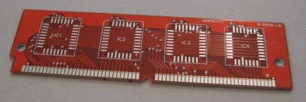
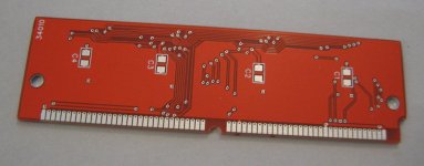
Unfortunately I have been battling a stomach bug of some kind all week (I won't go into any detail! haha) and it's still attacking me, so I'm not sure when I'll get around to assembling one to make sure they work. But at first glance, they look very nice! They also fit into the IIci's ROM SIMM slot great as far as I can tell.
Excellent turnaround time. Order was placed the night of 9/5/2011, I got the shipping notice 9/13/2011, and the package arrived 9/23/2011. Like most others whose reviews I read, I got 12 boards instead of 10 and they added a few numbers of their own to the silkscreen (I added my order number to the silkscreen too, because their instructions said to do that). They are actually about 50 mils thick instead of 47, but that's still perfect. I have to say I'm pretty darn impressed with Seeed Studio! Thanks again for letting me know about them, bigmessowires. Definitely awesome!
Anyway, once I'm feeling better I will start doing the fun stuff with these PCBs!
And then once it's all good, I'll get some skull versions of the board made! Haven't had any time to look at the LED stuff yet, but that can wait until I know that this board works.
It really depends on what I'm looking for. If all I'm looking for is the startup chime, I already have ROM maps from Apple of several of the various II series (but not all! -- II, IIfx, IIci, IIsi, and IIvi) which will directly show me where the code is. But if we're looking to see just how similar two ROMs are, it would probably be awesome to have some kind of app that figured out the differences.
I actually have no idea if this is a standard thing that reverse engineering types do. I would imagine it would be a very useful tool to have. To be completely useful, I'm thinking it would need to be integrated into a disassembler to help determine what's code and what's data -- this would probably help some kind of algorithm to know what chunks to compare between the two files. Also it would need to know to ignore jump/branch targets when comparing two chunks of code because as code is rearranged in the ROM the offsets to jump to would change. This is true even though the ROM is position-independent because the relative jump offset would still be different as code was moved around/inserted/deleted in ROM. Who knows--maybe IDA Pro already has something like that?With a comparative parser (?), you could identify blocks of instructions that are identical, even when stored at different address spaces on the four ROM samples.
Using a more complicated parser, you could identify blocks of instructions with a variable scale of change differential in similar blocks of instructions.
Kinda like running a PhotoShop Filter on sets/subsets of ROM instructions? :?:
If this is a standard feature of de-compiling (?) software a/o S.O.P. for such processes, forgive my ignorance, but I just HAD to ask! :
The most basic example would be a binary diff tool, but that would be very, very simple and probably wouldn't give much useful information -- for instance it doesn't know how to ignore jump targets. It would take quite a bit of effort, I'm guessing, to make a "ROM diff" utility as described above. It would probably be quicker just to manually inspect the ROMs
but I do have to say it would still be useful, especially if you could just use it to play around and see how different the LC 520 ROM is from the LC III ROM for example. It's probably not something I have any time to work on though.Anyway, it's great that you posted this "bump" today because...
The boards have arrived!
Unfortunately I have been battling a stomach bug of some kind all week (I won't go into any detail! haha) and it's still attacking me, so I'm not sure when I'll get around to assembling one to make sure they work. But at first glance, they look very nice! They also fit into the IIci's ROM SIMM slot great as far as I can tell.
Excellent turnaround time. Order was placed the night of 9/5/2011, I got the shipping notice 9/13/2011, and the package arrived 9/23/2011. Like most others whose reviews I read, I got 12 boards instead of 10 and they added a few numbers of their own to the silkscreen (I added my order number to the silkscreen too, because their instructions said to do that). They are actually about 50 mils thick instead of 47, but that's still perfect. I have to say I'm pretty darn impressed with Seeed Studio! Thanks again for letting me know about them, bigmessowires. Definitely awesome!
Anyway, once I'm feeling better I will start doing the fun stuff with these PCBs!
And then once it's all good, I'll get some skull versions of the board made! Haven't had any time to look at the LED stuff yet, but that can wait until I know that this board works.
Woohoo!
Get well soon, feel better and then get to solderin' those beautiful lil' boards, comrade! :approve:
Well, I've started feeling a lot better today, so naturally this afternoon I sat down and put one of them together. I ended up destroying the center plastic plate on the sockets so I could reach the pins. I also ended up having to cut off the alignment pegs from the bottom of the sockets because I accidentally ordered sockets that had alignment pegs!
Haven't tested it yet because I rinsed it off with water to clean off the flux and I'm going to let it dry for a while. I have done some continuity checking and everything seems to be connected right. Here's what it looks like (don't laugh too much at my surface mount soldering , especially on the back side...even those "big" 1206 capacitors are TINY!):
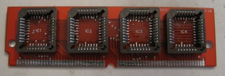
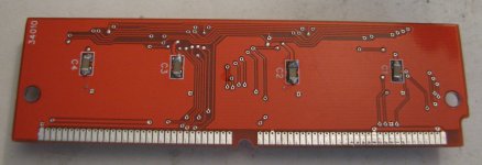
Haven't tested it yet because I rinsed it off with water to clean off the flux and I'm going to let it dry for a while. I have done some continuity checking and everything seems to be connected right. Here's what it looks like (don't laugh too much at my surface mount soldering
, especially on the back side...even those "big" 1206 capacitors are TINY!):
I see solder bridges along the top row of pins on both IC2 and IC3. Should be easy to fix with some solder wick.
I'm looking forward to seeing this in action!
I'm looking forward to seeing this in action!
Hey, thanks for pointing those out--I noticed those when I soldered, but those pins are connected together on the board anyway in order to pull the write enable pin high (the other pin is VCC), so I just left the bridges there. I forgot to mention that I think the solder bridged because there is a via between the pins.
I think the solder bridged because there is a via between the pins.
Way cool! :approve:
Will these boards work as IIfx ROM SIMMs?
Will these boards work as IIfx ROM SIMMs?
Ah, that makes sense. Then you're almost ready to go!
Drumroll:
TATATATATATATATATATATATATATATATATATATATATATATATATA
TATATATATATATATATATATATATATATATATATATATATATATATATA
(waits expectantly)
Drumroll:
TATATATATATATATATATATATATATATATATATATATATATATATATA
TATATATATATATATATATATATATATATATATATATATATATATATATA
(waits expectantly)
It should work in a IIfx as well as all the other II series that have a ROM SIMM socket, as well as the SE/30. The IIsi may have a slightly different pinout that I'll have to change in my future revision -- one of the address lines is marked as VCC in GTTMFH2E, but the IIsi devnote calls it another address line. I hooked it up as VCC on my pinout, but I should probably just leave it not connected instead.
I just tried my SIMM in my other IIci (which boots fine from the onboard ROM), and...nothing happened other than the fan spinning up.
The ROM SIMM jumper is removed, so that's not the problem. This is gonna be a very tough one to troubleshoot...I also removed all four of the chips and reseated them (eeek, those PLCC sockets are annoying, on-chip programming would be much nicer). It could be that I have them reversed, so I'll keep playing around with it.
Edit: Nope, not reversed either -- well, it doesn't work either way. So I guess the next step is to check the continuity of EVERY SINGLE PIN...gahhhhh
Edit2: I've checked the continuity of each pin to its corresponding SIMM contact, although I did not check for shorts on each pin. I also tried it in my hacked IIci with the same bad results. The possibilities I can think of:
I just tried my SIMM in my other IIci (which boots fine from the onboard ROM), and...nothing happened other than the fan spinning up.
The ROM SIMM jumper is removed, so that's not the problem. This is gonna be a very tough one to troubleshoot...I also removed all four of the chips and reseated them (eeek, those PLCC sockets are annoying, on-chip programming would be much nicer). It could be that I have them reversed, so I'll keep playing around with it.
Edit: Nope, not reversed either -- well, it doesn't work either way. So I guess the next step is to check the continuity of EVERY SINGLE PIN...gahhhhh
Edit2: I've checked the continuity of each pin to its corresponding SIMM contact, although I did not check for shorts on each pin. I also tried it in my hacked IIci with the same bad results. The possibilities I can think of:
- One or more of the chip contacts is not making contact with the socket properly (very likely, PLCC sockets are pretty flaky)
- Intermittent solder joint on one of the PLCC sockets' contacts
- I got one of the pins wrong on my layout so it's connected to the wrong pin on the chip
- Two of my pins are shorted together
- The IIci's pinout does not match what GttMFH2E says
IT WORKS!!!!
I accidentally had D23 shorted to chip select (you can kind of see it in my picture on IC3, right side, two bottom pins). I cut the short out of there with an X-Acto knife, and shazam! It worked! (I also had the chips backwards ;-) )
I haven't yet had a chance to test the larger ROM capacity, but I was able to get my other IIci to boot with the custom chime.
The reasoning for the chips being backwards is that since the 680x0 is big-endian, the most significant byte out of each 4-byte word is the FIRST byte. This means that the very first byte in ROM is the most significant byte of the first 4-byte word, so it should be on D24 through D31. Seems kind of bass-ackwards, but it makes complete sense now that I think about it. So IC4 contains bytes 0, 4, 8, etc., IC3 contains bytes 1, 5, 9, etc., IC2 contains bytes 2, 6, 10, etc., and IC1 contains bytes 3, 7, 11, etc.
I accidentally had D23 shorted to chip select (you can kind of see it in my picture on IC3, right side, two bottom pins). I cut the short out of there with an X-Acto knife, and shazam! It worked! (I also had the chips backwards ;-) )
I haven't yet had a chance to test the larger ROM capacity, but I was able to get my other IIci to boot with the custom chime.
The reasoning for the chips being backwards is that since the 680x0 is big-endian, the most significant byte out of each 4-byte word is the FIRST byte. This means that the very first byte in ROM is the most significant byte of the first 4-byte word, so it should be on D24 through D31. Seems kind of bass-ackwards, but it makes complete sense now that I think about it. So IC4 contains bytes 0, 4, 8, etc., IC3 contains bytes 1, 5, 9, etc., IC2 contains bytes 2, 6, 10, etc., and IC1 contains bytes 3, 7, 11, etc.
Woohoo! ;D :approve:
NICE!!! Congratulations!
How did you figure out the chips were byte-reversed? Just staring at the schematics again while looking for explanations? That could have taken a long time to realize, but you found it quickly.
Let the crazy ROM hacking begin!
How did you figure out the chips were byte-reversed? Just staring at the schematics again while looking for explanations? That could have taken a long time to realize, but you found it quickly.
Let the crazy ROM hacking begin!
Will the revision have the pirate?
Thanks! I already had the hacking going before by socketing the DIPs, but now the REAL hacking can begin since it'll be WAY easier to change the ROMs without yanking out the hard drive and floppy drive, and it'll be way easier for everyone else to play around with the hacking too.
Speaking of others, I have 11 more boards here (with no jolly roger yet). Who all is interested in one? You'll still need an EEPROM burner to put programs on the chips until I can figure out how to make it fully programmable over USB or whatever -- or even a programmer board with a 64-pin SIMM socket would be great, but I can't find 64-pin SIMM sockets anywhere (plus I'd have to bring out the write enable line somehow). Once I get the jolly roger stuff finished I'll do a bigger order from Seeed (50 boards perhaps?).
But until then, is anybody interested in boards? I'd be happy to send out bare boards to anyone for $2.90 (1/12 of my PCB order cost) plus the cost of shipping Like I said, the SIMM should work in any of the II series Macs that have a ROM SIMM socket with the exception of the IIsi but that can be fixed by cutting a trace, and also the SE/30. That cost will go down once I order a bigger quantity. You can provide your own sockets, capacitors, EEPROMs, and soldering in that case.
For an assembled one, I'd be happy to solder sockets and capacitors onto the boards but I'll have to charge a small amount more than just the parts cost because my time is worth *something* You'll still need an EEPROM burner to flash the chips though. The sockets and capacitors cost about $4 in total to put on the board, the board is about $3, and I think it's fair to charge about $8 for my time, so I'm looking at $15 plus shipping for an assembled SIMM. Any objections? That doesn't count the EEPROMs which you can get yourself from Mouser or another distributor like that for about $2 a pop. You'll probably want a PLCC extractor tool too. Anyway, I will reserve a board for tt just in case because I know he was interested way back when...let me know for sure tt.
And those will also have the fix so they will work unmodified in the IIsi.
I already had the hacking going before by socketing the DIPs, but now the REAL hacking can begin since it'll be WAY easier to change the ROMs without yanking out the hard drive and floppy drive, and it'll be way easier for everyone else to play around with the hacking too.Speaking of others, I have 11 more boards here (with no jolly roger yet). Who all is interested in one? You'll still need an EEPROM burner to put programs on the chips until I can figure out how to make it fully programmable over USB or whatever -- or even a programmer board with a 64-pin SIMM socket would be great, but I can't find 64-pin SIMM sockets anywhere
(plus I'd have to bring out the write enable line somehow). Once I get the jolly roger stuff finished I'll do a bigger order from Seeed (50 boards perhaps?).But until then, is anybody interested in boards? I'd be happy to send out bare boards to anyone for $2.90 (1/12 of my PCB order cost) plus the cost of shipping
Like I said, the SIMM should work in any of the II series Macs that have a ROM SIMM socket with the exception of the IIsi but that can be fixed by cutting a trace, and also the SE/30. That cost will go down once I order a bigger quantity. You can provide your own sockets, capacitors, EEPROMs, and soldering in that case.For an assembled one, I'd be happy to solder sockets and capacitors onto the boards but I'll have to charge a small amount more than just the parts cost because my time is worth *something*
You'll still need an EEPROM burner to flash the chips though. The sockets and capacitors cost about $4 in total to put on the board, the board is about $3, and I think it's fair to charge about $8 for my time, so I'm looking at $15 plus shipping for an assembled SIMM. Any objections? That doesn't count the EEPROMs which you can get yourself from Mouser or another distributor like that for about $2 a pop. You'll probably want a PLCC extractor tool too. Anyway, I will reserve a board for tt just in case because I know he was interested way back when...let me know for sure tt.Well I knew it was either going to be 1-2-3-4 or 4-3-2-1, so I just tried both combinations after I fixed the short. I had already known about the interleaving going on when I was hacking with the DIPs, but I never paid attention to which data lines each chip was connected to. Then I wanted an explanation for why it was the way it was, so that's when I sat down and thought about it
The 12 boards I have now do not have the pirate, but the next PCBs I order from Seeed will. I'll probably go for the red silkscreen again too
And those will also have the fix so they will work unmodified in the IIsi.KAWABUNGAAAAAAAAAAAAAAAA!!!!!!!!!!!!!!!!!!!!!!!!!!!!!!!!!!!!!!! [
 ] ]'>
] ]'>The Pirate's of Ancient Macintosh Modification version really ought to be BLACK!
. . . w/RED LED(s)! }
IMHO, of course!
If you want vinyl graphics for the Proto-Boards, I'll fire up the 'ole 40" vinyl cutting/inkJet plotter!
BTW, put me down as your first customer, I'd also suggest that you order the ROMs for the two run set if you can get a price break. Shipping the entire assembly w/unburned ROMs should be no problem and it will cut way down on end user cost by cutting out the second round of shipping costs from Mouser & Company.
If inventory cost will be problematic, just ask the PoAMM gang!
edit: a transparent black Silk Screen would be asking a LOT!!!!
p.s. TEN freakin' pages/225 replies and 2885 views . . .
. . . for a new recruit's very first post! Congrats, buddy! :approve:
The board looks beautiful! Great work. Thanks so much for thinking of me, yes I would like to buy a board, I will send you a PM. :b&w:
I'd love to buy one with the pirate on it. I wanna change my startup sound to the "Arrrr!" from Pirates! Gold, and put a Pirate IIci for the boot icon. :lol:
Black PCBs are awesome, but Seeed doesn't do themThe Pirate's of Ancient Macintosh Modification version really ought to be BLACK!. . . w/RED LED(s)! }
IMHO, of course!
 They do have white soldermask with black silkscreen as an option, though...
That's pretty cool! I have to admit though that I'm not very versed in this stuff -- how do you put vinyl graphics onto a PCB?
Good idea! I see what you mean about taking away the shipping cost from Mouser, so I'll go that route instead. This will add about $8 to the cost of the assembled board, maybe a buck less if I can do a bigger order of chips. So a total of $23 unless I can discount it more. Who is PoAMM? I'm not sure that inventory cost will be necessarily problematic, but I don't want to order 100 ROM chips when I only have 3 people interested ;-)BTW, put me down as your first customer, I'd also suggest that you order the ROMs for the two run set if you can get a price break. Shipping the entire assembly w/unburned ROMs should be no problem and it will cut way down on end user cost by cutting out the second round of shipping costs from Mouser & Company.
If inventory cost will be problematic, just ask the PoAMM gang!
Transparent black?? I have nooo idea how that could even be done!
Thank you, thank you! It's been a blast doing this!
Awesome, thanks!!
;D that will rock! I'll keep you in mind as soon as I get new boards with your awesome pirate drawing (and hopefully LED(s))!
Pirates of Ancient Macintosh Modification [
] ]'>
I just got done testing out the SIMM with the SST39SF040, one of Microchip's flash chips which they did not spin off to Greenliant. It's a 4 megabit (512 kilobyte) chip, so with four of them I have 2 megabytes of ROM space available. That's the largest size that will fit in my SIMM. Luckily, everything worked A-OK! The checksum only applies to the first 512K of the ROM. I used most of the remaining 1.5 MB to contain a very large chunk of the Super Mario Bros song, and set it as the startup chime. It goes on for over a minute before the system finally boots
Here's a video of it (I show off the SIMM at first):
Each chip takes several minutes to program in my programmer. I guess once I start getting up that high in capacity it isn't too surprising. In case anyone is wondering, I'm using a Sivava Willem programmer board on a Windows 7 computer with a PCI Express parallel port card. It's not officially supported past Windows XP, but I found lots of info online about it and actually ended up adapting other people's DLLs to get it to work on mine. I have a blog post about that endeavour here if anyone else needs to get it running.
Here's a video of it (I show off the SIMM at first):
Each chip takes several minutes to program in my programmer. I guess once I start getting up that high in capacity it isn't too surprising. In case anyone is wondering, I'm using a Sivava Willem programmer board on a Windows 7 computer with a PCI Express parallel port card. It's not officially supported past Windows XP, but I found lots of info online about it and actually ended up adapting other people's DLLs to get it to work on mine. I have a blog post about that endeavour here if anyone else needs to get it running.
Wow, that is awesome potential (great choice of musical score). It makes me wonder if a slim version of OS 6/7 could be added to the ROM like how the Mac Classic has a hidden boot disk image that can be activated by holding down some keys.
How the Classic's ROM disk image is implemented would probably require dissembling the ROM. I did find the following which sheds a little light on the subject:
http://www.eeggs.com/items/534.html
http://www.eeggs.com/items/534.html
Actually, the ROM Disk in the Classic was a secret project that only a couple engineers knew about until it shipped. The reason it was added was because the ROM chip was 512K (16x256K), the original SE ROM (which this was based on) only required 256K bytes, and the engineer who did it had some extra night cycles to spend doing something fun. It was not part of any official Apple project. So this free 256K, plus around 50K from the SE photos, was used for the disk image (which was compressed) and ROM Disk driver. Apple-Talk was added as well, and the ability to save some info in PRAM. This enabled it to remember a network startup disk (plus any password required), and also saved the app name on the network drive and auto launch it (not sure if this was ever mentioned before
COOL! 
I just LOVE tangential topic tidbits, the most interesting information turns up! :approve:
If anyone has a link to a Black PCB, please post it, my sign making/graphic design addiction just kicked back in and I'm wondering how we can use every color/color tone available on the final PCB design to enhance the Pirates of Ancient Macintosh Modification LOGO! [}] ]'>
Post a dead on shot of the Jolly Roger side of your PCB and I'll do a little playing around in GraphicConverter.
Better yet, if you can also export some kind of Graphics or CAD file from your PCB layout of the Jolly Roger PCB design, email that and the pic to me! }
I just tested my IIfx ROM SIMM in my IIsi without damage to either, but without a boot chime from the IIsi/IIfx ROM SIMM. :-/
Maybe I can do a jumper hack or a reversible bared trace hack to my IIfx ROM SIMM to test out your theory. }
You might want to add provision for a three hole (on-off) jumper header to your Jolly Roger SIMM with a triangular/bow tie cut point for a less complicated, but readily reversible IIsi modification. Soldering a jumper wire to fix the cut would be the simple reversing procedure, while soldering in the three header jumper would make the mod process quickly reversible. [] ]'>
I just LOVE tangential topic tidbits, the most interesting information turns up! :approve:
Bad choice of terms, substitute translucent for transparent. If Black PCBs look cool, the soldermask MUST be translucent to show the traces.Transparent black?? I have nooo idea how that could even be done!
If anyone has a link to a Black PCB, please post it, my sign making/graphic design addiction just kicked back in and I'm wondering how we can use every color/color tone available on the final PCB design to enhance the Pirates of Ancient Macintosh Modification LOGO! [}
] ]'>Post a dead on shot of the Jolly Roger side of your PCB and I'll do a little playing around in GraphicConverter.
Better yet, if you can also export some kind of Graphics or CAD file from your PCB layout of the Jolly Roger PCB design, email that and the pic to me! }
. . . and which trace might that be? :?:
I just tested my IIfx ROM SIMM in my IIsi without damage to either, but without a boot chime from the IIsi/IIfx ROM SIMM. :-/
Maybe I can do a jumper hack or a reversible bared trace hack to my IIfx ROM SIMM to test out your theory. }
You might want to add provision for a three hole (on-off) jumper header to your Jolly Roger SIMM with a triangular/bow tie cut point for a less complicated, but readily reversible IIsi modification. Soldering a jumper wire to fix the cut would be the simple reversing procedure, while soldering in the three header jumper would make the mod process quickly reversible. [
] ]'>
A suggestion: Name it ProAMM (like Pro/Amateur). Pirates of Ancient Macintosh Modification.
I'd like to buy one of the original boards if you're selling them. I can use it to test my soldering skills so I don't muck up the Pirate Edition.
Since the best price for end users will be the option of buying all parts from you for a single shipping cost anyway, I'd suggest assembly be included as well.
Amortize the cost of a Solder Paste Mask and a decent toaster oven processing unit across the first two runs. Include parts, paste, your assembly/testing/debugging and handling time, etc. for a final, ready for programming, SIMM & ROMs deal. The only variable would be shipping levels for the outer two states and foreign countries.
That way nobody need bork a socket while removing the backing plate, you avoid that extra labor for removal for basic assembly.
You could even farm out the assembly/shipping work to another hacker (NOT ME!!!!!!!!!!!!!!!!!) and concentrate on having more ROM hacking fun!
Unless you'd like the extra toy(s), of course! :approve:
Amortize the cost of a Solder Paste Mask and a decent toaster oven processing unit across the first two runs. Include parts, paste, your assembly/testing/debugging and handling time, etc. for a final, ready for programming, SIMM & ROMs deal. The only variable would be shipping levels for the outer two states and foreign countries.
That way nobody need bork a socket while removing the backing plate, you avoid that extra labor for removal for basic assembly.
You could even farm out the assembly/shipping work to another hacker (NOT ME!!!!!!!!!!!!!!!!!) and concentrate on having more ROM hacking fun!
Unless you'd like the extra toy(s), of course! :approve:
Well, I have some solder paste on the way. Even if I just use an iron, it may help with assembling the boards. I also got a really weird bent shaped tip for my iron, and I'm hoping it might make it possible to reach the leads. It's pretty tough, though -- once I come in contact with the plastic it starts melting pretty fast. So having someone with better tools assemble them might be the better answer. I'm sure you're also laughing at my soldering job on the capacitors on the back side I know I can do a much better job than that, but I was in a hurry to get it working and try it out
I'd like to be able to preserve the bottom plastic plate so you can't push the chips too far down--once they go too far, it's a pain to remove them with the PLCC extractor tool. I've been just barely pushing the chips in, then turning the board upside down and pushing on it, so the chips end up flush with the top of the socket. That seems to work well.
The oven thing may work, and in fact, I just recently ordered a cheap convection oven online, but I'm a little worried about melting the plastic sockets. Plus, I haven't decided whether I'm going to use it for pizza or PCBs yet ;-)
My plan is to allow anyone who just wants the bare board to get it that way if they want it, and otherwise fully assembled. I suppose it makes sense to include parts with the bare board too though, you're right...
I know I can do a much better job than that, but I was in a hurry to get it working and try it out I'd like to be able to preserve the bottom plastic plate so you can't push the chips too far down--once they go too far, it's a pain to remove them with the PLCC extractor tool. I've been just barely pushing the chips in, then turning the board upside down and pushing on it, so the chips end up flush with the top of the socket. That seems to work well.
The oven thing may work, and in fact, I just recently ordered a cheap convection oven online, but I'm a little worried about melting the plastic sockets. Plus, I haven't decided whether I'm going to use it for pizza or PCBs yet ;-)
My plan is to allow anyone who just wants the bare board to get it that way if they want it, and otherwise fully assembled. I suppose it makes sense to include parts with the bare board too though, you're right...
Lets see if trag or techknight chime in with the skinny on any possible Dali-esque Consequences for Plastic Sockets when using the Toaster Oven Method.
Will a convection oven even work for solder paste reflow?
As a novice level wielder of the soldering iron . . .
. . . I've been doing it a tad better than badly, since the first application of my wood burning iron . . .
. . . to Plastic Model DC Motor Connections, something on the order of 45-50 years ago! [:I] ]'>
I think it's probably best to let you do the job!
That video is just too awesome, I've got a quick question.
I've noticed that the 2 Nubus Power Macs I have (6100 and 7100) have removable ROM DIMMS, would it be possible to do a similar hack to change their startup sounds?
I don't know if there is any documentation on the later machines, but it seems to me that it could possibly be done.
I would look into it but I'm very educated in software or hardware hacking like this.
Anyway keep up the great work dougg :ii:
I've noticed that the 2 Nubus Power Macs I have (6100 and 7100) have removable ROM DIMMS, would it be possible to do a similar hack to change their startup sounds?
I don't know if there is any documentation on the later machines, but it seems to me that it could possibly be done.
I would look into it but I'm very educated in software or hardware hacking like this.
Anyway keep up the great work dougg :ii: