

Thread
PowerBook Duo battery replacement
I built the AAA Duo battery! And it was a complete failure. :-(
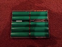
I decide to use a Type I battery as the "donor" instead of a Type III, since the newer AAA cells I bought are closest to the Type I battery capacity. When I sliced open my Type I battery, I was surprised to see that it's very different from the Type III. It's got full-sized AA cells, in a 5x2 configuration:
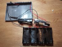
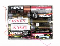
I pulled everything apart, and started soldering AAA holders. This was trickier than I was expecting. I ended up with four two-cell AAA holders, two more two-cell AAA holders cut in half to make two one-cell holders, and one of the two original fuses, all in series. I ended up omitting the second fuse, since it didn't look like there would be space for it. Here's what the wiring job looked like, before I started cramming it all back inside the original battery case:
Four two-cell AAA holders just barely fit side-by-side along the battery's long dimension, leaving less space than I'd expected for the last two batteries, the fuse, the thermistor, and the wires. It was a major pain in the butt, involving a lot of cutting, filing, and re-arranging. It was somewhere during this part that the fun ended, and I started to get annoyed. After way too long, I finally got something half-way serviceable:
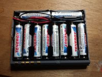
I found it impossible to get the battery cover back on completely. Whether because the AAA holders were just a little too thick, or because the ragged cuts I made when slicing open the battery cover didn't stitch together cleanly, or something else, I'm not sure. No matter what I did, the rebuilt battery was about 1 mm or so thicker than the original.
I measured the voltage at the exterior battery terminals at 12.4V, which is just about right.
Then I belatedly realized there's no good way to reattach the cover's top and bottom, other than glue or tape. I used a layer of packing tape, but it didn't adhere to the battery cover plastic very well, and it tended to shear off when I put the battery into the Duo. Eventually I removed all the tape, and just stuffed the battery sandwich straight into the Duo, relying on the body of the Duo to hold everything together. It was a very tight fit.
The moment of truth: I put the battery in the Duo 250, hit the power switch, and... nothing. I put it in the Duo 230, hit the power switch, and nothing.
I put the Duo 230 with the rebuilt battery into the Dock, and booted up. It recognized the battery and said it was 50% charged. But after only 12 minutes, it had reached full charge. :?: I shutdown, took the Duo out of the Dock, and tried booting from the battery once again. This time it booted up! But immediately after booting, it reported that the battery was only 75% charged, not full. Six minutes later I got the "reserve power" warning. After 14 minutes the Duo shut down completely. So much for battery life.
TL;DNR version: everything turned out like %@. I'm not really sure why the battery performed so poorly, but even if it had worked great, it was so awkward that it wouldn't have been very useful anyway.
Trash, I think you're on a better track with those AA cells in your FrankenPack. I think the NiMH cells you've got there should be fine, but given how well my battery rebuild went, you probably shouldn't trust my opinion on that.
I decide to use a Type I battery as the "donor" instead of a Type III, since the newer AAA cells I bought are closest to the Type I battery capacity. When I sliced open my Type I battery, I was surprised to see that it's very different from the Type III. It's got full-sized AA cells, in a 5x2 configuration:
I pulled everything apart, and started soldering AAA holders. This was trickier than I was expecting. I ended up with four two-cell AAA holders, two more two-cell AAA holders cut in half to make two one-cell holders, and one of the two original fuses, all in series. I ended up omitting the second fuse, since it didn't look like there would be space for it. Here's what the wiring job looked like, before I started cramming it all back inside the original battery case:
Four two-cell AAA holders just barely fit side-by-side along the battery's long dimension, leaving less space than I'd expected for the last two batteries, the fuse, the thermistor, and the wires. It was a major pain in the butt, involving a lot of cutting, filing, and re-arranging. It was somewhere during this part that the fun ended, and I started to get annoyed. After way too long, I finally got something half-way serviceable:
I found it impossible to get the battery cover back on completely. Whether because the AAA holders were just a little too thick, or because the ragged cuts I made when slicing open the battery cover didn't stitch together cleanly, or something else, I'm not sure. No matter what I did, the rebuilt battery was about 1 mm or so thicker than the original.
I measured the voltage at the exterior battery terminals at 12.4V, which is just about right.
Then I belatedly realized there's no good way to reattach the cover's top and bottom, other than glue or tape. I used a layer of packing tape, but it didn't adhere to the battery cover plastic very well, and it tended to shear off when I put the battery into the Duo. Eventually I removed all the tape, and just stuffed the battery sandwich straight into the Duo, relying on the body of the Duo to hold everything together. It was a very tight fit.
The moment of truth: I put the battery in the Duo 250, hit the power switch, and... nothing. I put it in the Duo 230, hit the power switch, and nothing.
I put the Duo 230 with the rebuilt battery into the Dock, and booted up. It recognized the battery and said it was 50% charged. But after only 12 minutes, it had reached full charge. :?: I shutdown, took the Duo out of the Dock, and tried booting from the battery once again. This time it booted up! But immediately after booting, it reported that the battery was only 75% charged, not full. Six minutes later I got the "reserve power" warning. After 14 minutes the Duo shut down completely. So much for battery life.
TL;DNR version: everything turned out like %@.
I'm not really sure why the battery performed so poorly, but even if it had worked great, it was so awkward that it wouldn't have been very useful anyway.Trash, I think you're on a better track with those AA cells in your FrankenPack. I think the NiMH cells you've got there should be fine, but given how well my battery rebuild went, you probably shouldn't trust my opinion on that.
Heh! Which kinda like why I started out with a pre-shattered BatPack for the hack! Sorry to hear yours didn't turn out so well, I wonder if the VST Conditioning Charger might do the trick for yours?
Pics coming up shortly . . .
Pics coming up shortly . . .
Sorry about the mongoid pics, gang. GraphicConverter is acting up on the Pismo500 and I don't have time to sort it out tonight, But I'll do so and swap appropriately sized pics in for these ASAP.
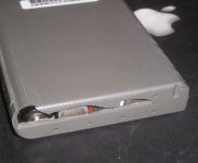
All ten cells fit in just fine after excising all the ribs that were in the way. The cells have room to do a bit of the shake, rattle and roll in the X,Y and Z axes.
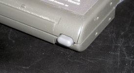
The button with the gummi-spring works! When I was expressing my concerns over the heat tolerance of gummi bears and their conductivity in a molten state to a friend, he suggesting using a marshmallow . . . so of course I just had to try it, they have interesting phase change and carbonizing characteristics under high thermal loading.
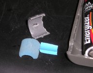
Whatever, I decided to sweep up my work area and I found the rubber grip tube from a pen or ever-sharp, so I finished hacking it together right then and there while I had some downtime. [] ]'>
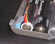
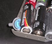
I took a rattail file, some other goodies and all the parts for the FrankenPack prototype to work after lunch. That battery case makes spindly plastics seem like wrought Iron! I guess the waste heat from charge/discharge cycles bakes all the plasticizers out of the stuff. Anyway, don't use knives or Plexi Scribes for removing the rib obstacles. That's definitely Dremel work.
I have a halfway borken slide from the better batpack, so I took the rubber bands off the FrankenPack's shell, slid the slide on and tried a dry run installing it in a Duo. The FrankenPack fits, the spongy-spring works, though I need to find spring material just a bit better suited to the task . . .
. . . but the concept is well proven. It's off to CrapShack ASAP! [}] ]'>
All ten cells fit in just fine after excising all the ribs that were in the way. The cells have room to do a bit of the shake, rattle and roll in the X,Y and Z axes.
The button with the gummi-spring works! When I was expressing my concerns over the heat tolerance of gummi bears and their conductivity in a molten state to a friend, he suggesting using a marshmallow . . . so of course I just had to try it, they have interesting phase change and carbonizing characteristics under high thermal loading.
Whatever, I decided to sweep up my work area and I found the rubber grip tube from a pen or ever-sharp, so I finished hacking it together right then and there while I had some downtime. [
] ]'>I took a rattail file, some other goodies and all the parts for the FrankenPack prototype to work after lunch. That battery case makes spindly plastics seem like wrought Iron! I guess the waste heat from charge/discharge cycles bakes all the plasticizers out of the stuff. Anyway, don't use knives or Plexi Scribes for removing the rib obstacles. That's definitely Dremel work.
I have a halfway borken slide from the better batpack, so I took the rubber bands off the FrankenPack's shell, slid the slide on and tried a dry run installing it in a Duo. The FrankenPack fits, the spongy-spring works, though I need to find spring material just a bit better suited to the task . . .
. . . but the concept is well proven. It's off to CrapShack ASAP! [}
] ]'>
Nice! It looks like that worked out really well. Is there still space for the fuse, thermistor, ID chip, etc? Have you tried it in your Duo yet?
Here are some battery cell reference photos. The Type I and Type III cells are totally different. Type I cells look like the same dimensions as a standard AA, but without the nub on the positive end. Type III cells are significantly shorter and wider. Maybe they're actually A cells, not AA's?
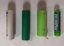
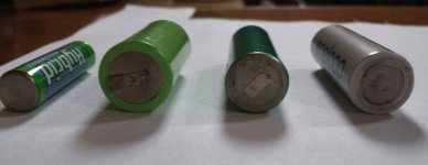
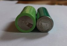
THX, but NOPE to the max there, big. I'm waiting for reports from you electron pusher types on what needs to be done before going there. I much prefer taking the KISS approach outlined earlier. I'm opting for charging my "off the shelf" cells four at a time in the blister-pack charger I got with the first set, forgoing in-Duo charging altogether. As for testing, I'll be doing that out-of-Duo as well, I'll dig up the pic of my Minimalist Duo Testbed, we're talking alligator clip/wire methodology for that evolution. [
] ]'>However, that would be affirmatory on the available cubic question, there's adequate, if not plenty of room so spare on all three axes for electronics tomfoolery.
Again, sorry for your disappointment, but you've only just learned one of the "ways not to build a light bulb." ;D
Not the first way either! ___?___ already reported that overheating from soldering tab to contact is harmful to tabbed cells. Bunsen says building a spot welder for this application ought to be easy enough. With a tack weld hole drilled in the tabs, power requirements of the unit ought to be appreciably diminished.
But I'd hold off on that declaration of complete failure! I really like your AAA holder approach. On which axis is you cubic limitation? Looks like it must be vertical, but then you couldn't have gotten it together at all. dunno, let me know if it was X, or Y, it's not really the time for guesswork.
In terms of closing the case up sans glue, It lookss to me that you have plenty of space between cells at the joints between the battery holders. Four flat head machine screws and standoffs appear to the best solution. My nylon standoffs aren't drilled and tapped all the way through due to being M/F, but one of the two lengths I have on hand appear be easily modified to exactly the right length, I'll likely use the shorter version so you can do your height adjustment with washers. Drilling through my nylon standoffs with a 4/40 tap thread bit should yield a perfect hole on the male end and four flat head plastic thread screws on the permanently attached side fulfill the balance of your requirements. Give 'er a look over and let me know what you think, I've just decided to use this KISS aproach for the FrankenBat. No hinging and slide clipping necessary in that case, I can just build the Bride of FrankenPack for that second set of toy batteries.
It should be easy enough to use a half round bastard file to give them a "bow tie" profile for the thinnest space between cells. using the edge of a flat bastard on the sides of the adjoining holders for the thin center spot of the "bow tied" standoffs will be child's play. Locate four places where the deepest point of the centers of the humped cell divider ribs align with the joints of your AAA holders. and four modified standoffs will go bi-coastal in a heartbeat (to the Nth) for batpack jointery.
It also looks like they moved the entire backside of the contact section of the pack wrap right around to a flat edged topside casting?
I was so tired last night and frustrated from fighting with that GraphicConverter install that I totally overlooked your report on the 2x5 AA Cell config of that type III battery. Could you post some pics of the latch latch button implementation? THX much for those cell pics, I was searching nimh +tabbed +cells last night and found the 2/3 A cells, I checked this morning an realized that that's what is in the supercharged extended BTI batpack, which explains all the plastic posicle stick spacers I found on the sides of the cell array when I cracked the case.
I forgot that I have a standard BTI battery on hand as well. I can tell it uses the same layout as the FATbarH pattern in the Apple Battery Types I and II.
Aha! That was beachycove report on p.1 about soldering tabs being the first way not to build a lightbulb. THX, beachy!
It just occurred to me that a Duo Battery Pack might be a wonderful first Rapid Prototyping project for someone experienced in the art of 3D CAD/CAM file production.
Does anyone know the shrinkage/expansion/dimensional stability characteristics for epoxy casting? We've had reports on resin casting size limitations, I wonder how the batpack compares to the quoted max size limit.
Dunno, still spitballin' up to here.
_________ Serious Stuff __________
Can anyone tell me to which contacts on the Minimalist Duo I should be attaching my negative and positively charged alligator clips?
Should I be putting a current limiting resistor on the Negative(?) jumper cable?
I'm guessing that answer will be a YES, so what value of resistance would I need for the FrankenPack's set of ten 2450mAh AA Cells?
It just occurred to me that a Duo Battery Pack might be a wonderful first Rapid Prototyping project for someone experienced in the art of 3D CAD/CAM file production.
Does anyone know the shrinkage/expansion/dimensional stability characteristics for epoxy casting? We've had reports on resin casting size limitations, I wonder how the batpack compares to the quoted max size limit.
Dunno, still spitballin' up to here.
_________ Serious Stuff __________
Can anyone tell me to which contacts on the Minimalist Duo I should be attaching my negative and positively charged alligator clips?
Should I be putting a current limiting resistor on the Negative(?) jumper cable?
I'm guessing that answer will be a YES, so what value of resistance would I need for the FrankenPack's set of ten 2450mAh AA Cells?
I forgot the most important question of allI :
Do I have a volunteer for the reverse engineering of BTI's PIC based Intelligent batpack implementation?
Unfortunately I got my first lesson on wire integrity preservation cracking that puppy. Fortunately it was the assumption that I was avoiding a flex circuit as illustrated by bat hackers past. unfortunately, BTI used real wires straddling the seam of the pack. Thankfully they're very ournicely color coded!
My gut tells me that cloning this smart battery board could be the answer to all our NiMH mAh variation recelling woes.
My hope is that a few bits in the ROM section of the PIC hold that variable quantity.
There's PLENTY of room for a seeded PCB in the 2x5 AA config of the FrankenPack, so my prayer would be that those bits might be implemented in a tiny DIP switch config of four to sixteen as the available cubic for the length of said PIC board is very generous. { }
}
Do I have a volunteer for the reverse engineering of BTI's PIC based Intelligent batpack implementation?
Unfortunately I got my first lesson on wire integrity preservation cracking that puppy. Fortunately it was the assumption that I was avoiding a flex circuit as illustrated by bat hackers past. unfortunately, BTI used real wires straddling the seam of the pack. Thankfully they're very ournicely color coded!
My gut tells me that cloning this smart battery board could be the answer to all our NiMH mAh variation recelling woes.
My hope is that a few bits in the ROM section of the PIC hold that variable quantity.
There's PLENTY of room for a seeded PCB in the 2x5 AA config of the FrankenPack, so my prayer would be that those bits might be implemented in a tiny DIP switch config of four to sixteen as the available cubic for the length of said PIC board is very generous. {
}
It turns out my AAA Duo battery wasn't quite as much a failure as I first thought. I took the individual AAA cells and charged them in my La Crosse charger. After that, my rebuilt battery was able to power the Duo 230 for about 1:30. So that's something. Observations:
- After fully charging the cells in the La Crosse charger, the total battery voltage was 14.0 volts.
- Initially the Duo 230 wouldn't boot with the rebuilt battery. But I put the Duo in the Dock, waited about 1 minute, removed it, and then it booted fine from the battery. :?:
- The Duo's battery meter dropped to about 30% after only 10-15 minutes of use, but then it went down much more slowly after that. So I don't think it's correctly measuring the battery's remaining capacity.
- Given the previous point and yesterday's experience, I'd wager it's not correctly charging the rebuilt battery either.
So 10 AAA's do have enough juice to power a Duo for an hour and a half. I wish I understood why the capacity meter and charging didn't work right, though.

- After fully charging the cells in the La Crosse charger, the total battery voltage was 14.0 volts.
- Initially the Duo 230 wouldn't boot with the rebuilt battery. But I put the Duo in the Dock, waited about 1 minute, removed it, and then it booted fine from the battery. :?:
- The Duo's battery meter dropped to about 30% after only 10-15 minutes of use, but then it went down much more slowly after that. So I don't think it's correctly measuring the battery's remaining capacity.
- Given the previous point and yesterday's experience, I'd wager it's not correctly charging the rebuilt battery either.
So 10 AAA's do have enough juice to power a Duo for an hour and a half. I wish I understood why the capacity meter and charging didn't work right, though.
Check out the rebuild instructions I posted the other day: http://www.bipbip.info/jg/duo%20battery.pdf As far as I know, you can just connect your 10 cells in series, as well as the fuse or fuses if you want safety protection. Connect negative of the first cell to the battery's - terminal, and positive of the last cell to the battery's + terminal. They're labeled on the outside of the battery case. Leave the thermistor and ID chip thingy as they were.
Mainly vertical, as I couldn't get the top back on completely. But it was also very tight in the other dimensions. There wasn't enough space to fit both of the fuses in the original battery, for example, so I only used one. In retrospect, I think trying to use battery holders eats too much space, and it's better to just put the cells directly in the battery shell like you are.
If you just want to test whether your rebuilt battery works, then you can skip re-attaching the cover. Just hold it like a sandwich and stuff it into the Duo battery slot. Assuming it passes the test, then I think standoffs could work OK.
The Type I battery button is completely contained in the slider clip thingy. There's no space for the button in the rectangular case of the battery itself. You can see in my "before" photo from yesterday that it's just a big empty rectangle waiting for cells.
What is the Minimalist Duo setup? Just a wire between the positive and negative battery terminals? If so, then yes you'll want a current limiting resistor. I'm guessing the Duo draws something like 400 mA while running, so to simulate that use the V = iR rule: V = 12 volts, i = 400 mA, so R should be 30 Ohms. Also the resistor needs to have a power rating of at least 5 Watts (power = voltage times current), so it'll need to be physically much bigger than your typical 30 Ohm resistor. Typical resistor are only rated for 1/4 Watt or so.
Not me, sorry - my brain is too clogged with projects as it is! But I'm not convinced that chip would tell us much anyway. As long as you replace the battery's cells with new ones of an equal or greater capacity, I assume it should be fine to reuse the chip from the original battery. That seems to have been the experience of the guy who wrote that rebuild guide. But you know what happens when you assume...
Erm . . . that's likely a mismatch of values in that I1C(?) thingamagigger that techknight mentioned earlier on in the thread.
I wouldn't like to see you stop using that approach, I like it. some judicious filing away a the battery holders could work wonders! [
] ]'>Not doing the testing in an actual Duo, but I tested gummi-button latch last night using the sandwich technique. I think I even mentioned that as the method for relieving stress on the overly complex hinge w/slideplate catch notion I first had considered. I'm entirely set on the standoff approach instead of the quick change cell setup.
That being the case I'll just have to start BEGGING for pics of the mechanism from every which way! [
] ]'>Haven't found a pic yet, but it's pretty much the heat spreader frame, MoBo and LCD Lid hooked up to a DuoDock with the DeclROM powered down.
NoPro, sorta figured that on out on me ownsome. I was hoping techknight might take a shot at it, it seems to be right up his alley. [
] ]'>
Ok, so this is the minimalist Duo testbed in its old school metal Makita Drill Box.
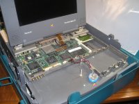
I used to carry a 1GB ZFP HDD back and forth to do work at home in this box. Buying BabyPB, my remaindered PowerBook 100 put an end to that. This rig used to have a PB100 bottom plate bolted up to the bottom side as well. The chassis started out in life as a standard DuoDock. Now, mired in my surreal life, it's sporting . . . well . . . pretty much just its wares with no covering for the Dock/Multifunction PDS card, giving easy access to the power leg jumper hack that turns Dock functions off (but not NuBus, heh! [}] ]'> ) while turning the LCD on at the same time and vice-versa..
This thing has seen some pretty cool setup testing over the years. You just gotta love having the LCD and a great NuBus VidCard's output on a 21" CRT up at the same time. [] ]'>
__________________________________________________
Meanwhile, back at the banana ranch!
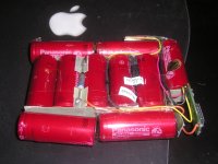
I managed to bust open my copy of BTI's MC-Duo2300 batpack. I has the catch integrated into the slide so that was it for this one, but I was also curious to see what was inside because it looked so much like a standard Apple Config and it turned out to be just that . . . up to a point.
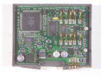
See that same little microprocessor board! This time there is some info on the cells as well, though no hits have turned up as yet:
Panasonic Ni-MH ht15 gc23
Whatever, I can't possibly imagine that Battery Technology Inc, folks in tht business since 1992 as their main line of work, did't know one whole hell of a lot more about building battery packs than anyone at Apple. Not to mention who the notorious cost/corner cutters at Apple from the Duo era would possibly have considered hiring, or actually paying what it cost to produce a well designed battery with a bit of intelligence. The Duo's wall wart appears to pretty much be the village idiot, so a smart battery HAS to help some, or so I would surmise.
Early 5300, battery anyone?
I used to carry a 1GB ZFP HDD back and forth to do work at home in this box. Buying BabyPB, my remaindered PowerBook 100 put an end to that. This rig used to have a PB100 bottom plate bolted up to the bottom side as well. The chassis started out in life as a standard DuoDock. Now, mired in my surreal life, it's sporting . . . well . . . pretty much just its wares with no covering for the Dock/Multifunction PDS card, giving easy access to the power leg jumper hack that turns Dock functions off (but not NuBus, heh! [}
] ]'> ) while turning the LCD on at the same time and vice-versa..This thing has seen some pretty cool setup testing over the years. You just gotta love having the LCD and a great NuBus VidCard's output on a 21" CRT up at the same time. [
] ]'>__________________________________________________
Meanwhile, back at the banana ranch!
I managed to bust open my copy of BTI's MC-Duo2300 batpack. I has the catch integrated into the slide so that was it for this one, but I was also curious to see what was inside because it looked so much like a standard Apple Config and it turned out to be just that . . . up to a point.
See that same little microprocessor board! This time there is some info on the cells as well, though no hits have turned up as yet:
Panasonic Ni-MH ht15 gc23
Whatever, I can't possibly imagine that Battery Technology Inc, folks in tht business since 1992 as their main line of work, did't know one whole hell of a lot more about building battery packs than anyone at Apple. Not to mention who the notorious cost/corner cutters at Apple from the Duo era would possibly have considered hiring, or actually paying what it cost to produce a well designed battery with a bit of intelligence. The Duo's wall wart appears to pretty much be the village idiot, so a smart battery HAS to help some, or so I would surmise.
Early 5300, battery anyone?
I followed up on that notion of "Wall Wart as village idiot" in my caffeine starved line of reasoning and it finally dawned on me! We can isolate the Duo's Battery Charging Circuitry, like so:
How about some educated guesses on how this black magical crap works? This might be helpful in divining just what the hell those mystical doodads actually do inside the battery pack and why a minimal bit of intelligence added on the battery pack end of things might prove to be helpful?
Lemme know. Curiosity about this battery charging voodoo is killing me! [] ]'>
< . . . dragging his knuckles, returns to his cave to resume the lowly task of breaking stuff. [}] ]'> >
How about some educated guesses on how this black magical crap works? This might be helpful in divining just what the hell those mystical doodads actually do inside the battery pack and why a minimal bit of intelligence added on the battery pack end of things might prove to be helpful?
Lemme know. Curiosity about this battery charging voodoo is killing me! [
] ]'>< . . . dragging his knuckles, returns to his cave to resume the lowly task of breaking stuff. [}
] ]'> >
My guess is the chip just tells the Mac what kind of battery it is, with some sort of ID code. Then software on the Mac uses that ID code to decide what charging rate to use for the battery, and maybe also some parameters about what the 100% charged voltage is expected to be. We know that older Duos required a software patch in order to use Type III batteries, so apparently not everything is handled by the battery itself or that wouldn't have been necessary. There are enough rebuild examples online where people just substituted whatever similar cells they had on hand, that I don't think it needs to be an exact match for the original cells.
AHA! :O No, I didn't know that about the patch for the Type III batteries and everything falls into place for me now! :approve:
I already well understood, and agree with, your point about employing similar cells, but the extra magical crap in my toys suggest something more complex going on, IMO.
Given:
1) the first generations of Duo's can't handle Type III without a software patch to the power manager.
2) successful rebuilds are reported for batteries utilizing cells similar to the original pack's specifications.
3) successful rebuilds of batteries utilizing higher capacity cells are known to fail to live up to expectations based upon that extra capacity.
4) I have two types of second source batteries of higher capacity than standard Apple batteries that "just happen to have" some intelligence built into the battery.
Therefore: 1 + 2 + 3 + 4 = The PIC boards in the Higher Capacity Batteries from BTI are the patch! 8-o
Alternately, they lie to the Power Manager as a substitute for the non-existent patch required for the Duo (or charger) to fully charge the higher capacity cells in BTI's premium line of Second Source battery packs.
Selling cheaper knock-offs of standard Apple batteries would be one market, but if an Apple customer had shelled out several grand for the coolest SubNotebook SYSTEM ever devised, they likely wouldn't be interested in using what might be an inferior product in their technojoy. That Apple customer would be a much more likely to shell out additional bread for the added of run time BTI made available at the high end of the performance envelope, a much more lucrative market niche, BTW.
No, I never said it was necessary to reverse engineer this intelligent battery voodoo, I said it might be the answer to all of our Ni-MH battery pack rebuilding woes. It would solve all the cell matching questions as I first said and now I'm convinced that it affords a mechanism for unleashing the much higher energy density of modern cells in our stone age TechnoToys. [] ]'>
I already well understood, and agree with, your point about employing similar cells, but the extra magical crap in my toys suggest something more complex going on, IMO.
Given:
1) the first generations of Duo's can't handle Type III without a software patch to the power manager.
2) successful rebuilds are reported for batteries utilizing cells similar to the original pack's specifications.
3) successful rebuilds of batteries utilizing higher capacity cells are known to fail to live up to expectations based upon that extra capacity.
4) I have two types of second source batteries of higher capacity than standard Apple batteries that "just happen to have" some intelligence built into the battery.
Therefore: 1 + 2 + 3 + 4 = The PIC boards in the Higher Capacity Batteries from BTI are the patch! 8-o
Alternately, they lie to the Power Manager as a substitute for the non-existent patch required for the Duo (or charger) to fully charge the higher capacity cells in BTI's premium line of Second Source battery packs.
Selling cheaper knock-offs of standard Apple batteries would be one market, but if an Apple customer had shelled out several grand for the coolest SubNotebook SYSTEM ever devised, they likely wouldn't be interested in using what might be an inferior product in their technojoy. That Apple customer would be a much more likely to shell out additional bread for the added of run time BTI made available at the high end of the performance envelope, a much more lucrative market niche, BTW.
No, I never said it was necessary to reverse engineer this intelligent battery voodoo, I said it might be the answer to all of our Ni-MH battery pack rebuilding woes. It would solve all the cell matching questions as I first said and now I'm convinced that it affords a mechanism for unleashing the much higher energy density of modern cells in our stone age TechnoToys. [
] ]'>
My working assumption is that the PIC board's function can't merely be informing the Power Manager a Battery Type, capacity or the charging characteristics of a Battery Pack setup outside those defined in Apple Specifications. How it works is Magic, defined as technology beyond the ken of the average person.
I came up empty in my hope of finding the power ratings of these BTI packs in the First Quarter 1995 Macintosh Product Registry. I did find some interesting tidbits, however.
MC-100 - Replacement Battery for the PowerBook 100 (I guess it wasn't possible to improve upon SLA cells for the PB100 )
MC-2410 - BTI Mini AC Adapter (Duo, with listing of MC-0732 for PowerBooks)
MC-170 - High-capacity replacement Battery for PowerBook
Some other aux. battery and Charging products, mostly unrelated.
Which leaves me with just the info printed on my two BTI Battery examples for the time being, I'm going do drag out the file folder box of old magazines and tear-sheets from the period, hoping to find mAh rating for my battery packs or a percentage comparison from which to approximate the capacity of the marked, but especially the unmarked cells in my two examples.
MC-Duo2300 - Obviously a Type III replacement pack, no mention of High-Capacity (Panasonic cells w/two lines of info + date coding)
MC-T4 - I missed the inference of Type IV in the Model no. until now, but with the high-mag reading glasses the designation is unmistakable. The logo's fancy extended crossbar numeral 4 logo has abutting column left copy reading:
HIGH
CAPACITY
TYPE
_______________ <- extended crossbar of numeral four
NiMH
OOPSIE! I remembered it was a high capacity battery from back in the day, also, it sticks out the front of the Duo, being deep enough for a 2 x 5 array of 4/5 A cells, definitely to be avoided if not offering some overriding quality. The extra space left and right is taken up by those cute lil' plastic posicle shims with plenty of room remaining down the centerline for the PIC board.
I'm hoping to rebuild these tow packs with similar/same capacity cells. If someone takes up the challenge of reverse engineering the PIC board's function, it ought to be easy enough to clone it as outlined above. The 2 x 5 AA Cell arrangement in the FrankenPack has beaucoups cubic available for a longer PIC PCB.
I came up empty in my hope of finding the power ratings of these BTI packs in the First Quarter 1995 Macintosh Product Registry. I did find some interesting tidbits, however.
MC-100 - Replacement Battery for the PowerBook 100 (I guess it wasn't possible to improve upon SLA cells for the PB100 )
MC-2410 - BTI Mini AC Adapter (Duo, with listing of MC-0732 for PowerBooks)
MC-170 - High-capacity replacement Battery for PowerBook
Some other aux. battery and Charging products, mostly unrelated.
Which leaves me with just the info printed on my two BTI Battery examples for the time being, I'm going do drag out the file folder box of old magazines and tear-sheets from the period, hoping to find mAh rating for my battery packs or a percentage comparison from which to approximate the capacity of the marked, but especially the unmarked cells in my two examples.
MC-Duo2300 - Obviously a Type III replacement pack, no mention of High-Capacity (Panasonic cells w/two lines of info + date coding)
MC-T4 - I missed the inference of Type IV in the Model no. until now, but with the high-mag reading glasses the designation is unmistakable. The logo's fancy extended crossbar numeral 4 logo has abutting column left copy reading:
HIGH
CAPACITY
TYPE
_______________ <- extended crossbar of numeral four
NiMH
OOPSIE! I remembered it was a high capacity battery from back in the day, also, it sticks out the front of the Duo, being deep enough for a 2 x 5 array of 4/5 A cells, definitely to be avoided if not offering some overriding quality. The extra space left and right is taken up by those cute lil' plastic posicle shims with plenty of room remaining down the centerline for the PIC board.
I'm hoping to rebuild these tow packs with similar/same capacity cells. If someone takes up the challenge of reverse engineering the PIC board's function, it ought to be easy enough to clone it as outlined above. The 2 x 5 AA Cell arrangement in the FrankenPack has beaucoups cubic available for a longer PIC PCB.
Interesting update: my mention of the date coding on the batteries and a second cup of coffee shook loose another tidbit. The MC-T4 must not have been a runaway success due to its unsightly protrusion, the Type 4 designation may have failed to aid in distinguishing this product, posibly even hurting marketing eforts. So BTI appears to have re-thought its marketing scheme and the engineering of its packaging design.
Battery Cell Date Coding:
MC-T4 - cells dated 11/97
MC-Duo2300 - cells dated 8/98
BTI combined the External Slide Catch Integration of the Type I battery with a modification to the Type II/III fat-bar-H configuration, making cubic available for installation of the MC-T4 PIC board. The cell in line with the (now excised) spring button catch mechanism was moved off center (compared to Apple's symmetrical cell arrangement) to the back of the pack. Thus, the increased cubic available in front of that cell became adequate for installation the PIC board from the extended MC-T4!
If I'm reading these tea leaves correctly, a cloned or better yet, updated, flexibly modified PIC board could allow for in-Duo charging of the highest capacity NiMH cells available today. One wonders what kind of run times might be achieved?
Any takers on reverse engineering the crusty MC-T4 battery pack's contents? Standalone Charger/PCB available for this project as well!
< puts more mileage on his knuckles heading back to the coffee pot. >
Battery Cell Date Coding:
MC-T4 - cells dated 11/97
MC-Duo2300 - cells dated 8/98
BTI combined the External Slide Catch Integration of the Type I battery with a modification to the Type II/III fat-bar-H configuration, making cubic available for installation of the MC-T4 PIC board. The cell in line with the (now excised) spring button catch mechanism was moved off center (compared to Apple's symmetrical cell arrangement) to the back of the pack. Thus, the increased cubic available in front of that cell became adequate for installation the PIC board from the extended MC-T4!
If I'm reading these tea leaves correctly, a cloned or better yet, updated, flexibly modified PIC board could allow for in-Duo charging of the highest capacity NiMH cells available today. One wonders what kind of run times might be achieved?
Any takers on reverse engineering the crusty MC-T4 battery pack's contents? Standalone Charger/PCB available for this project as well!
< puts more mileage on his knuckles heading back to the coffee pot. >
You could try putting new NiMH cells in there with the existing PIC, and see what kind of battery performance results. If it's not good enough, then you can worry about how to clone/modify the PIC at that point.
That's actually my plan exactly for the MC-Duo2300 unit! :approve:
Alternately, I'm going to be looking for info in the old magazines or clues to the actual specs of these batteries. I'll likely be calling BTI to ask for help with the recelling project in terms of the original cell specifications for both batteries as well . . .
. . . they've got an honest to goodness Help Desk type Tech Support Phone Number listed! :O
I'm just very curious to see how this stuff works and why it's necessary. I'm offering to send the crufty pack and the charger out if anyone wants to jump start the investigation out of the same kind of curiosity.
Inquiring minds want to know! :lol:
Alternately, I'm going to be looking for info in the old magazines or clues to the actual specs of these batteries. I'll likely be calling BTI to ask for help with the recelling project in terms of the original cell specifications for both batteries as well . . .
. . . they've got an honest to goodness Help Desk type Tech Support Phone Number listed! :O
I'm just very curious to see how this stuff works and why it's necessary. I'm offering to send the crufty pack and the charger out if anyone wants to jump start the investigation out of the same kind of curiosity.
Inquiring minds want to know! :lol:
That probably redirects to a call center office complex in india. LOL You can usually tell when you call in, and it starts to "ring" you can hear other voices cross-talking on the line. Thats happened to me a couple times with paypal, thats how I knew it was being transferred overseas.
I never had a chance to call today, too many fires to put out, but I got a lot done on several fronts, IRL and here as well. :approve:
It's now a little after 4AM and I've pried the cells of the BTI MC-Duo2300 battery just far enough apart to do a circuit diagram. It's late because I couldn't let it go, I also translated the asymmetrical FatBarH into the very neat little 2x5 array of cells. Amazingly enough, all the solder connections for the components happen at the outside ends, leaving a clean center line for the five springs mounted between the pairs of cells.
I stopped by the Shack and picked up three more battery packs to cannibalize, but I'll only need two in addition to the one in the pictures. Since the two intervening components of the circuit are wired up to the separate termination ends from the packs and I need two separate termination ends to attach the battery to the contacts, I only need two of the very cool joint plates.
For now I'm treating the PIC board as a black box, only showing the four wires connected to the three pads on the bottom. After I get the two diagrams done in Illustrator, I'll probably have a go at doing a detail box for the PCB that shows all the traces and the components they connect. Maybe you sorcerers can divine the meaning of this friggin' mess from the diagrams and PCB layout . . .
. . . |) zzzzzzzzzzzzzzzzzzzzzzzzzzzzzzzzzzzz
It's now a little after 4AM and I've pried the cells of the BTI MC-Duo2300 battery just far enough apart to do a circuit diagram. It's late because I couldn't let it go, I also translated the asymmetrical FatBarH into the very neat little 2x5 array of cells. Amazingly enough, all the solder connections for the components happen at the outside ends, leaving a clean center line for the five springs mounted between the pairs of cells.
I stopped by the Shack and picked up three more battery packs to cannibalize, but I'll only need two in addition to the one in the pictures. Since the two intervening components of the circuit are wired up to the separate termination ends from the packs and I need two separate termination ends to attach the battery to the contacts, I only need two of the very cool joint plates.
For now I'm treating the PIC board as a black box, only showing the four wires connected to the three pads on the bottom. After I get the two diagrams done in Illustrator, I'll probably have a go at doing a detail box for the PCB that shows all the traces and the components they connect. Maybe you sorcerers can divine the meaning of this friggin' mess from the diagrams and PCB layout . . .
. . . |) zzzzzzzzzzzzzzzzzzzzzzzzzzzzzzzzzzzz
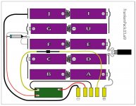
Any weird squiggly lines just show excess wire so I can flop the components back inside the case between the cells.
Anybody know sources of good diagrams of the Types I-III Apple battery packs? Now that the library of parts is built in Illustrator, variations on this theme will be a cinch. I'm going to do my other BTI Battery layout as well as the stock layout of the BTI MC-Duo2300.
The only difference between the two layouts is that the component connected to the yellow wires is in between Cells D & F in the FrankenPack, the real deal has it nestled betwixt cells E & F.
Now what the heck can that PIC board be reading and doing about it?
edit: the thin red(?) wire hooked up between the rocket ship with the blue band and the PCB would be the orange wire in my pics of the unit, :-/
edit again: |) time for bed, it seems I've typo'd the label on cell "H" as well. :
Very nice diagram! The component connected to the yellow wires should be the thermistor. The other two are both fuses, I'm pretty sure. Maybe one is fast blow and one is slow blow.
That looks identical to how my Type I battery is configured, with two exceptions:
- it has the "transistor-looking" ID chip instead of the little green circuit board
- there's no connection between the fuse and the ID chip (the left-most red wire in your diagram)
My Type III battery is configured the same as well, with these exceptions:
- the cells are physically laid out in an H pattern, instead of 5 rows of two cells (but the electrical connections are the same)
- instead of the fuse that looks like a bullet, it has a something that looks like 1 cm square piece of paper with a tiny something inside it
That looks identical to how my Type I battery is configured, with two exceptions:
- it has the "transistor-looking" ID chip instead of the little green circuit board
- there's no connection between the fuse and the ID chip (the left-most red wire in your diagram)
My Type III battery is configured the same as well, with these exceptions:
- the cells are physically laid out in an H pattern, instead of 5 rows of two cells (but the electrical connections are the same)
- instead of the fuse that looks like a bullet, it has a something that looks like 1 cm square piece of paper with a tiny something inside it
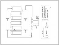
Thanks, big! [] ]'> Now that I've ripped this graphic out of that great howto.pdf I'll be doing all the variations available. I'm hoping it'll be easy enough to see what values for whatever it is that the PIC is shuffling around in there. Knowing what feed what disinformation output is required to hoodwink the the Power Manager into charging whatever capacity cells as BTI did could make it easy for to use any cells we decide now or to use in the future. [}] ]'>
 Hopefully I can get this printed at work to markup and then doink it into Illustrator this evening. :approve:
If anyone can post the real identities of the components of the standard battery as labeled in this diagram, that would help me a lot in doing the rest of the diagrams and in updating this one.
] ]'> Now that I've ripped this graphic out of that great howto.pdf I'll be doing all the variations available. I'm hoping it'll be easy enough to see what values for whatever it is that the PIC is shuffling around in there. Knowing what feed what disinformation output is required to hoodwink the the Power Manager into charging whatever capacity cells as BTI did could make it easy for to use any cells we decide now or to use in the future. [}] ]'>Hopefully I can get this printed at work to markup and then doink it into Illustrator this evening. :approve: If anyone can post the real identities of the components of the standard battery as labeled in this diagram, that would help me a lot in doing the rest of the diagrams and in updating this one.
This diagram seemed totally different from the two Duo Batteries that I have opened up, I thought maybe mine were a different type at first. I think I was just tired. Now it looks to me like he's showing the center pair of components flipped out tho the outside of the pack as I did in my first diagram. The Batteries aren't set up with the terminal matching the pattern in my packs, Maybe he thought it was a clearer presentation?
Dunno, I'm much more tired than I was when I started . . .
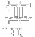
. . . but playing in Illustrator and GraphicConverter are very soothing activities for me. [] ]'>
This is the pre-FrankenPack AA Hack, stock config of my later model, standard size, high capacity BTI Duo Battery.
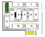
The main difference that jumps out at me is the four count of discrete components in the Apple Bat, are reduced to only three in the BTI Bat, with that PIC card as an intelligent substitute? Dunno . . . over my head . . . I'll just keep doin' my thing: making pretty pictures and breaking things.
I'll be doing the Apple Bat and the other (oversized) BTI Bat diagrams before I start cutting things apart. [}] ]'>
Dunno, I'm much more tired than I was when I started . . .
. . . but playing in Illustrator and GraphicConverter are very soothing activities for me. [
] ]'>This is the pre-FrankenPack AA Hack, stock config of my later model, standard size, high capacity BTI Duo Battery.
The main difference that jumps out at me is the four count of discrete components in the Apple Bat, are reduced to only three in the BTI Bat, with that PIC card as an intelligent substitute? Dunno . . . over my head . . . I'll just keep doin' my thing: making pretty pictures and breaking things.
I'll be doing the Apple Bat and the other (oversized) BTI Bat diagrams before I start cutting things apart. [}
] ]'>I count four components in both batteries: two fuses, a thermistor, and either a PIC or an ID thingy that looks like a transistor.
The little blue thingie must be part of the PCB in the BTI Pack, it's not present otherwise. The "Paper thing that looks like it has something in it" or some such appears to me to be the Tab -> Flex Circuit connection.
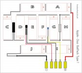
I was counting the PIC PCB as an anomaly, not as an active component per se, it's just a tad more complex than the ApplePack's little blue thingie. [ )] ]'>
After I print out the Apple BatPack Diagram, I'm going to try to deduce the logical function of the anomalous "Black Box" from the differences in components and I/O at the contacts between brands.
I was counting the PIC PCB as an anomaly, not as an active component per se, it's just a tad more complex than the ApplePack's little blue thingie. [
)] ]'>After I print out the Apple BatPack Diagram, I'm going to try to deduce the logical function of the anomalous "Black Box" from the differences in components and I/O at the contacts between brands.
Here's the grayed out version of my Apple Bat (Type?) with the markup of the differences from the BTI pack.
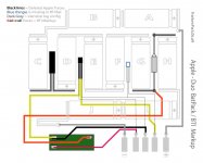
It looks to me like no signal comes from, or goes back to, the Power Manager on those three contacts without going through the BTI PIC Card were that unique orange input line comes into play somehow.
Methinks the PIC on this PCB is a congenital liar. [}] ]'>

edit: I should have noted that the THIN black lines are the deleted/contrasting traces for comparison purposes.
The heavy gray lines are the RED WIRE and thick flex cable power transmission lines.
It looks to me like no signal comes from, or goes back to, the Power Manager on those three contacts without going through the BTI PIC Card were that unique orange input line comes into play somehow.
Methinks the PIC on this PCB is a congenital liar. [}
] ]'>edit: I should have noted that the THIN black lines are the deleted/contrasting traces for comparison purposes.
The heavy gray lines are the RED WIRE and thick flex cable power transmission lines.
Phase 1 complete: FrankenPack™
Now the real work begins! [] ]'>
Synopsis of the gobbledegook posted above:
After having documenting the 4/5 A Cell MC-Duo2300, I've disassembled its innards and fitted them into the empty shell along with the stand-in standard AA cells.

The documentation the new FrankenPack™ cell/circuitryconfiguration for the off the shelf AA NiMH Cells above as well:

The documentation for utilizing cannibalized parts from three CrapShack 2 x AA Battery Packs ( approx. $2 ea.) is on the previous page.

I'll be contacting BTI regarding the proper capadity cells for the two versions of their High Capacity Batteries. But for now I'll just go ahead and buy another pair of four packs of the 2450mAh Energizers to match the most recently purchased rechargeables I have on hand just to see what kind of run times I can get with those! [}] ]'>
I still need to Diagram the BTI MC-T4, but there's no rush on that, its circuitry is very likely identical to the MC-Duo2300.
Now the real work begins! [
] ]'>Synopsis of the gobbledegook posted above:
After having documenting the 4/5 A Cell MC-Duo2300, I've disassembled its innards and fitted them into the empty shell along with the stand-in standard AA cells.
The documentation the new FrankenPack™ cell/circuitryconfiguration for the off the shelf AA NiMH Cells above as well:
The documentation for utilizing cannibalized parts from three CrapShack 2 x AA Battery Packs ( approx. $2 ea.) is on the previous page.
I'll be contacting BTI regarding the proper capadity cells for the two versions of their High Capacity Batteries. But for now I'll just go ahead and buy another pair of four packs of the 2450mAh Energizers to match the most recently purchased rechargeables I have on hand just to see what kind of run times I can get with those! [}
] ]'>I still need to Diagram the BTI MC-T4, but there's no rush on that, its circuitry is very likely identical to the MC-Duo2300.
Cool, I'm looking forward to your results.
THX, me too! What do you make of that BTI markup diagram I did over the Apple Battery circuit diagram? Is it clear enough? Suggestions?
I've got a very nearly destroyed Apple battery that I think I'll turn into a makeshift breadboard so I can hook up a prototype using whatever standard battery holders I can scavenge around here. Might as well make sure that devious lil' PICamajigger is still in working order. Doing a dry run of everything without waiting for the serious hackage to be completed seems the thing to do.
First: Is my previous post a clear enough explanation of the silliness it's taken to get to this point? I can edit in changes, more pics a/o verbiage as needed to make it sound like "English."
Second: I think I've finally figured out a way to make reassembly/breakdown a snap. [] ]'>
I've got a very nearly destroyed Apple battery that I think I'll turn into a makeshift breadboard so I can hook up a prototype using whatever standard battery holders I can scavenge around here. Might as well make sure that devious lil' PICamajigger is still in working order. Doing a dry run of everything without waiting for the serious hackage to be completed seems the thing to do.
First: Is my previous post a clear enough explanation of the silliness it's taken to get to this point? I can edit in changes, more pics a/o verbiage as needed to make it sound like "English."
Second: I think I've finally figured out a way to make reassembly/breakdown a snap. [
] ]'>