

Thread
PowerBook Duo battery replacement
Now that I've got a Visible/MinimalistDuo™ RevII for torturing with alligator clips I've got a question for you. Are the wires on the CrapShack holders really heavy enough to do the job? The new four-packers have much thinner gauge wires than my older packs and the wires on those are more lightweight than the Tabs and especially the Red Wire in the ApplePacks.
Wire gauge advice for when I start hanging batteries on the lid? :?:
Wire gauge advice for when I start hanging batteries on the lid? :?:
See http://www.powerstream.com/Wire_Size.htm
I would guesstimate the Duo pulls about 1 amp or less from the battery. So you'd want something like 28 AWG wire, or heavier.
I would guesstimate the Duo pulls about 1 amp or less from the battery. So you'd want something like 28 AWG wire, or heavier.
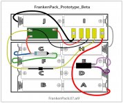
Hey, big, if you get a chance, could you (or anyone else for that matter) compare the FrankenBat™ diagram to the Beta Prototype for error checking? I'd appreciate it, My vision is blurry and I need to get some sleep.
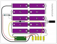
OK, then, I've got wire, I picked up another double holder and found a pair of Quad AA Holders. I'm using a pair of each cut down to as close an approximation as I can get to the final packaging of the FrankenPack™ design. Doing it this way puts all three components in the 4/8 Cell section where they belong, one column in the 2/4 casing yields the other two Cells and free cubic to house the PIC Board and the five contact terminals (shown as battery contacts) for the wolligator-wire-up to the new Duo TestBed's prongs.
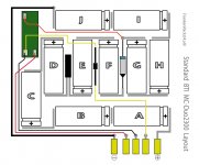
Might as well put the original layout I did of the MC-Duo2300 before i took it apart. Can anyone spot any circuit errors in comparing between the three?
:?:
OK, then, I've got wire, I picked up another double holder and found a pair of Quad AA Holders. I'm using a pair of each cut down to as close an approximation as I can get to the final packaging of the FrankenPack™ design. Doing it this way puts all three components in the 4/8 Cell section where they belong, one column in the 2/4 casing yields the other two Cells and free cubic to house the PIC Board and the five contact terminals (shown as battery contacts) for the wolligator-wire-up to the new Duo TestBed's prongs.
Might as well put the original layout I did of the MC-Duo2300 before i took it apart. Can anyone spot any circuit errors in comparing between the three?
:?:
I think it's time to stop make Illustrator diagrams, and just put some cells in your homebrew battery and try it out! 
The green board is wired differently in your third diagram. That green board has three pads on it in an L shape. If the top of the L is pad 1, the corner is pad 2, and the foot of the L is pad 3, then your diagrams work out this way:
Diagrams 1 and 2
pad 1: battery terminal 2
pad 2: battery terminal 3
pad 3: voltage from four cells (about 5V)
Diagram 3
pad 1: voltage from four cells (about 5V)
pad 2: battery terminal 3
pad 3: battery terminal 2
The green board is wired differently in your third diagram. That green board has three pads on it in an L shape. If the top of the L is pad 1, the corner is pad 2, and the foot of the L is pad 3, then your diagrams work out this way:
Diagrams 1 and 2
pad 1: battery terminal 2
pad 2: battery terminal 3
pad 3: voltage from four cells (about 5V)
Diagram 3
pad 1: voltage from four cells (about 5V)
pad 2: battery terminal 3
pad 3: battery terminal 2
:lol: Maybe so, but I'm NOT an electronics guy by any stretch of the imagination. I'm a visual thinker/hardware hacker only, so doing an electron plumbing diagram in Illustrator is a necessary tool for me, not a reason for procrastination. Having you back-stop me on the wiring setup is a big help. I have several Duos, several standard Apple batteries and therefore several chances to get that right.
Conversely, I have only one (probably good ) PIC board from which to vent the dreaded MAGIC SMOKE!!!!!!!!!!!!!! :O
Such being the case, I'm currently assembling the external battery pack built into the Minimalist Duo Mk.II case in order to test the acid etched backup PIC board first!
I'm trying to be methodical and to clearly diagram every known Duo battery configuration. I need a pic of the innards of a complete Type I battery from someone, BTW.
Is the latch mechanism arrangement the only way to easily tell the Types apart?
_____I have:
_____________spring loaded short button Model Number: M1499
_____________long button, slide integrated latch Model Number: M7782
Are there any additional configurations besides the AA Cell Type I Battery?
. . . and now to pore over the diagrams for the error you noted, I can't easily process your .TXT :I
Conversely, I have only one (probably good ) PIC board from which to vent the dreaded MAGIC SMOKE!!!!!!!!!!!!!! :O
Such being the case, I'm currently assembling the external battery pack built into the Minimalist Duo Mk.II case in order to test the acid etched backup PIC board first!
I'm trying to be methodical and to clearly diagram every known Duo battery configuration. I need a pic of the innards of a complete Type I battery from someone, BTW.
Is the latch mechanism arrangement the only way to easily tell the Types apart?
_____I have:
_____________spring loaded short button Model Number: M1499
_____________long button, slide integrated latch Model Number: M7782
Are there any additional configurations besides the AA Cell Type I Battery?
. . . and now to pore over the diagrams for the error you noted, I can't easily process your .TXT :I
I could have sworn I'd already posted this:
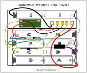

That now looks the same as the 3rd of the three diagrams from your previous post. But I've lost track of what all these diagrams represent.
The third (bottom of the three) diagram is a graphical representation of BTI MC-Duo2300 configuration as pictured below the revised diagram.
The larger, original Pic of the MC-Duo2300 is on the previous page.
I've bought enough holders to build two external battery packs into the lid of the new minimalist Duo testbed. The first one will use standard Apple Components with AAs in the same configuration as the revised FrankenPack™ Beta Prototype diagram.
As a matter of fact, I'm hoping to be run time testing the standard Apple charging circuitry against the, PIC Board enhanced, BTI high capacity recharging hack doing, using exactly the same 10 AA Cells in each ProtoPack for the tests. [}] ]'>
Yesterday I spent wrasslin' to get the LCD out of the badly borken-n-crumbling Duo Lid. Right now it is just mounted the front bezel and hinge assy. with no back/top. I need to epoxy a new brass bolt insert in to repair the top of the original busted up lid.
It was fun! ;D
The larger, original Pic of the MC-Duo2300 is on the previous page.
I've bought enough holders to build two external battery packs into the lid of the new minimalist Duo testbed. The first one will use standard Apple Components with AAs in the same configuration as the revised FrankenPack™ Beta Prototype diagram.
As a matter of fact, I'm hoping to be run time testing the standard Apple charging circuitry against the, PIC Board enhanced, BTI high capacity recharging hack doing, using exactly the same 10 AA Cells in each ProtoPack for the tests. [}
] ]'>Yesterday I spent wrasslin' to get the LCD out of the badly borken-n-crumbling Duo Lid. Right now it is just mounted the front bezel and hinge assy. with no back/top. I need to epoxy a new brass bolt insert in to repair the top of the original busted up lid.
It was fun! ;D
Maybe the progression of diagrams is way confusing. They're all labeled for identity and filename. I've been working toward making a final post with the diagrams of all three Duo Bats from Apple and my two BTI Bats all together. The ProtoPacks won't be in there to avoid confusion. I hope such a post will enable future hackers to proceed more easily in their projects. Schematic of what's happening electrically would be much appreciated, I can knock those out in AI as well, that's fun! [That now looks the same as the 3rd of the three diagrams from your previous post. But I've lost track of what all these diagrams represent.
 ] ]'>
] ]'>Could you please do a rough sketch of what your Type I battery circuitry was before you moved everything around and give me the model number? :?:
If someone could identify the model Numbers of all three Apple Bats that would be a big help in labeling the diagrams. I think I've previously posted the model numbers for Types II & III, but I'm not sure which is which.
We're getting there, first I'm building the Apple Duo Type X ProtoPack in the lid. The Battery holder assemblies I'm doing simultaneously and testing the Apple pack to make sure that works before trying vent the Magic Smoke from either of my two PIC Boards in the revised BTI Beta ProtoPack. [
] ]'>I'm planning on using screw down barrier strips for strain relief of the cable, that shouldn't pose any electrical problems should it?
I'm planning on using some ATX power extension Cables for the hookup. I'll be soldering the power lines to the vertical internal tabs of the MoBo contacts.
I'll be adding three contacts for ADB, along with just enough to break serial and EtherNet of the Duo TestBed's hull for future hacks. plug will hang from the left side of the Duo, with socket on each of the external battery packs so I can use an extension cable to hook either pack up to the Duo for power and the rest of the signals will be terminated to a stock Crapshack PCB, probably with header connections and/or hardwired sockets.
Could the extra wiring a/o screw down barrier strip cause any electrical signal or power transmission problems? :?:
I'm not clear what the middle diagram (FrankenPack) is. Am I right, your goal is to build a new battery (first diagram) that's internally identical to the BTI battery (third diagram)?
I'm afraid I can't give a diagram, since I already tore the whole thing apart, but I described it several posts back. Replace your green board with the ID chip that looks like a transistor, eliminate the orange wire, and you've basically got it. The model number of my Type I is M7782 and my Type III is M1499.
I'm not exactly sure what you mean, but as long as you're not creating a short circuit on bare metal somewhere, just having some extra metal inside shouldn't cause any problems. It's a battery and power cable, not a radio.
Very good, it's full speed ahead in that case. THX, big.