

Thread
DIY Localtalk - Ethernet converter
I have a EtherPrint ethernet-to-localtalk bridge that seems to work well enough to netboot my IIGS from and connect to a netatalk share I have locally. I'm not sure what the traditional baud rate of the serial side is -- I assume 230K -- but I'm pretty sure I could emulate this functionality in a couple of arduinos. So I've been taking data snapshots of Appletalk packets coming from various equipment on the localtalk side (from the bridge) and packets from the ethernet side to the bridge. The format seems to be straight-forward. The packet captures were taken with Wireshark. Once I figure out how to convert the Localtalk serial RS-422 to RS-232, then I might be able to listen to communication on the serial side. I'm sure Basilisk II and other OSS emulators will help out in this regard too.
Anybody interested in something like this? The nice part about a solution liek this is that it's totally modular -- there's nothing to say a beaglebone or embedded ARM machine with GPIO pins couldn't handle and supplant this solution with additional things like a netatalk Appleshare system or other things....
Anybody interested in something like this? The nice part about a solution liek this is that it's totally modular -- there's nothing to say a beaglebone or embedded ARM machine with GPIO pins couldn't handle and supplant this solution with additional things like a netatalk Appleshare system or other things....
I'm definitely going to be keeping an eye on this thread.
The wirehark logs make the bitstream look a little cryptic, but it certainly follows *a* pattern that I can see. I just need to do more research on what each "message" across the ethernet wire looks like, document those, and then move onto the serial side to see what the serial side looks like. If they match, i'm a winner and this will be probably be really easy.
I'll do some tests this weekend now that appletalk/netatalk/ethertalk communication is again established in the home base.
I'll do some tests this weekend now that appletalk/netatalk/ethertalk communication is again established in the home base.
So as soon as I came home, I grabbed a OS9 machine and a Leopard machine and my Linux laptop to act as hallway monitor.
Fired up Wireshark --- and......a TON of packets from my wife on the LAN, because she's doing homework. And it's too much to sort through. So I brought out a old dd-wrt router, and rinsed/repeated. This time I was able to capture the *entire* conversation between the OS9 TiBook and the Powerbook G4.
Here's the steps I followed:
-Went to chooser, typed in IP*
-Hit OK, got login prompt. Entered correct password, but invalid username (I could say I meant to do this, but I didn't lol)
-Mounted 'Macintosh HD' after successful login.
-Browsed the HD for a bit
-Dragged Appletalk-mounted HD to trash.
COnfirmed server disconnection, then stopped wireshark capture. The protocol itself is pretty straightforward. What i'm hoping is the pieces i'm seeing on the ethernet side (in ASCII) correspond to what I will eventually see on the serial-only side
SO the next step is to build a device that will listen to the serial bus and spit out what its saying.... then match them up.
*fingers crossed*
Fired up Wireshark --- and......a TON of packets from my wife on the LAN, because she's doing homework. And it's too much to sort through. So I brought out a old dd-wrt router, and rinsed/repeated. This time I was able to capture the *entire* conversation between the OS9 TiBook and the Powerbook G4.
Here's the steps I followed:
-Went to chooser, typed in IP*
-Hit OK, got login prompt. Entered correct password, but invalid username (I could say I meant to do this, but I didn't lol)
-Mounted 'Macintosh HD' after successful login.
-Browsed the HD for a bit
-Dragged Appletalk-mounted HD to trash.
COnfirmed server disconnection, then stopped wireshark capture. The protocol itself is pretty straightforward. What i'm hoping is the pieces i'm seeing on the ethernet side (in ASCII) correspond to what I will eventually see on the serial-only side
SO the next step is to build a device that will listen to the serial bus and spit out what its saying.... then match them up.
*fingers crossed*
 Nice Hack!
Thanks -- It's nice knowing I can give back to the vintage mac community. According to some, I might be able to make RS-422 work like RS-232 which would work nicely in my arduino, but I'm not sure its literally that easy. Anybody else have any ideas on that?
Once I get that part worked out, the fun part will be making the glue that is between the ethernet side and the localtalk side.
And another question is -- should I just go ahead and make this more compatible with the common phonenet boxes and just figure out how *they* work while i'm in there (since I dont actually have a serial cable)...or should I just stick with regular ol' localtalk?
Actually thinking about it, I might incorporate Zigbee into the mix too, because whats even better than having a wireless localtalk network is having a bridged and wireless localtalk network --- then you'd just need a "base station" and just a converter on each machine.
Once I get that part worked out, the fun part will be making the glue that is between the ethernet side and the localtalk side.
And another question is -- should I just go ahead and make this more compatible with the common phonenet boxes and just figure out how *they* work while i'm in there (since I dont actually have a serial cable)...or should I just stick with regular ol' localtalk?
Actually thinking about it, I might incorporate Zigbee into the mix too, because whats even better than having a wireless localtalk network is having a bridged and wireless localtalk network --- then you'd just need a "base station" and just a converter on each machine.
I always thought 232 was a shorter distance subset of 422 and they were pretty much compatible right off the bat.
What kind of serial cable do you need, straight or null-modem (Printer) for DIN8 or D-shell (whatever)-9 pin.
PM me with your needs for a freeb.
Actually post'em here just in case I don't have what you need.
What kind of serial cable do you need, straight or null-modem (Printer) for DIN8 or D-shell (whatever)-9 pin.
PM me with your needs for a freeb.
Actually post'em here just in case I don't have what you need.
Now I believe they're *compatible* but i'm not sure how compatible. Some say apple supported 232 right out of the port for modems, but I'm not totally sure if I do whatever is needed to make it look like a 232 port if i'd get appletalk traffic, and then other sites say it's a differential interface, and you tie certain pins to ground, like TX- and RX- or something. I'm trying to find the link I found at work.
http://pinouts.ru/Converters/rs422_cable_pinout.shtml
Now we're talking.
http://pinouts.ru/Converters/rs422_cable_pinout.shtml
Now we're talking.
I found out that the data is encoded using some modulation to ensure the data is valid and that the Appletalk driver itself (in software) talks directly to the port, not via any other serial method. I was confused to find out that schematics for creating a DIY phonenet box didn't include *anything* with DTR/DCD lines, but that's because the mac is more or less bit-banging the serial port itself rather than relying on the standard spec. I found a book called Inside Appletalk that i'm trying to procure now for more information. If anybody has this book PM me.
http://www.mactech.com/articles/mactech/Vol.02/02.04/ATalkConnections/index.html
http://www.mactech.com/articles/mactech/Vol.02/02.04/ATalkConnections/index.html
I have Inside AppleTalk (the book). No, you can't have it, but I can try to look stuff up in it for you. I thought I had the Inside Macintosh pdf of it, but it looks like I don't.
Eh -- it's on amazon for like $4. So i'll just buy it. I dont even know at this point which questions to ask so i'll just buy it.
I really really really am on top of this project though lol
I really really really am on top of this project though lol
[No message]
Problem with that is instead of a picture you get some garbage text like FULL PG PIC or something....
And the font for some reason is KILLING my eyes --
And the font for some reason is KILLING my eyes --
Come on guys. We don't do piracy here, you know that.
Inside Appletalk in hardback form has been purchased. I suppose at some point i'll need to buy/build a logic analyzer but for now more research is needed.
Any of these any use to you?
http://en.wikipedia.org/wiki/Bus_Pirate
http://en.wikipedia.org/wiki/PLAICE
I may add more as I find them.
/eta/
https://www.sparkfun.com/products/9857 aka http://dangerousprototypes.com/open-logic-sniffer/
http://en.wikipedia.org/wiki/Bus_Pirate
http://en.wikipedia.org/wiki/PLAICE
I may add more as I find them.
/eta/
https://www.sparkfun.com/products/9857 aka http://dangerousprototypes.com/open-logic-sniffer/
The hurdle I'm at now is the physical connection. I'm not sure if I can just wire the port up like RS232 (as on the Mac to internet via serial thread) or If I have to go RS422. I can buy the transceivers online, so thats not a problem, it just isn't fun waiting for parts.
The serial/printer combo port on the Duos worked just fine with PC oriented Modems, if that tells you anything useful. It seems like you probably covered that already . . . but just in case.
RS-422 is a point to point only. just like RS232.
In order to setup a bus network, it has to be converted to RS-485, which is what the phonenet stuff actually does. in sorts...
But you can listen on a direct RS-422 bus if you take the TX/rX lines and mix them. Again, sorta like phonenet does.
In order to setup a bus network, it has to be converted to RS-485, which is what the phonenet stuff actually does. in sorts...
But you can listen on a direct RS-422 bus if you take the TX/rX lines and mix them. Again, sorta like phonenet does.
The phonenet adaptor takes those TX/RX pairs and combines them into a single TX/RX pair. It's rather a simple schematic to look at, yet it works perfectly.
I think I'm going to see if wiring that port up RS232 fashion works -- if it does then I kinda know that this might work out. I'm just looking for a bunch of crap to go over the lines. Then I can actually figure out what all that means. I'm also hoping the INside Appletalk book will help too -- it better for $36
edit: it didnt make sense
I think I'm going to see if wiring that port up RS232 fashion works -- if it does then I kinda know that this might work out. I'm just looking for a bunch of crap to go over the lines. Then I can actually figure out what all that means. I'm also hoping the INside Appletalk book will help too -- it better for $36
edit: it didnt make sense
Well, localtalk is LLAP. Its defined in that standard how it talks on the port.
So all an ethernet adapter is, is an LLAP to Ethernet translator.
So what you need to do is lookup LLAP and find out how it is framed, etc... and use the arduino to decode it. Phone-Net appears to convert the RS422 full duplex bus into a single RS-485 half-duplex bus system.
So all you need is to setup the localtalk bus as half-duplex with only D+ and D- lines. Then hook these into a regular MAX488 or an ADM483 transceiver, to the AVR.
That will establish something that can listen/talk on the bus. BUT you need to come up with a way to decode the databits on the bus, which is all in the LLAP standard.
So all an ethernet adapter is, is an LLAP to Ethernet translator.
So what you need to do is lookup LLAP and find out how it is framed, etc... and use the arduino to decode it. Phone-Net appears to convert the RS422 full duplex bus into a single RS-485 half-duplex bus system.
So all you need is to setup the localtalk bus as half-duplex with only D+ and D- lines. Then hook these into a regular MAX488 or an ADM483 transceiver, to the AVR.
That will establish something that can listen/talk on the bus. BUT you need to come up with a way to decode the databits on the bus, which is all in the LLAP standard.
Here is an LLAP Data frame:
The Flags bytes are 0x7E. Communication follows CSMA/CD
The modulation technique I dont know.
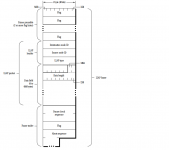
The Flags bytes are 0x7E. Communication follows CSMA/CD
The modulation technique I dont know.
Yeah for that part I've already realized I'll need to buy a MAX488 or similiar.
Yeah decoding the transmissions is something that was an obvious plan item (and a big one at that) but I hadn't gotten there. Gotta get PHY done first, then work backwards.
Yeah decoding the transmissions is something that was an obvious plan item (and a big one at that) but I hadn't gotten there. Gotta get PHY done first, then work backwards.
Wow! That frame chart will help immensely! 
More information:
Localtalk uses 230.4KBps Biphase space encoding (FM0 encoding) over the RS-422/RS-485 differential pair.
Known as SDLC or Synchronous Data Link Control.
Bit timing is 4.34uS. a 1 bit is a full state for each bit period. It will either be high, or low for the entire 4.34uS duration of the bit timing.
A 0 bit produces a high/low transition exactly half-bit timing, or double the frequency of 1.
Bi-Phase Space
Level change occurs at the beginning of every bit period
"One" is represented by no midbit level change
"Zero" is represented by a midbit level change.

This is why LLAP uses Synchronization via the Flag Bytes, 0x7E.
You have to setup a timer in the AVR using 4.34uS data bit timings. Problem is, You dont know when the "start" condition of a byte occurs. So to get around that, they used the flag byte to synchronize when the first bit of a byte occured.
The easiest thing to do is setup the AVR for pin-change interrupt. Use the timer to keep track of the periods between transitions, then you will know when 1 bits and 0 bits occur. Then you will use the 0x7E to keep track of start/stop of databytes.
For example, when the pin-change interrupt occurs, setup the timer at 0. it will count until the next transition. If the timer counted 4.34uS, that was a 1 bit. if it counted 2.17uS, it was a 0 bit. The first 8 bits received are stored. and checked against 0x7E. Of course it wont be correct because your not synchronized. Thats why the Flag Byte is send multiple times. Once you are able to get enough bits received, you can figure out where your start bit is supposed to be. Fix your start position in the code, and boom now your synched. Now of course youll have to correct in code for double transitions otherwise youll end up with false bits and more bits than you need. hehe.
Simple.
Localtalk uses 230.4KBps Biphase space encoding (FM0 encoding) over the RS-422/RS-485 differential pair.
Known as SDLC or Synchronous Data Link Control.
Bit timing is 4.34uS. a 1 bit is a full state for each bit period. It will either be high, or low for the entire 4.34uS duration of the bit timing.
A 0 bit produces a high/low transition exactly half-bit timing, or double the frequency of 1.
Bi-Phase Space
Level change occurs at the beginning of every bit period
"One" is represented by no midbit level change
"Zero" is represented by a midbit level change.
This is why LLAP uses Synchronization via the Flag Bytes, 0x7E.
You have to setup a timer in the AVR using 4.34uS data bit timings. Problem is, You dont know when the "start" condition of a byte occurs. So to get around that, they used the flag byte to synchronize when the first bit of a byte occured.
The easiest thing to do is setup the AVR for pin-change interrupt. Use the timer to keep track of the periods between transitions, then you will know when 1 bits and 0 bits occur. Then you will use the 0x7E to keep track of start/stop of databytes.
For example, when the pin-change interrupt occurs, setup the timer at 0. it will count until the next transition. If the timer counted 4.34uS, that was a 1 bit. if it counted 2.17uS, it was a 0 bit. The first 8 bits received are stored. and checked against 0x7E. Of course it wont be correct because your not synchronized. Thats why the Flag Byte is send multiple times. Once you are able to get enough bits received, you can figure out where your start bit is supposed to be. Fix your start position in the code, and boom now your synched. Now of course youll have to correct in code for double transitions otherwise youll end up with false bits and more bits than you need. hehe.
Simple.
Okay I wonder if I can forget the RS232 stuff because its worthless to me anyway in this project, and just write some code for the arduino to look at data coming in from the PWM pins -- I really could use a logic analyzer but the salae logic is like $199 which is a little out of my range right now (saving for a house down payment this year). I'm going to write something to monitor the D+/D- lines and see what I get. I dont know for sure if I can make a tight enough C++ loop to get down to the 4us range, but it wouldn't hurt trying either.
I dont know what I was thinking trying to wire this up 232 style. Thanks for turning me in the right direction.
I dont know what I was thinking trying to wire this up 232 style. Thanks for turning me in the right direction.
Once you have the entire frame stored in the AVR's RAM, its your discretion what you do with that frame. Send it over RS232 serial, or send it over bluetooth. Or send it over encapsulated UDP/TCP to another end.
Or convert it from LLAP to Ethertalk. Once you get the inside appletalk im sure it has ethertalk in it. But since AVRs are sorta slow, the best thing to do is receive the frame and hold up the bus until you get done processing, so the connected mac dont continue to talk until the bus is free. follow CSMA/CD to do this.
No you cannot use the PWM pins. Thats for output only. There are 2 ways to do this. You can either sample a datapin with a timer set for the proper bit timings but its MUUCH harder to synchronize. Easier to use the 2nd option, which is connect one of the data lines on an interrupt pin. such as INT0, or INT1. As long as you can set it to interrupt on both rising and falling transitions.
You still need the transceiver, as i dont think the data lines are 5V. They are 12V i believe.
This is frequency modulation FM0. or biphase, whatever the engineers call it these days. NOT pulse width modulation.
Or convert it from LLAP to Ethertalk. Once you get the inside appletalk im sure it has ethertalk in it. But since AVRs are sorta slow, the best thing to do is receive the frame and hold up the bus until you get done processing, so the connected mac dont continue to talk until the bus is free. follow CSMA/CD to do this.
No you cannot use the PWM pins. Thats for output only. There are 2 ways to do this. You can either sample a datapin with a timer set for the proper bit timings but its MUUCH harder to synchronize. Easier to use the 2nd option, which is connect one of the data lines on an interrupt pin. such as INT0, or INT1. As long as you can set it to interrupt on both rising and falling transitions.
You still need the transceiver, as i dont think the data lines are 5V. They are 12V i believe.
This is frequency modulation FM0. or biphase, whatever the engineers call it these days. NOT pulse width modulation.
Is there any upper limit to the size of a frame? Because I'm not sure if I have enough ram in my 328P to store a entire frame in RAM?
I'm going to have to do some research on interrupts. This is exactly the kind of project I need to teach myself low-level AVR things, and on the surface it seems easy, but I just need to go ahead and set something up.
Now, another question --- suppose that I wanted to make this go in-line between two phonenet nodes --- the data will be the same, but half duplex, correct?
I'm going to find a S-video cable and destroy it, and go ahead and hook this up to a arduino and start playing with it.
I'm going to have to do some research on interrupts. This is exactly the kind of project I need to teach myself low-level AVR things, and on the surface it seems easy, but I just need to go ahead and set something up.
Now, another question --- suppose that I wanted to make this go in-line between two phonenet nodes --- the data will be the same, but half duplex, correct?
I'm going to find a S-video cable and destroy it, and go ahead and hook this up to a arduino and start playing with it.
Oh okay so I still need a transciever --- I'll still need to buy a MAX488, or do some level shifting somehow. Once I get it to 5V levels, I should be able to view the bits...I'm assuming the MAX488 will be for output back to the bus
maximum frame size is 603 bytes. Ever...
Anyway, You are going to need the transceiver. Also the transceiver has direction control as well. You can listen on the bus, or transmit back to the bus. Or you can turn off the receiver, and transmitter and itll sit totally transparent on the bus.
S-video cables wont work. Thats for the ADB bus. not the serial bus.
Anyway, You are going to need the transceiver. Also the transceiver has direction control as well. You can listen on the bus, or transmit back to the bus. Or you can turn off the receiver, and transmitter and itll sit totally transparent on the bus.
S-video cables wont work. Thats for the ADB bus. not the serial bus.