

Thread
I want to do this...
What HDD? 
100% flat SE bezel with trayloader and Apple II logo medallion would be very
Flattening the curvature of the CRT fillet for an LCD installation without the bubble would be even more so! }
100% flat SE bezel with trayloader and Apple II logo medallion would be very
Flattening the curvature of the CRT fillet for an LCD installation without the bubble would be even more so! }
Getting better all the time. I'm to a point where I think I can proceed by hand sanding and filling.
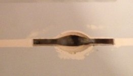
Yer gettin' there, but what's with the closeup teaser . . .
. . . show us what the whole thing looks like ATM. Illustrate your vision coming to life. :approve:
. . . show us what the whole thing looks like ATM. Illustrate your vision coming to life. :approve:
I had to crop the giant iPhone pic to get it to fit the forum.
This is it on a slightly yellower Classic (I) bucket I had handy.
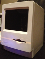
If you squint you can see the idea coming through to reality. Kinda neat!
This is it on a slightly yellower Classic (I) bucket I had handy.
If you squint you can see the idea coming through to reality. Kinda neat!
smoothed out it kind of also looks like a 128/512/plus. awesome.
This is exactly what made me pursue this past a v-hack. It's what Apple should have done in 1994: a real Tenth Anniversary Mac that addressed all of the shortcomings of the compact Macs wrapped in the (brought up to then-current style) original form factor.
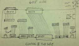
Here's a sketch (pardon my lack of pen skills) of what I'm thinking for the stealth single-layer PCB that'll move the connections of the 605's board to the very different port-holes on the Classic II's tub.
I'd like the connectors on the tub side soldered to the board, with traces over to posts that can be used with pigtail cables to attach to the 605, except the SCSI which will use traces across the board. On the 605 side only the DA15 (video) and SCSI male connectors will be on the board, to provide physical support/positioning, and to get the video signal out of the 605 and to posts for the cable up to the MiniMonoSVGA screen.
Where the Classic II has a D?-19 external FDD port, I'd like to try to shoehorn in a DE-15 (VGA) and an RJ45 (Ethernet), if I can't manage that I'll have to use the D?-19 connector and make a dongle out of an external FDD cable with VGA and Ethernet ends.
The reason I'd like to have a VGA port on the back is: I'd like to be able to switch between the internal 605's video signal and an external source for the screen, so I could run the box as a 9" monochrome SVGA external monitor with a poor 20 year old computer trapped inside. I'd like to try to use one of the built in programmers' buttons on the side of the bucket to actuate the switch between internal and external video. This is what "magic switch area" means on the sketch. It may end up being too much trouble for the switch, but I'd still like the option of using the external video source just by moving the 6-pin connector inside the bucket.
I've been talking with Trash80toHP_Mini about how to accomplish all of this. The magic switch idea is kind of new. I've abandoned the idea of taking the 605's video out to an external monitor, since I found out I can get 800x600 on the internal screen.
I have no idea how to lay this out, but I have a pretty good notion from YouTube about etching a single sided PCB, so I might be up to trying this with a little guidance in the layout area.
I'd like the connectors on the tub side soldered to the board, with traces over to posts that can be used with pigtail cables to attach to the 605, except the SCSI which will use traces across the board. On the 605 side only the DA15 (video) and SCSI male connectors will be on the board, to provide physical support/positioning, and to get the video signal out of the 605 and to posts for the cable up to the MiniMonoSVGA screen.
Where the Classic II has a D?-19 external FDD port, I'd like to try to shoehorn in a DE-15 (VGA) and an RJ45 (Ethernet), if I can't manage that I'll have to use the D?-19 connector and make a dongle out of an external FDD cable with VGA and Ethernet ends.
The reason I'd like to have a VGA port on the back is: I'd like to be able to switch between the internal 605's video signal and an external source for the screen, so I could run the box as a 9" monochrome SVGA external monitor with a poor 20 year old computer trapped inside. I'd like to try to use one of the built in programmers' buttons on the side of the bucket to actuate the switch between internal and external video. This is what "magic switch area" means on the sketch. It may end up being too much trouble for the switch, but I'd still like the option of using the external video source just by moving the 6-pin connector inside the bucket.
I've been talking with Trash80toHP_Mini about how to accomplish all of this. The magic switch idea is kind of new. I've abandoned the idea of taking the 605's video out to an external monitor, since I found out I can get 800x600 on the internal screen.
I have no idea how to lay this out, but I have a pretty good notion from YouTube about etching a single sided PCB, so I might be up to trying this with a little guidance in the layout area.
On a related but separate note, how should I get sound to the headphone port without disabling the built-in speaker?
Thought this through, too late to edit the post:
I want internal audio to work unless the headphone jack is in use, just like original, so I guess I'll have to add that ability to my PCB. The internal audio will have to come off posts on the PCB and be switched by the headphone jack on the PCB as well.
Duh.
I want internal audio to work unless the headphone jack is in use, just like original, so I guess I'll have to add that ability to my PCB. The internal audio will have to come off posts on the PCB and be switched by the headphone jack on the PCB as well.
Duh.
The cutout for internal sound is a mechanical switch built into the stereo output jack, so the connector has an additional pin contact to the adapter board along with the three you're showing for stereo.
Are you doing anything with the microphone ports on either end?
Are you using the serial ports on either end?
Are you doing anything with the microphone ports on either end?
Are you using the serial ports on either end?
Right, I'll have to update my sketch. So will I need 3 for headphones 1 for the switch lead and 2 more for internal audio, or is the switch lead one of the 2 for internal audio?
As for the ADB, microphone (the 1/8 mono clear on the left), and serial ports, I was just going to make pigtails for pass-through rather than try to source right-angle male 1/8th jacks or Mini-DIN weirdness. Basically I want to put little square female header-blocks at the end of 2-3" of audio/ADB/serial cables to pop onto the posts on the PCB. Kind-of the way speakers or fans connect to logic boards.
One of the options you and I talked about was a serial port actually being the dummy port for a PhoneNet or GeoPort bodied dongle that would house the RJ-45 Ethernet jack. That'd be an option with the current sketch; just move the Ethernet header over to one of the serial port posts. Then I wouldn't have to shoe-horn an RJ-45 onto the PCB
As for the ADB, microphone (the 1/8 mono clear on the left), and serial ports, I was just going to make pigtails for pass-through rather than try to source right-angle male 1/8th jacks or Mini-DIN weirdness. Basically I want to put little square female header-blocks at the end of 2-3" of audio/ADB/serial cables to pop onto the posts on the PCB. Kind-of the way speakers or fans connect to logic boards.
One of the options you and I talked about was a serial port actually being the dummy port for a PhoneNet or GeoPort bodied dongle that would house the RJ-45 Ethernet jack. That'd be an option with the current sketch; just move the Ethernet header over to one of the serial port posts. Then I wouldn't have to shoe-horn an RJ-45 onto the PCB
I was figuring on doing thru-holes in the PCB for soldering sacrificed cable ends, do away with the header pin middle-man entirely.
I know these are a little long (http://www.svideo.com/sv10.html) but something on those lines could cheat for the ADB ports?
Well, sure, if you want to do it the easy way
You're right, where's the fun in that??
Who said anything about fun? I was going for cheap and easy.
is there going to be any sort of soldering on the 605 logic board?
The 605 logic board will remain upgraded, but otherwise unmolested. Uniserver already recapped and speed bumped it for me, and I threw on the full 68040 and heat sink. I might throw RAM and VRAM on there, but there will be no irreversible/wacky hacking of the logic board. Ideally I should be able to swap in any LC shaped logic board (the ports are the same position and function on at least the LCII-605).
Two of my favorite adjectives. Describe so many of my favorite thingscheap and easy.
I don't see any point in using a PCB connection between the SCSI Port on the backplane and and the one on the 605.You're just asking for crosstalk and noise the way you've drawn it. You want to keep that substandard 25 pin SCSI abomination of Apple's on a VERY short leash.
I was thinking along the lines of breaking the DB-25 on the adapter out to an IDC50 header and an internal ribbon cable with the MoBo IDC50 in the middle and the internal chain on the other end. That's what the adapted Classic board approach does.
I was thinking along the lines of breaking the DB-25 on the adapter out to an IDC50 header and an internal ribbon cable with the MoBo IDC50 in the middle and the internal chain on the other end. That's what the adapted Classic board approach does.
Okey doke. I was thinking the DB25 male would make a nice solid physical connection between the boards, but the info flow is more important. I guess you could mount a dummy DBm in the right place for the physical support
If you want to have physical connections, how about mounting the MoBo and AdapterBo to the frame with standoffs from above?
I've been operating on the assumption that the board had to slide into the rails that the Classic II board used. I could certainly use the room under the boards' ceiling/CRT's floor there for mounting the HDD if the logic board rode lower in the case.
I guess the interface PCB wouldn't have to be exactly 2" deep if it isn't going to share the rails with the logic board. I think it might be more elegant with them sharing the rails, but elegance is often sacrificed for functionality
I guess the interface PCB wouldn't have to be exactly 2" deep if it isn't going to share the rails with the logic board. I think it might be more elegant with them sharing the rails, but elegance is often sacrificed for functionality
If the whole depth of the board isn't going to be taken up with the traces for SCSI, do you think it would be feasible to have an A/B push-button toggle for video in/out over on the right side that could be actuated by the programmer button on the side of the Classic II case?
Been messing with photoshop to try to decide where the name / apple should go.
The blank one would be reminiscent of the original Mac and TAM. Only model distinction would be on the backplate.
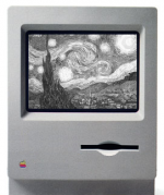
The Classic style one. Just added "Quadra" to the Classic's text.
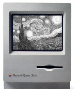
The apple horizontally lining up with the drive slot...
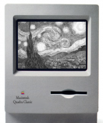
The word Macintosh lining up with the drive slot (like on a 475/605) but name silk-screened on (like an older Mac).
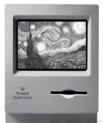
The same with "Quadra Classic" in a smaller font size on a sticky badge (like a 475/605).
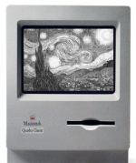
- - -
On a different topic, I've been playing with the internal components, and I can get everything to fit!
The blank one would be reminiscent of the original Mac and TAM. Only model distinction would be on the backplate.
The Classic style one. Just added "Quadra" to the Classic's text.
The apple horizontally lining up with the drive slot...
The word Macintosh lining up with the drive slot (like on a 475/605) but name silk-screened on (like an older Mac).
The same with "Quadra Classic" in a smaller font size on a sticky badge (like a 475/605).
- - -
On a different topic, I've been playing with the internal components, and I can get everything to fit!
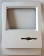
I was having a hard time telling what my textures were looking like with the different color putties I'd used, so I hit it with a light coat of primer to even out the colors. Now I can focus on filling the texture imperfections that are now much clearer.
It's beautiful. :'(
Really good job there. Really. Wish I could do that, I have some fronts but no ability.
Yeah, well...
It's kind of a Cameron Diaz sort of thing at the moment. Deceptively attractive in soft focus or from a distance, pock-marked and wrinkly up close.
I need to do some reshaping of the back of the center of the opening. The top is way too arched. And there are some serious surface smoothing issues in there. I definitely think it can be done though.
I'm consulting the art teachers at school today to see if they have any tricks for the smoothing and reshaping that need to be done.
It's kind of a Cameron Diaz sort of thing at the moment. Deceptively attractive in soft focus or from a distance, pock-marked and wrinkly up close.
I need to do some reshaping of the back of the center of the opening. The top is way too arched. And there are some serious surface smoothing issues in there. I definitely think it can be done though.
I'm consulting the art teachers at school today to see if they have any tricks for the smoothing and reshaping that need to be done.
Fabulous! Reiterative wiping/sanding of Bondo or your putty in the imperfections would be my method of choice.
Looking at your work so far, I can't but think that any lettering would be gilding the lily. The pout is an adequate homage to the Quadra within . . .
. . . so adding the Rainbow logo of the 128k in that position would keep the design as clean as can be and a more effective homage to the 128k . . .
. . . 'shop it, you'll like it!
Looking at your work so far, I can't but think that any lettering would be gilding the lily. The pout is an adequate homage to the Quadra within . . .
. . . so adding the Rainbow logo of the 128k in that position would keep the design as clean as can be and a more effective homage to the 128k . . .
. . . 'shop it, you'll like it!