

Thread
I want to do this...
Yup. That's definitely one of the contenders. Wish I hadn't already filled in the Apple divot. I might be able to rescue it if I decide to go that way. If I leave it blank I think I'll redo the backplate card with "Tenth-Anniversary Macintosh" instead of "Quadra Classic."Been messing with photoshop to try to decide where the name / apple should go.
The blank one would be reminiscent of the original Mac and TAM. Only model distinction would be on the backplate.

...
nOOOOO! mAKE A NEW DIVIT . . . MAybe even a rounded square opening for the insert of a real 128k logo patch (from a borken 128k front bezel) or from an A2 kinda bezel? It should be in the exact location as on the 128k. I especially like the notion of an inserted, flat square patch from a real 128k sunken into the ClassicCurvature. That'd be the perfect counterpoint to the added pout curvature of your hack . . .
. . . especially if it were to be parallel to the plane of the frame so the indentation is deeper on the right than the left. :approve:
p.s. i HATE cAPLOCK!!!!!!!!!!!!

p.p.s. I've been looking at the Classic II MoBo again and I think I've figured out how to add the ports you need to the FDD opening if I remove the DA-15. This hack will be a LOT more reliable than a homebrew PCB. Just let me know how long your grafted on cables need to be for an elegant installation. To answer your previous question about using the reset switches for A/B activation: It won't be any real problem at all using a TRENDnet A/B switch (small and very inexpensive) to do the dirty deed. It has two momentary switches to hotwire to the existing reset switches for I.O. choice. we can A/B switch your Sound I/O as well. If you can source the PS2 version, A/B switching ADB would be duck soup as well.
I can likely hotwire ADB onto the USB version's connectors. IIRC they're both 5v supply, so the switch would be ADB powered to boot!
@ the rest of the gang: anybody got an empty Classic Shell/Chassis you wanna swap for something from my trade goodies? }
. . . especially if it were to be parallel to the plane of the frame so the indentation is deeper on the right than the left. :approve:
p.s. i HATE cAPLOCK!!!!!!!!!!!!
p.p.s. I've been looking at the Classic II MoBo again and I think I've figured out how to add the ports you need to the FDD opening if I remove the DA-15. This hack will be a LOT more reliable than a homebrew PCB. Just let me know how long your grafted on cables need to be for an elegant installation. To answer your previous question about using the reset switches for A/B activation: It won't be any real problem at all using a TRENDnet A/B switch (small and very inexpensive) to do the dirty deed. It has two momentary switches to hotwire to the existing reset switches for I.O. choice. we can A/B switch your Sound I/O as well. If you can source the PS2 version, A/B switching ADB would be duck soup as well.
I can likely hotwire ADB onto the USB version's connectors. IIRC they're both 5v supply, so the switch would be ADB powered to boot!
@ the rest of the gang: anybody got an empty Classic Shell/Chassis you wanna swap for something from my trade goodies? }
Thanks a lot. Now I'm wandering around my classroom with a ruler like a crazed nun looking for knuckles to whack.
Measured to the edge of the inset:
The 128/512 round-rect inset Apple Logo was 25mm in from the left and 32mm up from the bottom of the chin.
The Plus inset Apple Logo was 25mm in and a whopping 55mm up.
The SE Apple was 20mm in and 10mm up.
The SE/30 Apple was 25mm in and 10mm up.
The Classic/CII Apple was 20mm in and 20mm up.
All the Apples were the same size, 15mm tall by 12mm wide,not taking into account the square round-rect around the 128's. The left side of that round-rect, and the left edge of the Apples on the Plus, SE, and Classic lined up perfectly with the vertical bezel edge of the monitor (where the monitor bezel's left angle meets the face's plane). The SE/30's Apple didn't line up horizontally with anything, as far as I can tell.
The Plus's Apple is centered vertically on the center-line of the FDD slot; the SE and SE/30's is centered vertically between the bottom of the chin and the bottom of the floppy gap. The 128/512's is set in-and-up ~14mm from the left and bottom bevels' edges (the bevel is more gradual on the bottom, so vertically longer). The Classic/CII's is just inset 2cm from the edges of the computer/chin.
All of that said... I can't decide if it should be a Quadra Classic with writing on the face, or a Tenth Anniversary Macintosh with just an apple.
Measured to the edge of the inset:
The 128/512 round-rect inset Apple Logo was 25mm in from the left and 32mm up from the bottom of the chin.
The Plus inset Apple Logo was 25mm in and a whopping 55mm up.
The SE Apple was 20mm in and 10mm up.
The SE/30 Apple was 25mm in and 10mm up.
The Classic/CII Apple was 20mm in and 20mm up.
All the Apples were the same size, 15mm tall by 12mm wide,not taking into account the square round-rect around the 128's. The left side of that round-rect, and the left edge of the Apples on the Plus, SE, and Classic lined up perfectly with the vertical bezel edge of the monitor (where the monitor bezel's left angle meets the face's plane). The SE/30's Apple didn't line up horizontally with anything, as far as I can tell.
The Plus's Apple is centered vertically on the center-line of the FDD slot; the SE and SE/30's is centered vertically between the bottom of the chin and the bottom of the floppy gap. The 128/512's is set in-and-up ~14mm from the left and bottom bevels' edges (the bevel is more gradual on the bottom, so vertically longer). The Classic/CII's is just inset 2cm from the edges of the computer/chin.
All of that said... I can't decide if it should be a Quadra Classic with writing on the face, or a Tenth Anniversary Macintosh with just an apple.
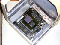
Some pictures of interior layout.
The Q605 board will be just above the bottom of the case. I'll raise it a little for air flow. The stealth stubby-board will ride in the original Classic II LoBo's rails about 3/4" above.
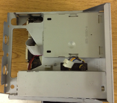
I need to either hack the LC power-supply to have longer wires, or make myself a power extension cord.
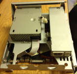
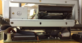
You can barely tell that there's a 1G HDD riding bat-style above the LoBo, and under the FDD's floor there. Might change this layout, but it's pretty nice so far. Lots of room above it for the monitor's messy innards.
The Q605 board will be just above the bottom of the case. I'll raise it a little for air flow. The stealth stubby-board will ride in the original Classic II LoBo's rails about 3/4" above.
I need to either hack the LC power-supply to have longer wires, or make myself a power extension cord.
You can barely tell that there's a 1G HDD riding bat-style above the LoBo, and under the FDD's floor there. Might change this layout, but it's pretty nice so far. Lots of room above it for the monitor's messy innards.
I need to play around with the spare Plus, a MicroQuadra MoBo, your Classic II MoBo and my TRENDnet A/B switch. From the looks of your pics, it seems to me like it'd be better to mount the MoBo upside down and as far forward as possible like my ShortBedTakky hack. That way you'd have more clearance for the cable adaptation runs.
What would the benefit of mounting it upside down be? It'll fit in the rails right side up, but the HDD will only fit if no board is in the rails under it. The HD also won't fit in the case under a board in the rails.
I can see maybe mounting it backwards so the 605's ports are facing forward. Then the much longer cables for video/audio/serial/ADB would only have to do a C shape 180 degree turn instead of a Z shaped over-under double 180.
A Plus will give you case bottom to LoBo celing/FDD floor clearance info, but the rails in it are much lower than a Classic's. So things will fit below a Classic's rails that will not fit under a Plus's, and things will fit above a Plus's that won't fit above a Classic's.
I can see maybe mounting it backwards so the 605's ports are facing forward. Then the much longer cables for video/audio/serial/ADB would only have to do a C shape 180 degree turn instead of a Z shaped over-under double 180.
A Plus will give you case bottom to LoBo celing/FDD floor clearance info, but the rails in it are much lower than a Classic's. So things will fit below a Classic's rails that will not fit under a Plus's, and things will fit above a Plus's that won't fit above a Classic's.
I'll play with the boards . . . not enough coffee to grok what you're saying.
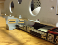
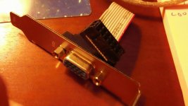
Meanwhile if anyone sights something like this adapter, let Al or myself know about it so we can get it into the FDD port of the Classic alongside the much easier to source RJ-45 jack.
Meanwhile if anyone sights something like this adapter, let Al or myself know about it so we can get it into the FDD port of the Classic alongside the much easier to source RJ-45 jack.
I'll have to look, but I might have something like that. I'm scared to go in the dungeon at the moment as it's been raining quite good today.
Couldn't find it in the dungeon, However since I have one of these from a mac mini,
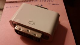
You guys can have this from my daily driver. (If I need it in the future, my son has the same video card and only uses DVI or HDMI.)
You guys can have this from my daily driver. (If I need it in the future, my son has the same video card and only uses DVI or HDMI.)
I can make one of those from parts from KC Electronics Supply. We'll probably have to cut off one of its "ears."
In fact jt, if you want to put together a parts list, I can get all kinds of fun stuff there. I already made a little Mac-video to 16 post (looks like a floppy cable, but with only 15 leads and D plug on one end) cable for getting the video out to something. A VGA version will require soldering instead of just crimping, but I can send you the bits to make it however you like.
In fact jt, if you want to put together a parts list, I can get all kinds of fun stuff there. I already made a little Mac-video to 16 post (looks like a floppy cable, but with only 15 leads and D plug on one end) cable for getting the video out to something. A VGA version will require soldering instead of just crimping, but I can send you the bits to make it however you like.
I like that type because it has a little circuit board for the connections to the ribbon cable and I could terminate the cable wherever it's convenient to hook it up to the KVM. I've got some soldertail HD-15M connectors in stock, I've got just about ever permutation of the DA-15 connector available, but no HD-15F soldertails.
I figured on savaging one side and mounting the other to the lug on one side of the DA-15F, which will need to be removed.
If you can pick up a soldertail HD-15F connector, that may be the easiest of all.
I figured on savaging one side and mounting the other to the lug on one side of the DA-15F, which will need to be removed.
If you can pick up a soldertail HD-15F connector, that may be the easiest of all.
No problem.
Belay that!
It was late, make that a solder cup connector at both ends, I've got the male, but I can keep it in stock if you snag both.
Let's see . . . forgot the other two sides of your KVM setup . . .
4 HD-15M soldercup
1 HD-15F soldercup
1 DA-15F soldercup
KVM as dioscussed
. . . If using a Mac->VGA adapter between MoBo and KVM, add . . .
1 DA-15M soldercup
1 DA-15F soldercup
. . . that ought to cover it for video.
Additional items . . .
1 sacrificial serial cable
1 sacrificial ADB cable
1 sacrificial ADB cable
1 AAUI adapter
. . . we'll still need to nail down the sound system specs.
My understanding is that you'd like to switch audio I/O along with the video when using the unit as a monitor only?
Unswitched:
1 sacrificial Mono 1/8 audio cable for microphone
1 sacrificial Stereo 1/8 audio cable for headphone jack
Switched:
TBD, but three solder cup USB connectors would keep your KVM stock . . .
. . . a soldertail (PCB) Stereo jack like the Speaker/Headphone jack can be mounted upside down to match the position of the mono microphone jack.
I'll fire up Illustrator to do a nice schematic of the adapter board connections with the KVM and a Mac adapter in the wiring harness before proceeding.
Meanwhile, gotta find that dratted Mac Plus chassis, how do you manage misplace something that big and clumsy . . . :-/
} Have you planned to install speakers on each side of the Classic's cooling vents for stereo startup chimes/MoBo sound output? :?:
It was late, make that a solder cup connector at both ends, I've got the male, but I can keep it in stock if you snag both.
Let's see . . . forgot the other two sides of your KVM setup . . .
4 HD-15M soldercup
1 HD-15F soldercup
1 DA-15F soldercup
KVM as dioscussed
. . . If using a Mac->VGA adapter between MoBo and KVM, add . . .
1 DA-15M soldercup
1 DA-15F soldercup
. . . that ought to cover it for video.
Additional items . . .
1 sacrificial serial cable
1 sacrificial ADB cable
1 sacrificial ADB cable
1 AAUI adapter
. . . we'll still need to nail down the sound system specs.
My understanding is that you'd like to switch audio I/O along with the video when using the unit as a monitor only?
Unswitched:
1 sacrificial Mono 1/8 audio cable for microphone
1 sacrificial Stereo 1/8 audio cable for headphone jack
Switched:
TBD, but three solder cup USB connectors would keep your KVM stock . . .
. . . a soldertail (PCB) Stereo jack like the Speaker/Headphone jack can be mounted upside down to match the position of the mono microphone jack.
I'll fire up Illustrator to do a nice schematic of the adapter board connections with the KVM and a Mac adapter in the wiring harness before proceeding.
Meanwhile, gotta find that dratted Mac Plus chassis, how do you manage misplace something that big and clumsy . . . :-/
}
Have you planned to install speakers on each side of the Classic's cooling vents for stereo startup chimes/MoBo sound output? :?:
Got it. I won't be able to go shopping today anyhow.
Good! I'm still editing that post! :lol:
I don't see any reason to have the audio switched. I'll be using the original single Classic II's (or maybe the Q605's) 2.25"/58mm tinny speaker for internal audio. Not exactly hi-fi. So, I can't envision a scenario where I'd want to bring audio-in to it. Whatever will be sending video into the QC will have to send its audio somewhere better
I just want the internal speaker to turn off when I use headphones/speakers, like it should.
Although... this is a later Classic II bucket, with the "audio enhancing" starburst of holes...

So, I could probably transfer that pattern to the other side, drill 31 holes, and have stereo speakers. Then it could have the Classic II's and 605's speakers all in one!
Hmmm...
I just want the internal speaker to turn off when I use headphones/speakers, like it should.
Although... this is a later Classic II bucket, with the "audio enhancing" starburst of holes...
So, I could probably transfer that pattern to the other side, drill 31 holes, and have stereo speakers. Then it could have the Classic II's and 605's speakers all in one!
Hmmm...
< not so tangent >
If you could shoehorn a pair of Q630 or 5XXX speakers with the base chambers in there . . .
. . . you'd have the most Compact/Classic/Color Classsic/Quadra startup bong/alert/internal sound system evah!!!
  )
)
In a more practical sense, if you're using the Monitor for a KVM'd Mac with stereo out, you may as well be able to pipe KVM'd stereo in for same. }
Meanwhile, back at the Banana Ranch . . .
I see why mounting the MoBo upside down in either orientation isn't really an option, because the mounting flange for the front bezel is in the way:
Your way - the hookups at the back wind conflict with the adapter due to the reduced depth
My way - the Ethernet card and ports cause conflict with the adapter due to the reduced depth
BTW, none of the other ports matter, but we need to flip the orientation of the SCSI connector with cable folds as it stands now!
I found the intact chassis, but the one already in a case works better anyway!
Are you mounting the A/B for the monitor on top of the FDD bracket, opposite the Classic's A/B remnants or replacing much of the A/B on that side?
If the former, fabbing a new, raised chassis in the CRT/FDD/AB cavern to support the monitor's A/B and to hang an underslung FDD might yield enough cubic to mount the 605 MoBo on top of the Classic's chassis leaving plenty of room for the KVM switch Adapter and various cabling underneath.
Dunno, your PSU is likely in the way . . . gotta review the whole thread. :-/
Getting the FullRes versions of all your pics to me for a local slide show would be a huge help. :approve:
If you could shoehorn a pair of Q630 or 5XXX speakers with the base chambers in there . . .
. . . you'd have the most
Compact/Classic/Color Classsic/Quadra startup bong/alert/internal sound system evah!!! ) In a more practical sense, if you're using the Monitor for a KVM'd Mac with stereo out, you may as well be able to pipe KVM'd stereo in for same. }
Meanwhile, back at the Banana Ranch . . .
I see why mounting the MoBo upside down in either orientation isn't really an option, because the mounting flange for the front bezel is in the way:
Your way - the hookups at the back wind conflict with the adapter due to the reduced depth
My way - the Ethernet card and ports cause conflict with the adapter due to the reduced depth
BTW, none of the other ports matter, but we need to flip the orientation of the SCSI connector with cable folds as it stands now!
I found the intact chassis, but the one already in a case works better anyway!
Are you mounting the A/B for the monitor on top of the FDD bracket, opposite the Classic's A/B remnants or replacing much of the A/B on that side?
If the former, fabbing a new, raised chassis in the CRT/FDD/AB cavern to support the monitor's A/B and to hang an underslung FDD might yield enough cubic to mount the 605 MoBo on top of the Classic's chassis leaving plenty of room for the KVM switch Adapter and various cabling underneath.
Dunno, your PSU is likely in the way . . . gotta review the whole thread. :-/
Getting the FullRes versions of all your pics to me for a local slide show would be a huge help. :approve:
Just checked your LowRes shots of the components and it looks possible, in a Plus there's all kinds of clearance for a mezzanine level installation.
It'd probably need to be ports front if it will work. But if it fits at all, it frees up all kinds of Cubic for cool stuff, like the KVM and those Q630 speakers pointing out the cooling vents at the bottom, leaving the case unmolested . . .
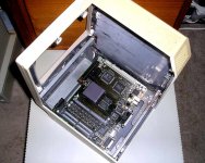
. . . the VideoPort even nestles perfectly in between the upright and the A/B...
. . . not to mention straightening out your SCSI cable! :lol:
Got 1" clearance between bottom of FDD & Chassis? :?:
edit: You know something . . . you're sorely tempting me to dial this visible "Mac" hack back back down from an ATOM to a ZipMac+ColorQuadra here, buddy!)
It'd probably need to be ports front if it will work. But if it fits at all, it frees up all kinds of Cubic for cool stuff, like the KVM and those Q630 speakers pointing out the cooling vents at the bottom, leaving the case unmolested . . .
. . . the VideoPort even nestles perfectly in between the upright and the A/B...
. . . not to mention straightening out your SCSI cable! :lol:
Got 1" clearance between bottom of FDD & Chassis? :?:
edit: You know something . . . you're sorely tempting me to dial this visible "Mac" hack back back down from an ATOM to a ZipMac+ColorQuadra here, buddy!
)
quick and dirty ASCII art representation of how I have it arranged so far:
''_________________
/ /|
/ / |
| / |
| ___/ VGA |
| =C___ CRT |
| \ |
| \ |
| \ |
| [Analog board]_\| <-- VGA PSU/AB suspended between FDD and CRT
|__[LC PSU & FDD]__| <-- The Q605/LC475 power supply next to the FDD on top of mezzanine
[stealth] [HDD] | <-- Stealth board in rails, HDD hanging from mezzanine
|__[Logic Board]_| <-- LoBo pretty much on floor of case
I think I can come up with some nice bits and parts that'll make my arrangement fit.
Is the only worry the length/depth of the connectors? The RJ45 is practically flush, and here're a couple of the things I'm already sending you:
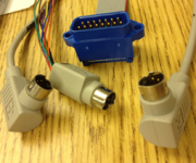
Those are right angle (one left, one right) ADBs, my straight-to-ribbon DA-15M, and a stripped to the fat-part 8-wire serial. All are less than 1.25 inches deep/long.
P.S. would the crimp to ribbon type connectors be preferable to solder-cup if they're available?
''_________________
/ /|
/ / |
| / |
| ___/ VGA |
| =C___ CRT |
| \ |
| \ |
| \ |
| [Analog board]_\| <-- VGA PSU/AB suspended between FDD and CRT
|__[LC PSU & FDD]__| <-- The Q605/LC475 power supply next to the FDD on top of mezzanine
[stealth] [HDD] | <-- Stealth board in rails, HDD hanging from mezzanine
|__[Logic Board]_| <-- LoBo pretty much on floor of case
I think I can come up with some nice bits and parts that'll make my arrangement fit.
Is the only worry the length/depth of the connectors? The RJ45 is practically flush, and here're a couple of the things I'm already sending you:
Those are right angle (one left, one right) ADBs, my straight-to-ribbon DA-15M, and a stripped to the fat-part 8-wire serial. All are less than 1.25 inches deep/long.
P.S. would the crimp to ribbon type connectors be preferable to solder-cup if they're available?
If the LoBo is on the floor, pretty much the entire rail area is available for whatever stealth/KVM weirdness we're doing. The tallest part of the LoBo is the HDD power connector at about 1.5 inches tall all the way in the front driver's side corner. There will not be enough vertical room to attach it if it is upside down in the rails, and no advantage to having it upside down if it is above the rails.
I don't think the LoBo will fit above the Classic II's mezzanine without some serious metalwork (that I'd rather not do). With the FDD and PSU in there, there is about a 1.5"x 4"x 5.5" space for the bulk of the KVM/Mac->VGA adapter, though. I'll need to have space around the plug/switch assembly on the old AB for power distribution to the two PSUs. I'm thinking I'll just unsolder everything but the plug and switch, and use it like an untraced mounting board.
If the audio-in will be no hassle to add, it's fine with me, but it's not at all something I would miss if we skipped it.
I don't think the LoBo will fit above the Classic II's mezzanine without some serious metalwork (that I'd rather not do). With the FDD and PSU in there, there is about a 1.5"x 4"x 5.5" space for the bulk of the KVM/Mac->VGA adapter, though. I'll need to have space around the plug/switch assembly on the old AB for power distribution to the two PSUs. I'm thinking I'll just unsolder everything but the plug and switch, and use it like an untraced mounting board.
If the audio-in will be no hassle to add, it's fine with me, but it's not at all something I would miss if we skipped it.
1/10 spacing IDC cable won't translate into three row HD-15 AFAIK, maybe there's a special denser spacing cable to do it, but I've yet to see it.
Solder cup is probably better on the 10bT side of the FDD access panel, it'll be narrower overall.
If you move the Monitor's A/B to the side opposite the Classic A/B would you have room for that and to mount your 605 above board on top if the FDD & PSU?
I'm really diggin' the subterranean stereo Compact hack! ;D
Solder cup is probably better on the 10bT side of the FDD access panel, it'll be narrower overall.
If you move the Monitor's A/B to the side opposite the Classic A/B would you have room for that and to mount your 605 above board on top if the FDD & PSU?
I'm really diggin' the subterranean stereo Compact hack! ;D
Unfortunately, the AB is designed to ride below the CRT and none of the leads are long enough to move it more than an inch or two in any direction. It wont go to either side without some wire splicing , which I'd rather avoid.
There's plenty of room to the sides of the CRT and I wouldn't mind at all copying the starburst holes to the other side of the case for stereo. I don't have a 630 to yank speakers out of though.
There's plenty of room to the sides of the CRT and I wouldn't mind at all copying the starburst holes to the other side of the case for stereo. I don't have a 630 to yank speakers out of though.
Duly noted. Somebody must have a spare pair of speakers from a 5xxx RoadApple that they can sell you really cheap.
edit: got room on the ceiling of the case for that A/B and cooling vent clearance? :?: MacPortrait is your friend. }
edit: got room on the ceiling of the case for that A/B and cooling vent clearance? :?: MacPortrait is your friend. }
I've bought entire machines for dumber reasons than to strip out the speakers
I'll find something.
I'll find something.
the 630 series only have one speaker each, the 5xxx series have stereo.
Will that be a whole other powered sub-system? Are the 5x00 speakers passive, or will they need their own 5V supply? I can probably cannibalize some power from elsewhere in the case if so.
Maybe we need a whole other SuperAudioCompactMonitor hack. All that's in the compact case is a killer sound system and a XGA flat screen. Two ports on the back, no annoying LoBo or drives to have to work around
Maybe we need a whole other SuperAudioCompactMonitor hack. All that's in the compact case is a killer sound system and a XGA flat screen. Two ports on the back, no annoying LoBo or drives to have to work around
:lol: Great notion for a Vhack type hardware development project, A/Vquarium kinda deal.
They're line level like all the speakers before them, IIRC.
They're line level like all the speakers before them, IIRC.
Is this going to be a color or grayscale system?
Which one? :lol:
Al's current project is grayscale.
Al's current project is grayscale.
oP: The CRT monochrome monitor accepts regular color SVGA and renders them as grayscale. You aren't supposed to be able to perceive a difference between thousands and 256 colors in grayscale, but I seem to be able to, especially in images.