

Thread
I want to do this...
Use a switched socket; it's a standard part. There is a switch inside that diverts the signal lines to another output when a plug is not present.
580/630 boards are Quadra all the way and very cool. The RoadApple PPCs were perfectly good 580/630 family boards with PPC CPUs slapped onto them with malice intent.
The problem you'd have with the 630 board would be size. There's only one way to get it to fit into a Compact and it ain't stealthy in the least. Is the 580 board the same as the Q630 board or is it a bit shorter from front to back than the 630 board? If so, that might work out for a stealth hack.
The problem you'd have with the 630 board would be size. There's only one way to get it to fit into a Compact and it ain't stealthy in the least. Is the 580 board the same as the Q630 board or is it a bit shorter from front to back than the 630 board? If so, that might work out for a stealth hack.
First, I haven't actually begun rework on the port replicator, so that's no time wasted whatsoever. Procrastination pays! ;D
Second, I reread your post while I'm actually awake and see that you've already covered the point I made last night. :I
Third, I downloaded the Service Manuals for the 575 and 580, interesting little board that 575! :approve:
I see why you might want to give the 575 MoBo a try. Have you got one already? Is it safe to assume that the CC Crowd has already figured out how to adapt the Analog Board connector signals(?) to provide VGA output? That's the only fly I see in this ointment for your VGA-Classic. ISTR some of the CC hacks including a display upgrade to 640x480, so that might not be much of a problem in that case.
The power adaptation doesn't seem like much of a problem . . . 8-o . . . hrmmm . . . } . . .
. . .
. . . now that I think about it, eschewing use of the metal chassis and replacing it with a custom plexi chassis, as we discussed, opens up the possibility of stealth mounting a 630/6500 MoBo! By angling it up from the bottom front (MedusaMess) to approximately the level of the power switch (backplane) with the board inverted, there should still be room for the FDD! The PSU would need to be mounted sideways, just above the port replicator with the KVM switch in front.
Using the 580/630 board sidesteps A/B signal conversion, retaning 800x600 VGA output, something lost(?) in going the 575 route!
Second, I reread your post while I'm actually awake and see that you've already covered the point I made last night. :I
Third, I downloaded the Service Manuals for the 575 and 580, interesting little board that 575! :approve:
I see why you might want to give the 575 MoBo a try. Have you got one already? Is it safe to assume that the CC Crowd has already figured out how to adapt the Analog Board connector signals(?) to provide VGA output? That's the only fly I see in this ointment for your VGA-Classic. ISTR some of the CC hacks including a display upgrade to 640x480, so that might not be much of a problem in that case.
The power adaptation doesn't seem like much of a problem . . . 8-o . . . hrmmm . . . }
. . .. . . now that I think about it, eschewing use of the metal chassis and replacing it with a custom plexi chassis, as we discussed, opens up the possibility of stealth mounting a 630/6500 MoBo! By angling it up from the bottom front (MedusaMess) to approximately the level of the power switch (backplane) with the board inverted, there should still be room for the FDD! The PSU would need to be mounted sideways, just above the port replicator with the KVM switch in front.
Using the 580/630 board sidesteps A/B signal conversion, retaning 800x600 VGA output, something lost(?) in going the 575 route!
BINGO!!! [] ]'>
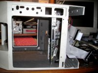
With judicious trimming of the MedusaMess Connector, the CommSlot & TV Tuner Cards (connectorectomy required for that one) they should fit just fine!
One PCI Card, no problem! There's a possibility of using two as they're inset far enough into the drawer for it to work. [}] ]'>
This 630 hack is duck soup, whatchathink, Al?
edit: the ClassicCarcass in the pic is from the MacintoshClassicIIIColorTVp™ where I've done the ShortBedTakkyHACK™. That long delayed project is soon (a relative term) to be completed as I've now got a diamond blade wet tile saw waiting fabrication of a cutoff jig for lopping the back off the dead CRT/rear projection screen. One of these days . . .
] ]'>With judicious trimming of the MedusaMess Connector, the CommSlot & TV Tuner Cards (connectorectomy required for that one) they should fit just fine!
One PCI Card, no problem! There's a possibility of using two as they're inset far enough into the drawer for it to work. [}
] ]'>This 630 hack is duck soup, whatchathink, Al?
edit: the ClassicCarcass in the pic is from the MacintoshClassicIIIColorTVp™ where I've done the ShortBedTakkyHACK™. That long delayed project is soon (a relative term) to be completed as I've now got a diamond blade wet tile saw waiting fabrication of a cutoff jig for lopping the back off the dead CRT/rear projection screen. One of these days . . .
Heh. I'm trying to go closer to stock than the 580/630 angled hack would allow for Can't wait to see yours in action though! The only benefit I can see of a 580/630 board would be the video resolution, but I'm not sure all the 'orrible 'acking necessary would be worth the extra pixels on board (and I wouldn't be surprised, the 475 and 575 boards being so similar, if there were hidden resolutions in there somewhere...) (Also I suppose it would allow me to "upgrade" it to a 5x00 board, but that's just cruel.)
I finally had a LC sized board and my boardless ColorClassicCarcass in the same place at the same time. The LCIII+ board slid in like it was made for it.
The only downside to the monochrome-Mystic idea is the difficulty of sourcing the board itself. I can get the ribbon cable out or one of my bins if I have to.
I'm leaning towards this being the future of this project.
I'll post some pictures of the much-refined facial plastic-surgery when I get a minute this weekend (or, you know, soonish). I'm almost ready to paint it Platinum
Can't wait to see yours in action though! The only benefit I can see of a 580/630 board would be the video resolution, but I'm not sure all the 'orrible 'acking necessary would be worth the extra pixels on board (and I wouldn't be surprised, the 475 and 575 boards being so similar, if there were hidden resolutions in there somewhere...) (Also I suppose it would allow me to "upgrade" it to a 5x00 board, but that's just cruel.)I finally had a LC sized board and my boardless ColorClassicCarcass in the same place at the same time. The LCIII+ board slid in like it was made for it.
The only downside to the monochrome-Mystic idea is the difficulty of sourcing the board itself. I can get the ribbon cable out or one of my bins if I have to.
I'm leaning towards this being the future of this project.
I'll post some pictures of the much-refined facial plastic-surgery when I get a minute this weekend (or, you know, soonish). I'm almost ready to paint it Platinum
Oh man! I totally forgot about this thing! I can have the internal video just plug and play!
I'm gonna go beg for a 575 board now. Dang! I thought I was done pouring funds into this idea.
I'm gonna go beg for a 575 board now. Dang! I thought I was done pouring funds into this idea.
Do you need one of those? I have one in the scrap box here.
I've been collecting parts, and have a 575 connector/ribbon-loom combo (from a badly shipped parts machine) on the way.
I can find the Takky (630 SCSI + IDE) loom schematic easily. Does anyone know where to find the schematic for the 5xx or CC (SCSI only) series loom? Google and I can't find the right terms with which to search.
Seems like a LOT of Color Classic info bit the dust in 2012. The ColourClassicFAQ and tesco.net are gone from the real web (yay wayback-machine!). I'm sure somebody besides myself would like to have this info archived/mirrored.
Uniserver is recapping my 575 board as we speak (and will get it to me when I figure out how to properly package his trade!), so I'm beginning to get excited again about the possibilities of this project!
I can find the Takky (630 SCSI + IDE) loom schematic easily. Does anyone know where to find the schematic for the 5xx or CC (SCSI only) series loom? Google and I can't find the right terms with which to search.
Seems like a LOT of Color Classic info bit the dust in 2012. The ColourClassicFAQ and tesco.net are gone from the real web (yay wayback-machine!). I'm sure somebody besides myself would like to have this info archived/mirrored.
Uniserver is recapping my 575 board as we speak (and will get it to me when I figure out how to properly package his trade!), so I'm beginning to get excited again about the possibilities of this project!
State of the project:
Real Life is backing off a bit, so I'm getting a chance to evaluate ideas and get things in line to actually bring this to a close.
Previously I was working with a Q605 board that I was going to hide under a cut down and thoroughly re-jiggered Classic II board for ports in an unmodified rear case. Trash80toHP_Mini was going to make the stealth ports board for me, and pop in a KVM switch so I could use the cool little monitor with any computer, not just the 605 lobo.
All in all, lots of fun ideas, but too complex. All those parts, and a donor Performa 460 case, will make a very nice LC475/33. No real loss at all.
---
Currently I've decided to go simpler on the internal electronics, by going with an LC575's lobo and ribbon-connectors, and slightly more complex on the body-work by either modifying the stock Classic II's rear panel to account for the new port positions on the 575 board, or with a Color Classic Mystic-style rear door from the shaved down 575's. Either way there's lots of opportunity for me to mess that up badly. Luckily I happen to have a spare Classic bucket for back up.
Getting video out of the ribbon-loom will be my next challenge. I'm hoping that, since the Analog Board connections were unmodified whenever people shoehorned 5/6x00 boards into Color Classics, the AB schematics and diagrams for Takky hacks will be helpful here. I need to decide if I'm going to cut off the edge connector, take those signals out to a regular Mac 15-pin connector, then use an adapter to get it to the monitor's VGA connector, or if I should go the elegant route and make a little board that slides into the edge connector, does the conversion, and just sends the signals straight to the monitor's AB connector. We'll see how much spare volume I have to play with inside the case. Elegant will take more effort but way less room.
The 575 ribbon loom also has an extra SCSI ribbon/edge-connector for the CD-ROM drive in the 5xx machines. I think I'll just hack it off. I'm also strongly considering putting a regular 50-pin connector (and 4-pin molex plug) on the end of the SCSI cable I'm keeping instead of the edge connector for the slide in HDD/sled system in the 5xx series. I really wish I still had a stock CC ribbon-connector set up. Anybody do a Takky hack and have an old CC-loom in a drawer somewhere?
I still want to mirror the sunburst of holes on the CCII's left side onto its right and have stereo.
I'm still planning to use the LC power supply, since I'm not adding any new power-thirsty devices to the system. It should run the lobo, floppy, and HDD in this just like it did in the LC. I need to do some simple wiring to supply power to the monitor and LC power supply from the case's power socket and switch (I'm going to unsolder everything else from the analog board and just use it as a place to mount the LC PS and monitor AB).
I'm going to print the rear case sticker, and front Quadra Classic sticker. I need to go to Kinkos and see what my options are for this.
The body work on the front is mostly done. I still have some sanding to do, but the pout looks good, and the paint color looks close. I might mess with the paint formula a bit. If I wind up doing major body work on the back, that'll need finishing too.
TL;DR - Still working on this. Send me a Color Classic ribbon/connector-loom if you have one.
Real Life is backing off a bit, so I'm getting a chance to evaluate ideas and get things in line to actually bring this to a close.
Previously I was working with a Q605 board that I was going to hide under a cut down and thoroughly re-jiggered Classic II board for ports in an unmodified rear case. Trash80toHP_Mini was going to make the stealth ports board for me, and pop in a KVM switch so I could use the cool little monitor with any computer, not just the 605 lobo.
All in all, lots of fun ideas, but too complex. All those parts, and a donor Performa 460 case, will make a very nice LC475/33. No real loss at all.
---
Currently I've decided to go simpler on the internal electronics, by going with an LC575's lobo and ribbon-connectors, and slightly more complex on the body-work by either modifying the stock Classic II's rear panel to account for the new port positions on the 575 board, or with a Color Classic Mystic-style rear door from the shaved down 575's. Either way there's lots of opportunity for me to mess that up badly. Luckily I happen to have a spare Classic bucket for back up.
Getting video out of the ribbon-loom will be my next challenge. I'm hoping that, since the Analog Board connections were unmodified whenever people shoehorned 5/6x00 boards into Color Classics, the AB schematics and diagrams for Takky hacks will be helpful here. I need to decide if I'm going to cut off the edge connector, take those signals out to a regular Mac 15-pin connector, then use an adapter to get it to the monitor's VGA connector, or if I should go the elegant route and make a little board that slides into the edge connector, does the conversion, and just sends the signals straight to the monitor's AB connector. We'll see how much spare volume I have to play with inside the case. Elegant will take more effort but way less room.
The 575 ribbon loom also has an extra SCSI ribbon/edge-connector for the CD-ROM drive in the 5xx machines. I think I'll just hack it off. I'm also strongly considering putting a regular 50-pin connector (and 4-pin molex plug) on the end of the SCSI cable I'm keeping instead of the edge connector for the slide in HDD/sled system in the 5xx series. I really wish I still had a stock CC ribbon-connector set up. Anybody do a Takky hack and have an old CC-loom in a drawer somewhere?
I still want to mirror the sunburst of holes on the CCII's left side onto its right and have stereo.
I'm still planning to use the LC power supply, since I'm not adding any new power-thirsty devices to the system. It should run the lobo, floppy, and HDD in this just like it did in the LC. I need to do some simple wiring to supply power to the monitor and LC power supply from the case's power socket and switch (I'm going to unsolder everything else from the analog board and just use it as a place to mount the LC PS and monitor AB).
I'm going to print the rear case sticker, and front Quadra Classic sticker. I need to go to Kinkos and see what my options are for this.
The body work on the front is mostly done. I still have some sanding to do, but the pout looks good, and the paint color looks close. I might mess with the paint formula a bit. If I wind up doing major body work on the back, that'll need finishing too.
TL;DR - Still working on this. Send me a Color Classic ribbon/connector-loom if you have one.
Yeah. In spite of what the Ebay auction I sited advertised, this thing only works on 5x00 boards.
So... yeah. There's that.
Progress... in the form of gathering a bunch of the parts into the same room.
The 575 board and end-connector will be perfect. Like, frighteningly perfect. Like, maybe the original Color Classic was supposed to be in the Classic II chassis perfect. All I need to do is mark where the notches in the sheet metal (for the end-connector to slide into) should be and have my brother-in-law punch them out for me.
There are a couple of metal loop standoffs on the bottom of the board that I'll need to nip to let it slide in. There is no way anything will be useful in the comm-slot :-/ There is just barely (you might say: exactly) enough clearance for the LCPDS card though, so it will be networkable.
This connector/cable-loom is way too much for this project. I really need an original Color Classic loom with a single regular 50-pin socket instead of the card-end silliness. I can make this work, though. I hope.
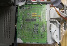
The 575 board and end-connector will be perfect. Like, frighteningly perfect. Like, maybe the original Color Classic was supposed to be in the Classic II chassis perfect. All I need to do is mark where the notches in the sheet metal (for the end-connector to slide into) should be and have my brother-in-law punch them out for me.
There are a couple of metal loop standoffs on the bottom of the board that I'll need to nip to let it slide in. There is no way anything will be useful in the comm-slot :-/ There is just barely (you might say: exactly) enough clearance for the LCPDS card though, so it will be networkable.
This connector/cable-loom is way too much for this project. I really need an original Color Classic loom with a single regular 50-pin socket instead of the card-end silliness. I can make this work, though. I hope.
Moving on, I will need to get the video signals out of the loom's Analog Board connector.
The following is stolen from the Frogeye link earlier in this thread.

Analog
Connector/
Ribbon
Position Signal
-------------------------
1 = -12 V input
2 = GND
5 = ADB Power supply
6 = GND
7 = Power off command
8 = GND
9 = Composite signal out*
10 = GND
11 = BLUE out*
12 = GND
13 = GREEN out*
14 = GND
15 = RED out*
17 = Brightness control output
18 = GND
19 = Contrast control output
20 = Monitor ID 2*
21 = Audio in (Mic)
22 = GND
23 = +5 V
24 = Monitor ID 1*
25 = Monitor ID 0*
28 = Audio out ®*
29 = GND*
30 = Audio out (L)*
31 = GND*
37 = Sound amplifier control output
My assumption is that I can follow the ribbon cable back to the logic board connector and take the signals (video and audio, *'d above) right off the main connector, and not have the analog board connector any more at all.
Since I'm not using the control panels that the CC/5xx/6xx machines had on the front, I shouldn't have to connect them to anything from the logic board connector, right?
Then I can take the appropriate +12 V, +5 V, and GND signals off the LC-475 power supply right into the logic board connector.
I'm going to remove the superflous CD-ROM cabling, and possibly crimp a standard SCSI 50-position connector and 4-position molex connector on the end of the SCSI HD ribbon. That will almost make this 550 loom a CC loom!
The following is stolen from the Frogeye link earlier in this thread.
Analog
Connector/
Ribbon
Position Signal
-------------------------
1 = -12 V input
2 = GND
5 = ADB Power supply
6 = GND
7 = Power off command
8 = GND
9 = Composite signal out*
10 = GND
11 = BLUE out*
12 = GND
13 = GREEN out*
14 = GND
15 = RED out*
17 = Brightness control output
18 = GND
19 = Contrast control output
20 = Monitor ID 2*
21 = Audio in (Mic)
22 = GND
23 = +5 V
24 = Monitor ID 1*
25 = Monitor ID 0*
28 = Audio out ®*
29 = GND*
30 = Audio out (L)*
31 = GND*
37 = Sound amplifier control output
My assumption is that I can follow the ribbon cable back to the logic board connector and take the signals (video and audio, *'d above) right off the main connector, and not have the analog board connector any more at all.
Since I'm not using the control panels that the CC/5xx/6xx machines had on the front, I shouldn't have to connect them to anything from the logic board connector, right?
Then I can take the appropriate +12 V, +5 V, and GND signals off the LC-475 power supply right into the logic board connector.
I'm going to remove the superflous CD-ROM cabling, and possibly crimp a standard SCSI 50-position connector and 4-position molex connector on the end of the SCSI HD ribbon. That will almost make this 550 loom a CC loom!
Way back in the day, I had an old PM5300 with a dead flyback and no video connector, I was able to pull out the video signals from the loom and run it into a VGA monitor, and never had any issues. it was a huge mess. but it worked.
I'm lost, is this still going into the pout lipped Classic? Did you switch to the 575 board for anything but extra room?
Yup. As long as this idea has taken to come to reality, coming up on a year or so, I've had plenty of time to change everything about the insides.
The 575 board is still very much true to the original concept. Still a 33MHz Quadra brain, still capable of grayscale VGA+, Ethernet, etc. But I (we) were jumping through all kinds of hoops to get the 605's brain in there without changing up the case's bucket. I decided after the relative success of the face-lift, a butt-lift wouldn't be too traumatic, so I (we) no longer had to worry about making a stealth port board. Everything about the 575 fits so much better in the original rails, like to the point (as I mentioned earlier) that I wouldn't be surprised if the CC board was intended for something very-much-closer to the original Classic case in the first place. I'm already relatively comfortable with manipulating the wire-loom from my decade-ago adventure in Zip-ifying a CC, so I can hopefully accomplish most of the rest of this myself.
My question now: The loom has composite sync. How shall I deal with that?
The 575 board is still very much true to the original concept. Still a 33MHz Quadra brain, still capable of grayscale VGA+, Ethernet, etc. But I (we) were jumping through all kinds of hoops to get the 605's brain in there without changing up the case's bucket. I decided after the relative success of the face-lift, a butt-lift wouldn't be too traumatic, so I (we) no longer had to worry about making a stealth port board. Everything about the 575 fits so much better in the original rails, like to the point (as I mentioned earlier) that I wouldn't be surprised if the CC board was intended for something very-much-closer to the original Classic case in the first place. I'm already relatively comfortable with manipulating the wire-loom from my decade-ago adventure in Zip-ifying a CC, so I can hopefully accomplish most of the rest of this myself.
My question now: The loom has composite sync. How shall I deal with that?
Got it, maybe? You're replacing the port section of the Classic's derriere with that of the 575?
As far as your video predicament goes, methinks the video-out card of a Quadra 630 or its RoadApple 6xxx offspring wired up to the loom might be all that you'd need.
Do I recall you saying something about not being able to use the Comm Slot for EtherNet? You(we :lol: ) just can't have that now can we?
There's got to be a way to fit the KVMage in there much more easily with all that extra room and customized @$$plate. [ ] ]'>
] ]'>
I've got a Radius Pivot LC Card of some sort for a second monitor somewhere around here. It's not in the Magic Plastic Shoe Box of PDS Goodness, so I'll have to check the pile-o-LC slotted macs. I'm guessing macmetex still has some of these kicking around.
Heh! [}] ]'>
As far as your video predicament goes, methinks the video-out card of a Quadra 630 or its RoadApple 6xxx offspring wired up to the loom might be all that you'd need.
Do I recall you saying something about not being able to use the Comm Slot for EtherNet? You(we :lol: ) just can't have that now can we?
There's got to be a way to fit the KVMage in there much more easily with all that extra room and customized @$$plate. [
] ]'>I've got a Radius Pivot LC Card of some sort for a second monitor somewhere around here. It's not in the Magic Plastic Shoe Box of PDS Goodness, so I'll have to check the pile-o-LC slotted macs. I'm guessing macmetex still has some of these kicking around.
Heh! [}
] ]'>
Yup. This'll pretty much be a monochrome Takky hack. (Blakky?) Some careful carving on the Classic rear end and the 575 back-door should result in a decent rear view. (Cool side effect, I should be able to slide out the logic-board like a real CC-6500 Mac).
I'm really hoping to use the pseudo-LCPDS slot for Ethernet. It'll take some heavy duty metal-cutting to make a place for the Comm-Slot to work. Might not be the worst though, it would make the butt-lift part of the plastic-surgery better looking if the com-slot port was populated/populatable.
If I go with a LCPDS vid-card, I'm right back where I was with having the video port sticking out the back. Might as well just use the 605 board at that point. There were some composite video out Macs (IIcx/ci?) that were able to be adapter'd to VGA. I'll have to look into how those adapters were wired.
I'm really hoping to use the pseudo-LCPDS slot for Ethernet. It'll take some heavy duty metal-cutting to make a place for the Comm-Slot to work. Might not be the worst though, it would make the butt-lift part of the plastic-surgery better looking if the com-slot port was populated/populatable.
If I go with a LCPDS vid-card, I'm right back where I was with having the video port sticking out the back. Might as well just use the 605 board at that point. There were some composite video out Macs (IIcx/ci?) that were able to be adapter'd to VGA. I'll have to look into how those adapters were wired.
I know somebody who likes playing with his pneumatic sheet metal working tool collection almost as much as his Japanese pull saws. [] ]'>
I don't understand the problem with the video in port, it should be an easy hack if you're using a Comm Slot NIC and an LC VidCard . . .
. . . remove one of the mounting lug nuts on the VidCard . . .
. . . drill the lug nut hole in the DA-19 connector/Backplane plate out to 3/16" diameter . . .
. . . remove the mounting bolt from your VGA adapter for the LC VidCard . . . funnel shaped Mac VDO type adapter preferably
. . . drill the mounting bolt hole of the adapter out to the same diameter . . .
. . . lop off one end of a thin VGA cable like the one in my hand . . .
. . . feed it through the 3/16" holes and terminate it to a 15-20 pin male<->female plug kind of deal . . .
. . . terminate the short, lopped off part of the VGA cable to the matching socket/plug . . .
All you need to do is unplug the connection and when you pull out your drawer. and it's free and clear.
The card will be removable from the MoBo as well. One mounting lug is plenty for the VGA adapter, it seems like a quarter of my macs are missing one side or the other. Remove the RFI shielding from the LC Card cutout and the Mac VDO fits through vertically just fine. Horizontally you'll only only need to file the tiniest smidge off each side of the plastic shroud. The VGA cable's connector and Ferrite ring on the cable fit through without modification.
If you decide to change out the LC PDS Card, all you need to do is unhook the VGA-out cable from the adapter, unscrew the intact mounting bolt of the VGA adapter, pull through a bit of the slack on the VGA-in cable, pop off the card and the feed the VGA Adapter and its VGA cable tail through the slot access hole.
Did I mention the guy I know with the Japanese pull saws has pneumatic drills, a thin VGA cable and a Mac VDO adapter? [}] ]'>
] ]'>I don't understand the problem with the video in port, it should be an easy hack if you're using a Comm Slot NIC and an LC VidCard . . .
. . . remove one of the mounting lug nuts on the VidCard . . .
. . . drill the lug nut hole in the DA-19 connector/Backplane plate out to 3/16" diameter . . .
. . . remove the mounting bolt from your VGA adapter for the LC VidCard . . . funnel shaped Mac VDO type adapter preferably
. . . drill the mounting bolt hole of the adapter out to the same diameter . . .
. . . lop off one end of a thin VGA cable like the one in my hand . . .
. . . feed it through the 3/16" holes and terminate it to a 15-20 pin male<->female plug kind of deal . . .
. . . terminate the short, lopped off part of the VGA cable to the matching socket/plug . . .
All you need to do is unplug the connection and when you pull out your drawer. and it's free and clear.
The card will be removable from the MoBo as well. One mounting lug is plenty for the VGA adapter, it seems like a quarter of my macs are missing one side or the other. Remove the RFI shielding from the LC Card cutout and the Mac VDO fits through vertically just fine. Horizontally you'll only only need to file the tiniest smidge off each side of the plastic shroud. The VGA cable's connector and Ferrite ring on the cable fit through without modification.
If you decide to change out the LC PDS Card, all you need to do is unhook the VGA-out cable from the adapter, unscrew the intact mounting bolt of the VGA adapter, pull through a bit of the slack on the VGA-in cable, pop off the card and the feed the VGA Adapter and its VGA cable tail through the slot access hole.
Did I mention the guy I know with the Japanese pull saws has pneumatic drills, a thin VGA cable and a Mac VDO adapter? [}
] ]'>
I may take you up on carving a chassis-channel for the comm-slot, but I'm going to exhaust my options with the on-board 575 video before I go shopping for more cards.
If i wanted to pipe cables back into the case, I would just use the 605 board and save the hassle of messing with the wiring loom.
Or... damn it ...use the 605 board, have a VGA-in port for the monitor up in the Classic's adjustment panel area (where the 128-Plus's battery compartment was), and then I wouldn't need to worry about a KVM. Just a nice thin custom/perfect length DA-15 to HD-15 cable to send video up from the Quadra when wanted, and a cable swap away from being an external monitor for anything.
If I decide to abandon the original concept of "what a '94 Mac Classic should've been," I'll do that. I really like the idea of it being more than just a cosmetic hack. A complete product. I'm all philosophical about it
If i wanted to pipe cables back into the case, I would just use the 605 board and save the hassle of messing with the wiring loom.
Or... damn it ...use the 605 board, have a VGA-in port for the monitor up in the Classic's adjustment panel area (where the 128-Plus's battery compartment was), and then I wouldn't need to worry about a KVM. Just a nice thin custom/perfect length DA-15 to HD-15 cable to send video up from the Quadra when wanted, and a cable swap away from being an external monitor for anything.
If I decide to abandon the original concept of "what a '94 Mac Classic should've been," I'll do that. I really like the idea of it being more than just a cosmetic hack. A complete product. I'm all philosophical about it
Cool beans, loopback sounds good, but KVM . . .
. . . I just can't leave that kind of challenge alone. :
< . . . wonders about suggesting an external KVM setup to KIS . . . nah! } >
. . . I just can't leave that kind of challenge alone. :
< . . . wonders about suggesting an external KVM setup to KIS . . . nah! }
>The onboard video will be better anyway, it's all about having two screens, now a GS Classic/Color FPD LCD combo . . . ;D
As I mentioned in the WTB thread, I've hit a snag and may have to reconstruct the %*$#@ 550 wiring loom I have. I've taken the SCSI ribbon off of a Color Classic connector and replaced it before, so I stupidly assumed I could repeat the process with the 550's. Stripped several metal contacts out of the connector. I said bad words. There are plenty of spares in the mess here, but reconstructing it will be a bummer. I really wanted to be done by the 11th of Dec.
In good news: the sanding is done. The face is ready to paint. I'll share pics when it's beautiful.
I need to do some bucket plastic surgery now. I'm going to cut out a door sized hole in the back for the cut down port cover from the 575, and drill the 31 hole starburst in the right side for the other stereo speaker.
I've decided to not make a channel for the comm-slot in the metal chassis. It would weaken the chassis, and there's not really room for it on the back face of the bucket without moving the power port and switch. I do still need to notch the chassis where the board-wide connector will need to lock in. I'll do the bucket work first so everything lines up perfectly.
I need to decide if I'm going to cut down the analogue board to just the power port and switch, or if I'm going to just float all the unnecessary electronics off of it leaving a full sized but mostly empty green board on the left side of the case. Either way I need to lose all those extra bits for space. I may be able to mount the HDD on the cleared off AB.
Then paint the plastics, cram everything in there and pray I didn't ruin anything in the year this hack's taking.
In good news: the sanding is done. The face is ready to paint. I'll share pics when it's beautiful.
I need to do some bucket plastic surgery now. I'm going to cut out a door sized hole in the back for the cut down port cover from the 575, and drill the 31 hole starburst in the right side for the other stereo speaker.
I've decided to not make a channel for the comm-slot in the metal chassis. It would weaken the chassis, and there's not really room for it on the back face of the bucket without moving the power port and switch. I do still need to notch the chassis where the board-wide connector will need to lock in. I'll do the bucket work first so everything lines up perfectly.
I need to decide if I'm going to cut down the analogue board to just the power port and switch, or if I'm going to just float all the unnecessary electronics off of it leaving a full sized but mostly empty green board on the left side of the case. Either way I need to lose all those extra bits for space. I may be able to mount the HDD on the cleared off AB.
Then paint the plastics, cram everything in there and pray I didn't ruin anything in the year this hack's taking.
Was the analog board from a Classic I or II?
I'd be interested in all the "unnecessary electronics".
Meanwhile, I'm looking forward to pictures!
c
I'd be interested in all the "unnecessary electronics".
Meanwhile, I'm looking forward to pictures!
c
PM sent!
I still don't understand why you don't just desloder that entire connector and then hardwire every signal to where it's supposed to go. They're all lined up for you to use ribbon cable wired directly into the through holes in every case.
:?:
:?:
You mean on the 605 board? Yeah that would work, and if this 575 loom trick doesn't work out I will probably go back to that. It's just so elegant to have the back door and the slide in lobo. I'm kind of in love with this 575 board at the moment, but if the video issues are too big a deal, I'll go back to the 605 board. The port holes would be much harder to get right. I don't have a good LC butt to graft on a Classic case.
Just a paint job and decals away... (on the outside)
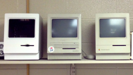
(The SE got its sticker after being rescued from it's position as a doorstop. Worked well at the time; needs a recap now. :-/ )
(The SE got its sticker after being rescued from it's position as a doorstop. Worked well at the time; needs a recap now. :-/ )
Teriffic! What kind of paint are you planning on using?
I bought some brush on at Lowes, it seems too dark though.
We'll see
We'll see
I like it because, It looks realistic.
Almost like a real Apple Model!
Really smooth
Almost like a real Apple Model!
Really smooth
I found a bin of old parts (including the rest of my ZipCC, so I may get it back in running condition) and in it was a spare CC loom! Woohooo!
That means I just have to isolate the signals from leads: 8 (Video GND), 9 (Comp-Sync), 11 ( B) , 13 (G), 15 ®, 20, 24, 25 (IDs), and 28, 29, 30, & 31 (audio L, L-GND, R, & R-GND). It would be cool to make a little slide-in edge board, but I think I'll just carefully strip out those leads from the ribbon cable and be done with it.
I might actually have something working soon if I can get some time away from family over the Christmas break.
I still have some sanding, painting, and door fitting to do with the body, but except for the monitor connector that jt has, I have assembled all the internal parts.
That means I just have to isolate the signals from leads: 8 (Video GND), 9 (Comp-Sync), 11 ( B) , 13 (G), 15 ®, 20, 24, 25 (IDs), and 28, 29, 30, & 31 (audio L, L-GND, R, & R-GND). It would be cool to make a little slide-in edge board, but I think I'll just carefully strip out those leads from the ribbon cable and be done with it.
I might actually have something working soon if I can get some time away from family over the Christmas break.
I still have some sanding, painting, and door fitting to do with the body, but except for the monitor connector that jt has, I have assembled all the internal parts.