

Thread
I want to do this...
Here's a suggestion:

Are they line level or amplified?
BTW, gratuitous pic posts are discouraged . . .
BTW, gratuitous pic posts are discouraged . . .
I think they are line level? They have the same connector that the SE speaker to logic board have. And they sound great. a little fat though?
Very sorry about the pic I know not to now.
Very sorry about the pic I know not to now.
Yep, that'd be line level. No biggie on the piccie, just an FYI. 
I doodled for a bit at work on the wiring schematic, lookin good!
I doodled for a bit at work on the wiring schematic, lookin good!
Mark: How fat are we talking? Anybody have an open iMac they could grab the speaker dimensions from?
Once upon a time I had a bunch of dead iMacs to pick through.
This soundbar, at Microcenter (I think I saw an even smaller one there yesterday), is USB, but would fit inside the case pretty well if there was a way to use it. There are lots of external speaker kits out there that could be stripped of their bits to make internal audio great.
Honestly, I've never counted on built in speakers for sound. Even on my 27" (2010) iMac, I still have it sent out to an external amp/speakers so the field of stereo will be reasonable. I think just making the internal audio stereo with the two 2.25" speakers sitting here, using semi-standard internal wiring, will be a great start. Then later if I get inspired to make it a ghetto blaster*, I can find better speakers.
*Now there's the next fun hack idea. Tack a 30-pin iPod dock onto the previously mentioned flat screen and sound system, and you'd have a kick butt little mobile music/movie player. "Macintosh Classic GB" (or "BB" if you're feeling politically correct).
Once upon a time I had a bunch of dead iMacs to pick through.
This soundbar, at Microcenter (I think I saw an even smaller one there yesterday), is USB, but would fit inside the case pretty well if there was a way to use it. There are lots of external speaker kits out there that could be stripped of their bits to make internal audio great.
Honestly, I've never counted on built in speakers for sound. Even on my 27" (2010) iMac, I still have it sent out to an external amp/speakers so the field of stereo will be reasonable. I think just making the internal audio stereo with the two 2.25" speakers sitting here, using semi-standard internal wiring, will be a great start. Then later if I get inspired to make it a ghetto blaster*, I can find better speakers.
*Now there's the next fun hack idea. Tack a 30-pin iPod dock onto the previously mentioned flat screen and sound system, and you'd have a kick butt little mobile music/movie player. "Macintosh Classic GB" (or "BB" if you're feeling politically correct).
About two inches deep, fat. They are essentially a smaller version of the Apple Pro speakers. Sound just as good too.
I will open up the ol' indigo in the morning for a measurement. It's possible they are too large. If they are going to be aimed out the sides there will be only about 4-5 inches between them. I'll get the accurate numbers though.
I will open up the ol' indigo in the morning for a measurement. It's possible they are too large. If they are going to be aimed out the sides there will be only about 4-5 inches between them. I'll get the accurate numbers though.
Meh, I'm trying to do stuff to forget about this terriffic bee sting I got earlier (went to the ER for it.. yay!) Anyway I opened up the imac and got the dimensions.
The orbs are 75mm deep, 70mm wide and 55mm tall. However, the speakers inside the orbs aren't nearly as bad. 30mm diameter and 35mm deep.
(This also gave me a chance to change the PRAM battery finally. Only one 1/2AA to go and those are all done. Pismo is another story, I don't think it's getting a new one, ever )
)
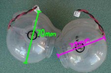
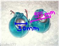
The orbs are 75mm deep, 70mm wide and 55mm tall. However, the speakers inside the orbs aren't nearly as bad. 30mm diameter and 35mm deep.
(This also gave me a chance to change the PRAM battery finally. Only one 1/2AA to go and those are all done. Pismo is another story, I don't think it's getting a new one, ever
)
I've posted some higher resolution photos to a picasa gallery.
One of those photos shows that there is only about 2cm of space between the sound holes and the frame of the mezzanine. If I were to put in super sound parts, I'd have to relocate them to a more spacious area of the case.
As I've said, I think just going to stereo will be a cool upgrade, and also in-line with the spirit of a 1994 Mac. I'm trying to limit the urge to go hot-rod on it and just jam every cool thing I can think of in there. I'm okay with having video in/out, just because that will make me more likely to use it regularly, even though it kind of breaks the spirit of the hack.
I have all my Macs' audio piped through a nice shelf-stereo, so internal audio only has to be functional, not excellent.
One of those photos shows that there is only about 2cm of space between the sound holes and the frame of the mezzanine. If I were to put in super sound parts, I'd have to relocate them to a more spacious area of the case.
As I've said, I think just going to stereo will be a cool upgrade, and also in-line with the spirit of a 1994 Mac. I'm trying to limit the urge to go hot-rod on it and just jam every cool thing I can think of in there. I'm okay with having video in/out, just because that will make me more likely to use it regularly, even though it kind of breaks the spirit of the hack.
I have all my Macs' audio piped through a nice shelf-stereo, so internal audio only has to be functional, not excellent.
Ah ok I didn't factor in the spot where the speakers were to be mounted. Totally understandable. Just having stereo is cool enough
If you can make a sealed rectangular box behind the speakers the same internal volume as the domes, you should get similar response out of them. The shape is more or less irrelevant.
Simplest way to measure the volume of the balls would be to fill them with water, then pour it out into a measuring cup
Then designing a box to match is just multiplication and division.BTW, the little tail-like ridge on the spheres is a bass port - if you can also match that, so much the better. The sound from the slot-loading iMac version in particular is quite nice.
Those 2" or so mylar speakers are available as new parts, and also in a lot of cheap Shenzen/eBay "mini speaker" sets for laptops. I ordered one for I think $10 shipped which is still on the way.
Guide to Cube & G4 era speakers.
Sparkfun have the dock connector, and you can get a banging little Class-D Tripath digital T-Amp for ten to twenty bucks on ebay. Or just rip apart one of the aforementioned no-name laptop speaker sets - one that has an analog in (usually 3.5mm headphone jack) instead of / as well as USB. In that latter case, they usually take +5V power from the USB port, so it's just a case of rewiring or adapting the connectors.
One small note - make sure whatever speaker you use matches the impedance (resistance) of the amplifier. If you are connecting directly to the speaker headers on the Mac logic board, for example, match the speaker from the original model. Higher impedance means lower volume, and lower impedance* risks burning out the amp - eg, the amp IC on the logic board.
* Commercially available amps will tell you what impedance they can handle. It can be a strict value (like 8 ohms) or a range (like 4 to 16 ohms)
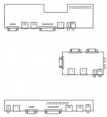
I'm going to get a chance to go shopping next Friday. Sorry for the delay, I'm in the middle of the finals cram (which is as bad for teachers as students btw... Sure you have 7 finals to take... I have 150 to read and grade!)
Anything else needing to be added to the list?
Anything else needing to be added to the list?
Dunno yet, still thinking about it, doodled a lot at work, I'll doink that much into the Illustrator file and we'll see what you think.
So the plan is to use the CII's SCSI ribbon connector as a bridge to its25 pin connector?
If you mean: am I going to isolate the traces from the DB-25 connector to the 50 pin header on the Classic II MoBo strip, then yes.
In the interests of easily avoiding SCSI terminations issues, I guess building an IDC50F -> ICCDB-25M adapter cable is the way to go for the SCSI interconnect. Dunno if the added cabling will cause SCSI Voodoo, but if it does, adding a DB-25 Terminator when nothing is connected to the port on the Classic II MoBo strip would fix it nicely.
The only real question about the wiring plan is the FDD connector mod, but I think I've got something very sneaky up my sleeve for that hack! }
http://img837.imageshack.us/img837/5753/mineraladapter01.jpg
In the interests of easily avoiding SCSI terminations issues, I guess building an IDC50F -> ICCDB-25M adapter cable is the way to go for the SCSI interconnect. Dunno if the added cabling will cause SCSI Voodoo, but if it does, adding a DB-25 Terminator when nothing is connected to the port on the Classic II MoBo strip would fix it nicely.
The only real question about the wiring plan is the FDD connector mod, but I think I've got something very sneaky up my sleeve for that hack! }
http://img837.imageshack.us/img837/5753/mineraladapter01.jpg
I've been messing around with the two MoBos and I see physical interference problems with both of the header strips . . . :-/
. . . oh well, soldering to the pin cones underneath may be easier, hot glue works wonders and it'll likely wind up looking more neatly done above deck anyway.
Shopping list remains pending . . .
Do the mounting rails of the Classics run all the way to the back of the MoBo or will the Classic II MoBo strip be hanging in the air as it would be in my Plus?
Does anyone know offhand how many of the eight lines on the 10bT interconnect it will be necessary to implement? (a link to a previous post will suffice)
Al, how many and which lines will be necessary to implement between the VGA HD-15 and the KVM switch?
Once done, it should be a snap to adapt the portions of this hack necessary to fit any Compact all the way back to the Plus.
. . . oh well, soldering to the pin cones underneath may be easier, hot glue works wonders and it'll likely wind up looking more neatly done above deck anyway.
Shopping list remains pending . . .
Do the mounting rails of the Classics run all the way to the back of the MoBo or will the Classic II MoBo strip be hanging in the air as it would be in my Plus?
Does anyone know offhand how many of the eight lines on the 10bT interconnect it will be necessary to implement? (a link to a previous post will suffice)
Al, how many and which lines will be necessary to implement between the VGA HD-15 and the KVM switch?
Once done, it should be a snap to adapt the portions of this hack necessary to fit any Compact all the way back to the Plus.
Page 6 of this thread has a lot of the answers to your questions.
As for 10baseT Ethernet wiring, it uses two of the four pairs. The pairs are pins 1 & 2, and pins 3 & 6.
As for 10baseT Ethernet wiring, it uses two of the four pairs. The pairs are pins 1 & 2, and pins 3 & 6.
Exellent, then we've got 11 pins available on the DA-15 for whatever VGA signals and grund lines we need!
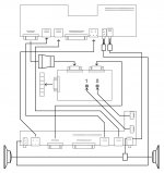
Is that diagram clear or murkier than ever? :-/
I could use the help of a sound connector boffin on the way to wire the Quadra's output to the speakers via the Classic II MoBo strip's speaker jack pins as the normal state and then out to a stereo plug when it's inserted into the jack.
Is that diagram clear or murkier than ever? :-/
I could use the help of a sound connector boffin on the way to wire the Quadra's output to the speakers via the Classic II MoBo strip's speaker jack pins as the normal state and then out to a stereo plug when it's inserted into the jack.
Crystal. If I were better with illustrator that's how I would've graphically described it.
Did page six clear up the other questions, or do you need more clarification?
Did page six clear up the other questions, or do you need more clarification?
The rails should be able to hold the stub board in place I think. I'll check it closely Monday. When I got it in my head that the rails would be fine, I still thought both the stub and the 605 board would be riding tandem in the rails, so I'll have to check, but I sure think so. The rails do not run all the way to the chin area of the case.
I've been goofing off, haven't looked at it, just watched Act of Valor this evening.
Thanks for the positive feedback, sometimes I don't think I'm getting things across visually, I KNOW I can't get much across verbally. :-/
Thanks for the positive feedback, sometimes I don't think I'm getting things across visually, I KNOW I can't get much across verbally. :-/
The pics in this auction should be very helpful re: Classic II rails and clearances
http://www.ebay.com/itm/Vintage-Apple-Macintosh-Classic-II-M4150-Case-Floppy-Clean-Replacement-Mod-Part-/330921367530
I've taken the plastic venting out, so the whole under-mezzanine is available.
http://www.ebay.com/itm/Vintage-Apple-Macintosh-Classic-II-M4150-Case-Floppy-Clean-Replacement-Mod-Part-/330921367530
I've taken the plastic venting out, so the whole under-mezzanine is available.
Nice, got 'em. I actually watch listed that auction earlier. I missed that there were chassis pics, I didn't see the chassis mentioned or any bit of it in the first strip of pics, THX!
Any more work on this one?
Slowly, but slowly... May and June are my busiest months, so I've been slacking on the important stuff like this build.
I need to send the last bits off to jt to get the innards squared away. I had Uniserver send me a power supply for the 605 board with the extra long wires to work in the Classic II chassis.

I have been filling and sanding and filling and sanding the face piece. My art teacher friend lent me some modeling paste, which is basically super thick latex paint, and clued me into emory boards (the Popsicle stick size & shape wooden nail files) for sanding inside the floppy port. I've probably got another hour of body work before I'll be ready to paint.
I still need to:
* get the spare parts to Trash80toHP_Mini so he can finish the stealth port-board
* finish body work and paint
* buy clear decal printer film/paper and make the front lettering
* print the back text sticker from earlier in the thread
* figure out where the Apple logo (and front text) will go and then more body work and paint to make the divot for the logo. I really wish I'd thought that through before I filled in the stock Classic II's logo divot. That might be the thing about this project that doesn't get done.
I'm coming to my free month of July now, so progress ought to pick back up. Thanks for asking!
I need to send the last bits off to jt to get the innards squared away. I had Uniserver send me a power supply for the 605 board with the extra long wires to work in the Classic II chassis.
I have been filling and sanding and filling and sanding the face piece. My art teacher friend lent me some modeling paste, which is basically super thick latex paint, and clued me into emory boards (the Popsicle stick size & shape wooden nail files) for sanding inside the floppy port. I've probably got another hour of body work before I'll be ready to paint.
I still need to:
* get the spare parts to Trash80toHP_Mini so he can finish the stealth port-board
* finish body work and paint
* buy clear decal printer film/paper and make the front lettering
* print the back text sticker from earlier in the thread
* figure out where the Apple logo (and front text) will go and then more body work and paint to make the divot for the logo. I really wish I'd thought that through before I filled in the stock Classic II's logo divot. That might be the thing about this project that doesn't get done.
I'm coming to my free month of July now, so progress ought to pick back up. Thanks for asking!
I figured as much, it being the end of the school year and all.
Just thought I would ask, I really like where this project is going!
I've got some time, the grlf's up north for the week, so lets see . . . :?:
. . . make a pencil rubbing of the bottom, edges and mounting holes of the CRT's A/B and sent that off in the mail. Very conveniently, I've got the rough sizing and spatial relationships of CRT and mounting lugs available on site already, [] ]'> but mounting the rubbing to cardboard and bolting that up will help immensely.
From the looks of the mounting arrangements it looks like the adjustment panel/ wheel are part of the A/B as opposed to being a daughtercard as in the 10" Color CRT. A clear shot of the AB would be a big help. Check to see if it'll spin 90 degrees in either direction as well, that way you'll be able to do any fiddling with the settings by popping the bucket off, assuming you don't wish to remove any of the grillwork under the chin for the wheels.
It looks like I can bolt the OEM A/B mounting rails right up to side of the Plexi Chassis in that orientation! :approve:
Post a picture of the bottom of the A/B from dead-on and spec the dimensions, that'll do until the mail arrives. Can you bend the rheostats forward and back a bit for vertical adjustment? I've also got the wheels and horizontal spacing specs for them in hand.
MuAhaHAAAAA!!!!!!!!!!!!! :lol:
. . . make a pencil rubbing of the bottom, edges and mounting holes of the CRT's A/B and sent that off in the mail. Very conveniently, I've got the rough sizing and spatial relationships of CRT and mounting lugs available on site already, [
] ]'> but mounting the rubbing to cardboard and bolting that up will help immensely.From the looks of the mounting arrangements it looks like the adjustment panel/ wheel are part of the A/B as opposed to being a daughtercard as in the 10" Color CRT. A clear shot of the AB would be a big help. Check to see if it'll spin 90 degrees in either direction as well, that way you'll be able to do any fiddling with the settings by popping the bucket off, assuming you don't wish to remove any of the grillwork under the chin for the wheels.
It looks like I can bolt the OEM A/B mounting rails right up to side of the Plexi Chassis in that orientation! :approve:
Post a picture of the bottom of the A/B from dead-on and spec the dimensions, that'll do until the mail arrives. Can you bend the rheostats forward and back a bit for vertical adjustment? I've also got the wheels and horizontal spacing specs for them in hand.
MuAhaHAAAAA!!!!!!!!!!!!! :lol:
The wires on the CRT's AB are damned efficient. There's about an inch or two max wiggle in any direction. I can't get it on either side of the CRT, nor rotate it. It's generally where it will be. Luckily we have just the right amount of space under the CRT and above the FDD. I already figured there'd be a lot of fiddling with CRT settings before it was buttoned up. I'm not afraid to pop the case if adjustments prove necessary.
I intend to unsolder everything from the Classic II's AB except the speaker and power plug/switch arrangement. The rest of it is a big flat place to mount things. The power management for the CRT AB and the LCPSU will take up some of it, but the majority will be nice flat usable space.
I'll be able to get an etching tomorrow when I go back up to school, but I think there's a pic of it somewhere in the thread... I'll look. Nupe. I'll get one tomorrow.
I intend to unsolder everything from the Classic II's AB except the speaker and power plug/switch arrangement. The rest of it is a big flat place to mount things. The power management for the CRT AB and the LCPSU will take up some of it, but the majority will be nice flat usable space.
I'll be able to get an etching tomorrow when I go back up to school, but I think there's a pic of it somewhere in the thread... I'll look. Nupe. I'll get one tomorrow.
Yeah, so... not exactly tomorrow.
I overestimated by a nearly infinite amount how much free time I would have this summer. My kids are both too old to nap, but not old enough to be left to their own devices for any length of time. Wife was at work, so I was not in a position to break out the pointy dangerous tools and toys.
Now we're all back to school, so once the groove is settled back into, I might have time for the Quadra Classic. I hate getting stalled at 75% like this. All the pieces have been put in the pile so to speak, but I haven't had the time to get them together, or to JT as the case may be.
I'm about an hour of sanding away from the case looking the way I want it, and a packing job from sending the things Trash80toHP_mini needs to fiddle with. I hope to get to it in the next week or two.
Maybe It'll be done by the anniversary of the first post in this thread.
I overestimated by a nearly infinite amount how much free time I would have this summer. My kids are both too old to nap, but not old enough to be left to their own devices for any length of time. Wife was at work, so I was not in a position to break out the pointy dangerous tools and toys.
Now we're all back to school, so once the groove is settled back into, I might have time for the Quadra Classic. I hate getting stalled at 75% like this. All the pieces have been put in the pile so to speak, but I haven't had the time to get them together, or to JT as the case may be.
I'm about an hour of sanding away from the case looking the way I want it, and a packing job from sending the things Trash80toHP_mini needs to fiddle with. I hope to get to it in the next week or two.
Maybe It'll be done by the anniversary of the first post in this thread.
No intent to change horses midstream, but for the sake of discussion -
Since I've had a little success with the plastic surgery on the front, I was considering just redoing the port holes on the back so the 475 board could ride in its proper place. The problem, because of the external video port on the LB, would be getting video back into the chassis without making some modification to the LB that would make it difficult or impossible to pop out in the future. One of my original design concepts was to have this as close to a production Mac as possible without too many wacky kludges to get things done.
JT and I have gone way past wacky now and are trying to pack a LOT into the case. He's already cut down the original Classic II LB to be a stealth port-relocator, and he's trying to engineer/shoehorn in a KVM switch so I can use the cool little monitor as an external for other computers instead of just for the limited functionality of the Quadra board in there. There's been talk of Ethernet-to-WiFi bridges with antennae sticking out to make it wireless. Sheer madness.
But, the original concept of a pretty stock config might be possible with a 575 board/ribbon connector. Then I can basically do the back of a Mystic hack and have a slide in/out LB with its own door and the Quadra brain (plus the comm slot) of a 575, instead of the 475/605 board with all the wackyness involved to make it work with internal video.
Does anybody have the schematic for the ribbon-slot thing from the inside of a CC/CCII/520/550/575?
Would it be super difficult to hack it to take power from an LC PSU? Would it be hard to isolate the video signals I need? If they could be isolated, could they be used with the KVM idea?
I would hate to have wasted all that effort on my keen little 605 board, (not to mention JT's time and effort on the Classic II's stealth port board) but It would still work in the 475 case it's slumming in now. Plus the real 040 chip, and the VRAM, and the RAM SIMM will all shift right over to the 575, so it's not like all the effort would be lost.
I'm not looking at the 580/630 boards because, although the IDE would be nice, I really want this to be a Quadra, not a disabled PPC. And, I'm worried about the longer 580 LB not fitting inside the Classic without heroic/crazy effort.
I'm assuming the width of a 575 board is the same as that of a 475. The 475 is about 8 5/8" wide, and the only Color Classic I have lying about is boardless, so hard to measure, but it sure looks close. Can anyone with at least one board from each category verify that a CC/CCII/LC520/550/575 LB is the same width as an LC/LCII/LCIII/LCIII+/LC475/Q605 LB?
This is all purely speculative. I'm not sure I can come up with the board and ribbon/slot thing economically, since they're in such demand from the CC scene.
Since I've had a little success with the plastic surgery on the front, I was considering just redoing the port holes on the back so the 475 board could ride in its proper place. The problem, because of the external video port on the LB, would be getting video back into the chassis without making some modification to the LB that would make it difficult or impossible to pop out in the future. One of my original design concepts was to have this as close to a production Mac as possible without too many wacky kludges to get things done.
JT and I have gone way past wacky now and are trying to pack a LOT into the case. He's already cut down the original Classic II LB to be a stealth port-relocator, and he's trying to engineer/shoehorn in a KVM switch so I can use the cool little monitor as an external for other computers instead of just for the limited functionality of the Quadra board in there. There's been talk of Ethernet-to-WiFi bridges with antennae sticking out to make it wireless. Sheer madness.
But, the original concept of a pretty stock config might be possible with a 575 board/ribbon connector. Then I can basically do the back of a Mystic hack and have a slide in/out LB with its own door and the Quadra brain (plus the comm slot) of a 575, instead of the 475/605 board with all the wackyness involved to make it work with internal video.
Does anybody have the schematic for the ribbon-slot thing from the inside of a CC/CCII/520/550/575?
Would it be super difficult to hack it to take power from an LC PSU? Would it be hard to isolate the video signals I need? If they could be isolated, could they be used with the KVM idea?
I would hate to have wasted all that effort on my keen little 605 board, (not to mention JT's time and effort on the Classic II's stealth port board) but It would still work in the 475 case it's slumming in now. Plus the real 040 chip, and the VRAM, and the RAM SIMM will all shift right over to the 575, so it's not like all the effort would be lost.
I'm not looking at the 580/630 boards because, although the IDE would be nice, I really want this to be a Quadra, not a disabled PPC. And, I'm worried about the longer 580 LB not fitting inside the Classic without heroic/crazy effort.
I'm assuming the width of a 575 board is the same as that of a 475. The 475 is about 8 5/8" wide, and the only Color Classic I have lying about is boardless, so hard to measure, but it sure looks close. Can anyone with at least one board from each category verify that a CC/CCII/LC520/550/575 LB is the same width as an LC/LCII/LCIII/LCIII+/LC475/Q605 LB?
This is all purely speculative. I'm not sure I can come up with the board and ribbon/slot thing economically, since they're in such demand from the CC scene.