

Thread
Macintosh Plus Internal Hard Drive *Mod*
The metal bar on the logic board behind the chip might get in the way.
Ok, I just looked and yes there is going to be some clearance issues.
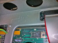
so 2 things,
1) - maybe no bend, or if so just slightly and not an angle
2) - i will have to slice the scsi cable into strips somewhat, to make it more flexible
so 2 things,
1) - maybe no bend, or if so just slightly and not an angle
2) - i will have to slice the scsi cable into strips somewhat, to make it more flexible
wish me luck i'm doing some good old fashion counting/snipping wires. Stole this cable from my 8600/200 parts machine.
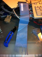
ok i triple checked all my solder joints/wire positions., tried changing the SCSI ID, Tried it with and with out termination... tried it with external hooked up and terminated,
cant get it to work, even tried 2 different hard drives...
if i disconnect everything and plug in just my scsi zip external it still boots so i know the scsi chip is working . i'm stumped.
in his picture it looks like a different scsi chip then mine.
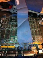
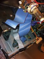
cant get it to work, even tried 2 different hard drives...
if i disconnect everything and plug in just my scsi zip external it still boots so i know the scsi chip is working . i'm stumped.
in his picture it looks like a different scsi chip then mine.
Did you check your power cable and verify voltages?
yeah the hard drive spins up just fine, psu is good hooked it up to a 80gig sata drive and it spun up and detected fine through usb, g4mdd
and i even put electrical tape around the cable to make sure none of the cut wires were shorting on anything.
and i even put electrical tape around the cable to make sure none of the cut wires were shorting on anything.
I haven't looked at the routing, but assuming it's correct, maybe check continuity from end to end? I'm thinking cold solder joint or something odd with the cable.
right, i mean it should work, fairly straight forward.
well i am purely copying what he already did, and everything i did is solely based on his cable in the pictures.
i thinking thinking maybe, i need to get the document and try to figure out what goes were my self instead of copying.
well i am purely copying what he already did, and everything i did is solely based on his cable in the pictures.
i thinking thinking maybe, i need to get the document and try to figure out what goes were my self instead of copying.
I'm not sure you've got the clearance for it, but here's an older posting about putting the same kind of header arrangement on the 68000. The 53C80 would be just the same but with a smaller socket.
http://68kmla.org/forums/viewtopic.php?p=160782#p160782
Also, keep in mind that you can change from sliding the logic board in and out to inserting it more directly. Put one edge (left of right) of the logic board in the Macintosh frame rails. Then use a flat head screw driver to gently pry the other side of the frame out just enough to let the other edge of the logic board slip into its rails. This is how the logic boards are installed and removed when they have a big honking upgrade sticking out on top.
http://68kmla.org/forums/viewtopic.php?p=160782#p160782
Also, keep in mind that you can change from sliding the logic board in and out to inserting it more directly. Put one edge (left of right) of the logic board in the Macintosh frame rails. Then use a flat head screw driver to gently pry the other side of the frame out just enough to let the other edge of the logic board slip into its rails. This is how the logic boards are installed and removed when they have a big honking upgrade sticking out on top.
I checked the clearances on my Plus this morning, there's no problem at all with using the headers if done straight up. Even with a double-back, strain relief connector level equipped, cable connector on top of the pins, its still lower than the A/B pins and should slide right in.
Actually getting the header strip down in there in order to solder those little B@$^@RD$ onto the controller's legs, with that honking DB-25 connector in close proximity may be another story entirely.
Ble-e-yech!
Got RA adapted soldering iron tip? :?:
Actually getting the header strip down in there in order to solder those little B@$^@RD$ onto the controller's legs, with that honking DB-25 connector in close proximity may be another story entirely.
Ble-e-yech!
Got RA adapted soldering iron tip? :?:
i think you guys are correct, last night i had a burst of motivation to do this,
i am going to see where i can buy electronics parts around here, get the header
and i need to do some cap jobs while i have the soldering iron warmed up.
im not giving up until i get a working (internal) SCSI port in my PLUS.
i am going to see where i can buy electronics parts around here, get the header
and i need to do some cap jobs while i have the soldering iron warmed up.
im not giving up until i get a working (internal) SCSI port in my PLUS.
Checked again . . . made boo-boo! :I
The single level IDC connector (without the double-backed strain relief level) is the ticket, just leave the strain relief bar off after mangling the main connector's cable pinout.
I'm with ya on this one! I've got a non-working Plus and my (also non-working) thrice upgraded 128k with the Daystar "D" branded on the front. That lil' puppy is going to get the same internal HDD hack AND the BaffllingTwiggyBoxHack™ as well. [} ] ]'>
] ]'>
I'll nab some aluminum flashing material for roofing to do that mod later on and post the plans for doing the sheet metal work. I'll also make a second one to send to any comrade with a remote temperature sensing setup, a Plus and the time available to use them. I'm very curious to see see what differentials its installation induces.
While the Plus is open today, I'll noodle out a more simple approach that aims a, more simple baffle hack mounted, muffin fan at that infernal (literally) A/B . . .
. . . HEH! :approve:
The single level IDC connector (without the double-backed strain relief level) is the ticket, just leave the strain relief bar off after mangling the main connector's cable pinout.
I'm with ya on this one! I've got a non-working Plus and my (also non-working) thrice upgraded 128k with the Daystar "D" branded on the front. That lil' puppy is going to get the same internal HDD hack AND the BaffllingTwiggyBoxHack™ as well. [}
] ]'>I'll nab some aluminum flashing material for roofing to do that mod later on and post the plans for doing the sheet metal work. I'll also make a second one to send to any comrade with a remote temperature sensing setup, a Plus and the time available to use them. I'm very curious to see see what differentials its installation induces.
While the Plus is open today, I'll noodle out a more simple approach that aims a, more simple baffle hack mounted, muffin fan at that infernal (literally) A/B . . .
. . . HEH! :approve:
yeah, i'm a little frustrated that it didn't work.
I guess i am going to desolder what i have done so far…
I guess i am going to desolder what i have done so far…
Just slow down, you'll get'er done a lot faster.
Google us up a bent right angled tip of the tip for the soldering irons and then call ahead for availability before you make a foray into the electronics wild lands.
I'm busy playing with cardboard today!
Google us up a bent right angled tip of the tip for the soldering irons and then call ahead for availability before you make a foray into the electronics wild lands.
I'm busy playing with cardboard today!
Diito that. I would not do a straight copy from the photo (maybe he made a mistake and changed the hook-ups without taking a new photo), verify the docs he has and/or make your own version and verify before powering-up anything. I only did a cursory look at a couple lines to see if they were consistent with the NCR datasheet and SCSI pinout, what I looked at seemed correct. To check the work you have already done in another way, you could take a closer/high-res photo and then mark it up with your favorite photo editing program and label everything to confirm the connections.
I got tired of plying with cardboard and paper, so I went out for some errands and came back with a couple of bucks worth of aluminum to see if I can get tomlee59's approval for redirecting airflow across the A/B.
TwiggyBoxGambit: Compact Convection Correction . . .
TwiggyBoxGambit: Compact Convection Correction . . .
Why did you snip all your grounds on the cable? Thats for sure going to cause serious issues.
Rather or not this is your actual issue, all those cable grounds need tied to the logic ground somewhere. All signals are referenced to ground, Wheres your ground? You dont have any.
Circuits are called circuits for a reason, its a circuit. a circle. Voltage flows in a path. I could be missing it, but i dont see where your ground is made for your signal references. There is no complete path, so the drive sees nothing.
In certain cases, those grounds arnt necessary, BECAUSE the ground comes via power connector. So it flows through that way, if its shared with the same power as the machine. Creates a noisy ground loop yes, but it does work.
But in your case, Your using an external brick to power the drive. So there is no logical path to ground from the drives signals. As the drive is grounded through the brick, NOT the machine.
Rather or not this is your actual issue, all those cable grounds need tied to the logic ground somewhere. All signals are referenced to ground, Wheres your ground? You dont have any.
Circuits are called circuits for a reason, its a circuit. a circle. Voltage flows in a path. I could be missing it, but i dont see where your ground is made for your signal references. There is no complete path, so the drive sees nothing.
In certain cases, those grounds arnt necessary, BECAUSE the ground comes via power connector. So it flows through that way, if its shared with the same power as the machine. Creates a noisy ground loop yes, but it does work.
But in your case, Your using an external brick to power the drive. So there is no logical path to ground from the drives signals. As the drive is grounded through the brick, NOT the machine.
They're all tied to ground at the HDD, Apple pulled the same nonsense when they went for the unsupported, out of spec, woefully sub-standard DB-25 connector for external SCSI.
I know that, But you missed what i said. Tied to WHAT ground? Umm... there is no path to ground on the machine.
Picture this:
All your signals are connected via drive to SCSI chip. Power is coming in through an external brick, As he said. Whats missing? Your logical path to ground.
So the SCSI chip is trying to send signals to the HDD in reference to ground. Problem is, the grounds are not hooked up to the machine/logical ground. So, there is no path to ground. Why is there no path to ground? he is using an external brick. NOT the machine's power supply for ground/power
Picture this:
All your signals are connected via drive to SCSI chip. Power is coming in through an external brick, As he said. Whats missing? Your logical path to ground.
So the SCSI chip is trying to send signals to the HDD in reference to ground. Problem is, the grounds are not hooked up to the machine/logical ground. So, there is no path to ground. Why is there no path to ground? he is using an external brick. NOT the machine's power supply for ground/power
Molex connector.
Again, you missed what i said. Please re-read carefully what I had mentioned. Power connector is no good if its not connected to logical ground of your signal references. And in his case, it is NOT.
I was wondering about this too, I wasn't sure if uniserver was powering from the Plus' PSU or an external USB unit. I ran into a similar issue doing an ADB mouse hack proof of concept. I had the power and ground to a device running off USB on my laptop and the signals going to ADB and my ADB signal was super jittery. Once I moved the power and ground to the real machine it fixed the issue.
DING DING DING DING... BINGO.... tell the man what he has won! }
Well anyway thats the problem. he has no logical ground. In order for the brick's ground to get to the logical machine ground, it has to flow out of the brick, into the wall, and back into the machine creating a ground loop. this will not work. You need a direct logical ground. Thats assuming the brick is grounded 3-prong. If not, there IS no path to ground.
Hes specified that he powers the drives via the brick, and if thats the case, this is certainly the problem.
Well anyway thats the problem. he has no logical ground. In order for the brick's ground to get to the logical machine ground, it has to flow out of the brick, into the wall, and back into the machine creating a ground loop. this will not work. You need a direct logical ground. Thats assuming the brick is grounded 3-prong. If not, there IS no path to ground.
Hes specified that he powers the drives via the brick, and if thats the case, this is certainly the problem.
Yeah, I think you're right, I remember this occurring to me while falling asleep the other night and totally forgot about it.
I know, ive overlooked this crap a million times when doing RS232, Ill hook up the TX, and the RX. And totally forget about the ground. whoops.
This is how i know, my knowledge comes from experience.
Simplest way to do it, is hook your molex ground of your brick, to the machines ground.
This is how i know, my knowledge comes from experience.
Simplest way to do it, is hook your molex ground of your brick, to the machines ground.
holy crap,
and that is what i am doing different from what the Japanese guy is doing... LOL
he is using the internal ground, and a beefed up analog board.
wow.
haha, i have the same feeling as if you've all just helped me discover jesus or something.
your correct sir.
and that is what i am doing different from what the Japanese guy is doing... LOL
he is using the internal ground, and a beefed up analog board.
wow.
haha, i have the same feeling as if you've all just helped me discover jesus or something.
your correct sir.
so would the case chassis be ok? or should i use the motherboard ground?
I thought you were talking about shield ground at first, when you said reference ground I thought you were thinking differential signals, The drive has to be grounded to the chassis, the power connector needs to be grounded to the PSU.
I hadn't realized he cut every single ground signal, I thought he'd only cut the 25 shield pair halves.
My bad.
I hadn't realized he cut every single ground signal, I thought he'd only cut the 25 shield pair halves.
My bad.
No big deal. Only thing is, we just need a logical ground somewhere. Dont care where, we just need one.
Cool. Is there a difference between the chassis ground and logical ground for practical purposes?
The MoBo is always grounded to the chassis, the peripheral device chassis (other than the those mounted to the incredibly S-T-U-P-I-D plastic sleds that take up egregious amounts of cubic inside the cavernous bays in a Mac case) are "always" connected to chassis ground.
Is logical ground a buffered/clean reference signal on a circuit separate from ground fill on the MoBo?
I know clean ground is sometimes important, but back then? :?:
The MoBo is always grounded to the chassis, the peripheral device chassis (other than the those mounted to the incredibly S-T-U-P-I-D plastic sleds that take up egregious amounts of cubic inside the cavernous bays in a Mac case) are "always" connected to chassis ground.
Is logical ground a buffered/clean reference signal on a circuit separate from ground fill on the MoBo?
I know clean ground is sometimes important, but back then? :?: