

Thread
Macintosh Plus Internal Hard Drive *Mod*
tried it . still doesn't boot the HD,
pin 11 is ground... and that has a wire soldered to it.
its gotta be something else.
he has a note in here i am not sure what he means...
i counted 40 over and disconnected the one, still didnt work.
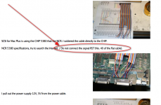
pin 11 is ground... and that has a wire soldered to it.
its gotta be something else.
he has a note in here i am not sure what he means...
i counted 40 over and disconnected the one, still didnt work.
Well that throws my idea out the window. Does the hard drive provide termination power, and is terminated?
i have an plus with built in hdd. It looks it's been done professionally at shop back in time, just the way pictures show in this thread. I'll if i can take few pictures, some are atleast at retromaccast already.
those are great questions!
i tried a ibm 40 mb, there were some jumpers on it... looked like a group of 3(probably id jumpers), the jumper was in the middle, tried all 3, there was another group of jumpers i tried them one by one...
after each thing i tried followed by powering down the drive and plus.
for giggles i grabbed this quantum 160mb, this one had the removable resister packs, tried it with and with out.
i even tried the cable on backwards just for giggles.
( glad i didn't burn out the scsi chip or a drive )
i think i need to just start over fresh.
i tried a ibm 40 mb, there were some jumpers on it... looked like a group of 3(probably id jumpers), the jumper was in the middle, tried all 3, there was another group of jumpers i tried them one by one...
after each thing i tried followed by powering down the drive and plus.
for giggles i grabbed this quantum 160mb, this one had the removable resister packs, tried it with and with out.
i even tried the cable on backwards just for giggles.
( glad i didn't burn out the scsi chip or a drive )
i think i need to just start over fresh.
wow great please post those pictures in this thread kind sir.
I would hook the internal drive back up, start it up off an external drive with SCSIprobe, and run SCSI probe and see if its complaining about termination, or if it sees the drive at all.
good idea, ok ill pull it back apart hook it up and check scsi probe
last i checked it would not boot the external with the internal hooked up.
that is what leads me to believe i have the wires soldered to the wrong places.
last i checked it would not boot the external with the internal hooked up.
that is what leads me to believe i have the wires soldered to the wrong places.
i'll try to have some pictures up here tomorrow night.
if it wont boot with the internal hooked up, you either miswired the cable/misnumbered the cable, or more likely, introducing termination issues.
. . . or an ID conflict, I recall reading about chnging jumpers on the internal, but nothing about testing for ID conflicts by changing the external's ID.
But I haven't really been paying close enough attention . . . neither of my pluses are functional ATM. :-/
But I haven't really been paying close enough attention . . . neither of my pluses are functional ATM. :-/
that could be as well...
i'v tried different id's
If your analog board is not making enough power to run the internal HDD, then it will soon die completely. Spend the 20 minutes to replace the electrolytic capacitors on it and you will likely get years of reliable service. It's easier and cheaper than hacking in a second power supply for the drive.
on the plus the analog board is flawless, its just i know it was never designed to handle the load of a hard drive.
with the classic, yeah i should have serviced the analog board, but, it was easy enough to slide in this power brick and just solder one wire to the hot on the power switch and the other to the white 120vac power port.
also with the classic even thought the analogue board is weaker, the tube still comes in clear and bright.
with the classic, yeah i should have serviced the analog board, but, it was easy enough to slide in this power brick and just solder one wire to the hot on the power switch and the other to the white 120vac power port.
also with the classic even thought the analogue board is weaker, the tube still comes in clear and bright.
The picturers are .. not been taken. I was tired and stuped last evening, tried to open the Plus with openining only 4 screws.. you know what happens. The battery holder dept. fell off from the another end. Need to fix that first. :disapprove:
oh no, sorry about that 
Njaah, it's matter of few seconds work. Just need to take it to work and get it done. I'll get back to this soon.
And then you will snap some pictures of the soldered scsi cable ?  thanks.
thanks.For sure, while i am at it. It will be done

ok Chop, chop, I'm waiting on you.
snap a few pictures and post.. its not hard and shouldn't take days.
snap a few pictures and post.. its not hard and shouldn't take days.
It's not big deal. I'll see when i get back home late tonight to open it up quickly. Shall fix the join tomorrow morning at work. Wont break more, it's held by tape at the moment :lol:
This is the best i can do right now. The SCSI cable is soldered directly to the chip below, i am not going to risk breaking the solderings it right now as the cable needs to bend to get it out. Hope therse images give an indication how it's been done however.
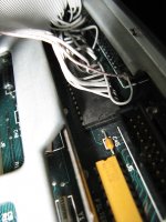
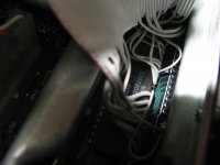
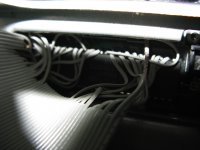
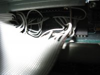
humm off the bat i see wires going places other then what i'v got going on.
and, hes got a logical ground too
How about soldering a machined pin DIP socket over the IC and make a small PCB with a SCSI header and DIP pins on it? Plug the daughterboard into the added piggyback socket and get a nice tidy SCSI header. Lots fewer chances for a wire to break off.
A machine pin socket's legs aren't flexible, the thin legs of a standard socket might work better. I've used 3 or four level wire wrap sockets spread across the legs of a 28 pin EPROM as a ghetto chip clip to read their contents, but there's ZERO room for soldering much of anything down in SCSI Controller Valley on the Plus MoBo.
When I get a Plus up and running, I'm going to de-solder the controller, install machine pin/socket strips, test the controller in them and THEN figure out the best way to do the adaptation.
The notion of a PCB that shifts the SCSI controller closer to the ground bar and leaves room for . . .
GAAAAA!!!!!!!!!!!!!!!
 How the heck do you misplace something the size of a Mac Plus motherboard while you're having fun-n-games time? :-/
When I get a Plus up and running, I'm going to de-solder the controller, install machine pin/socket strips, test the controller in them and THEN figure out the best way to do the adaptation.
The notion of a PCB that shifts the SCSI controller closer to the ground bar and leaves room for . . .
GAAAAA!!!!!!!!!!!!!!!
HA! Found the little bugger, left it in the huge tooltray/KBD drawer underneath the workbench where 21" CRTs go into semi-retirement. All I did was to sit down utterly perplexed as to what to do next in the IIfx DeclROM Swap Diaries and there it sat, totally out of sight from above . . .
. . . whatever! :
Looks like if we displace the SCSI Controller IC just a smidge, there will be plenty of space for a 25x2 header row and the SCSI cable to nestle right over it. I'll have to look at the trace adaptation for the board, but I think we can keep all the signal paths the same length on a two sided Seeed board with a jumper wire or three if necessary.
Heck, it might be best to dispense with the MoBo socketing altogether. Build the adapter card so that the header pins that nail it to the MoBo are soldered on from the top side first, then solder the Controller and the header pins from the bottom side and install the whole thing thereafter, soldering the upside down header pins inserted into the Controller's thru-holes from the bottom of the MoBo just like re-installing the controller IC.
That'd make life muuuuch easier for this conversion, the hack will be much lower profile than going with sockets and rugged as hell.
Who's up for their first PCB layout? This is a great starter project and we can all proof the layout before the project goes to Seeed. :approve:
. . . whatever! :
Looks like if we displace the SCSI Controller IC just a smidge, there will be plenty of space for a 25x2 header row and the SCSI cable to nestle right over it. I'll have to look at the trace adaptation for the board, but I think we can keep all the signal paths the same length on a two sided Seeed board with a jumper wire or three if necessary.
Heck, it might be best to dispense with the MoBo socketing altogether. Build the adapter card so that the header pins that nail it to the MoBo are soldered on from the top side first, then solder the Controller and the header pins from the bottom side and install the whole thing thereafter, soldering the upside down header pins inserted into the Controller's thru-holes from the bottom of the MoBo just like re-installing the controller IC.
That'd make life muuuuch easier for this conversion, the hack will be much lower profile than going with sockets and rugged as hell.
Who's up for their first PCB layout? This is a great starter project and we can all proof the layout before the project goes to Seeed. :approve:
There's a thought, relocate the SCSI chip to the daughterboard with the header and install a DIP socket on the MB. My initial thought was going off the installation method of the accelerator that's in my plus. You'll need a good desoldering rig to safely remove the SCSI chip from the multilayer motherboard without ripping out any of the through-hole plating.
No socket on the mobo, just the header pins soldered to the bottom of the adapter PCB. Less vertical displacement and more reliability designed into the hack that way.
Plating in thru holes isn't usually an issue, they wind up replated when the substitute pin is installed.
Plating in thru holes isn't usually an issue, they wind up replated when the substitute pin is installed.
That isn't my experience. I've seen boards damaged beyond reasonable repair when someone pulls a chip out too aggressively and rips the plating out of the via. These are not only double sided but multi-layer PCBs, in other words there are traces on the inside layers and many of the pin holes also serve as vias to connect traces on one layer to traces on another. If you rip the plating out of a hole, there is nothing in there for solder to stick to, it doesn't wet fiberglass. With a double sided PCB you can often solder the pin on both sides, but if you damage one that connects to an inner layer you're pretty much screwed unless you have a schematic or x-ray the board to see where the inner trace goes.
If vertical space is critical, then yes, header pins soldered to the board are fine, but good quality machined-pin sockets are very reliable and make it easy to install and remove things without risking damage. It's been a while since I've been inside a Plus so I don't recall just how tight everything is.
If vertical space is critical, then yes, header pins soldered to the board are fine, but good quality machined-pin sockets are very reliable and make it easy to install and remove things without risking damage. It's been a while since I've been inside a Plus so I don't recall just how tight everything is.