

Thread
Macintosh Plus Internal Hard Drive *Mod*
Things to buy in the near future:
- Hot air reflow machine
- General purpose x-ray machine
- Temperature controlled soldering iron
- Tip Cleaner
- Hot air reflow machine
- General purpose x-ray machine
- Temperature controlled soldering iron
- Tip Cleaner
HRMMM . . . I think multilayer boards are about the only kind on which I've ever done this kind of re-work. Everyone's mileage does vary.
I'm a big fan of machine pin sockets as well, but height, width and breadth for the SCSI cable's IDC female are all pushed right up to the limit, otherwise soldering the wires directly to the Controller's legs wouldn't be a difficult task. I don't think there will be room for a shrouded header, but I'm hoping to prove that wrong.
Using the adapter board without the cable header is another option, it might even be a tad more elegant, now that I think about it. Do the conversion on the PCB and solder the Cable directly into matching thru-holes in the adapter. That'd leave lots of vertical room for Machine pin socket rows on the MoBo. The bottom mounted square headers work just fine with them. Have you seen the round machine pin header row equivalent of a standard square header strip? I've only seen them as precision, high reliability sockets.
I'm a big fan of machine pin sockets as well, but height, width and breadth for the SCSI cable's IDC female are all pushed right up to the limit, otherwise soldering the wires directly to the Controller's legs wouldn't be a difficult task. I don't think there will be room for a shrouded header, but I'm hoping to prove that wrong.
Using the adapter board without the cable header is another option, it might even be a tad more elegant, now that I think about it. Do the conversion on the PCB and solder the Cable directly into matching thru-holes in the adapter. That'd leave lots of vertical room for Machine pin socket rows on the MoBo. The bottom mounted square headers work just fine with them. Have you seen the round machine pin header row equivalent of a standard square header strip? I've only seen them as precision, high reliability sockets.
You'd be surprised how useful it is to have access to an x-ray machine
I dont have access to one, and that would be awesome if i did as that would take a shitload of the guesswork out of my BGA remounts/Reflows.
I might have to build one, You can just about get anything to produce xrays given the right amount of voltage. Problem is, sensing xray and turning that into a usable picture.
I might have to build one, You can just about get anything to produce xrays given the right amount of voltage. Problem is, sensing xray and turning that into a usable picture.
Film? :lol:
ROFL yea right. For todays use, you would have to have some kind of xray capable CCD or CMOS camera style sensor. I know they make them as ive seen portable xray viewers/machines.
Digital x-ray sensors are available, a friend's veterinarian clinic has one but IIRC it cost about $60K and while very convenient, the image quality is not as good as can be achieved on film. Film is inexpensive enough and can be found on ebay, as well as intensifier cassettes and other equipment. I am *not* suggesting doing this at home though. It can/has been done and I know of several people who have done it, see http://www.uzzors2k.4hv.org/index.php?page=coolidgexray but x-rays are gamma radiation, genuine penetrating ionizing radiation, seriously dangerous stuff, no joke. You can get in serious trouble for potentially exposing people to radiation, either intentionally or by accident. It would be much easier to pick up an old dental unit on ebay than to try to build something out of a bare tube, but it's much easier, safer and more legal to just date somebody who works in a clinic and get them to x-ray stuff for you
I have worked a little bit with x-ray machines to look at solder joints.... a co-worker said he almost got for free several years ago something about the size of a small dorm fridge that used something like Polaroid film. A basic unit like that would make a nice addition to a garage lab.
If someone were wanting to set up something like this (after researching the safety and legal considerations) the easiest would be to get a used dental system on ebay, I've seen the old 70s era systems go for a few hundred bucks, the heads containing the tube and transformer(s) often under $100. Bare heads meant for adjustable output systems typically need around 60V for rated output, if you connect one of those straight to 120V it will wreck something. Mount the head in the top of a lead-lined cabinet with a door interlock switch and a place in the bottom to stick the film cassette. Mammography cassettes and film will provide the sharpest image of any intensified system while general radiography stuff will result in lower exposure times. With something small like a dental system, you would need to use an intensifier cassette as exposing film directly would take numerous exposure cycles while letting the tube cool in between. The film used needs to match the cassette for best results, some are blue-sensitive and some are green-sensitive. I've also heard of people using standard B&W photographic paper but that stuff is getting expensive. Again, I am NOT suggesting anyone actually do this, I cannot stress enough the safety aspect.
X-Rays aren't Gamma Radiation, they're longer wavelength, but they're close enough on the electromagnetic spectrum to overlap a bit with higher energy gamma rays:
http://hps.org/publicinformation/ate/q598.html
If you haven't reproduced yet, don't forget the lead boxers. )
)
Better yet, if you're thinking of making a home-made X-Ray machine . . .
. . . DON'T reproduce. :
http://hps.org/publicinformation/ate/q598.html
If you haven't reproduced yet, don't forget the lead boxers.
) Better yet, if you're thinking of making a home-made X-Ray machine . . .
. . . DON'T reproduce. :
Tonight sometime i am going to revisit this project. i am going to look more closely at cosmo's pictures
One day, i need to visit this project. Just havent had time.
Cosmo, BUDDY!
Hey can you post some better pictures of your Soldered SCSI cable with your Mac Plus?
please sir, Thanks , I would like to COPY what has been done with your machine.
I would be willing to donate to you for your time.
Charles
Hey can you post some better pictures of your Soldered SCSI cable with your Mac Plus?
please sir, Thanks , I would like to COPY what has been done with your machine.
I would be willing to donate to you for your time.
Charles
i am gonna pull my plus down and figure out what wire goes where on the scsi chip,
Right Now.
Right Now.
uniserver, hold your horses! I'll see if i can get better pictures, just wait a bit!
alright buddy, thanks again,
appreciate it.
Just slowly slide the motherboard out, you wont break any wires.
appreciate it.
Just slowly slide the motherboard out, you wont break any wires.
:lol: MUAHAHAHAHAHAHAAAAAAAA!!!!!!!!!!!!!!!!!!!!!!!!!!!!!!!!!!!!!!!!!!!!!!!!!!!!
I accidentally buttoned up all three of my Classics in just the right combination that one of them worked after a fashion! So I tore down the long since discharged 128k->DayStar->Plus->MicroMac'030 and hot swapped the working CRT, MoBo, A/B combo into the DayStar branded front bezel/clean chassis. It won't boot from the 20SC that I got in a deal for one of them, interesting story, that.* I don't have a Floppy on hand to try that and no time to do anything about it right now . . .
. . . luckily, it was the MoBo with the Killy Klip on board that works, the other MoBo tested unsuccessfully . . .
. . . it boots up to the :?: with its '030 MicroMac Accelerator plugged into the KILLY KLIP after the first two test runs . . .
. . . so, of course, I'm already toying with the notion of having a run at this hack! :
BTW, is it common knowledge that a Plus with a bad FDD will boot to a non-flashing :?: or was this just a fluke? Seems more like an elegant error message to me.
At any rate, I've come up with another couple of variations for the direct connect approach and a better process for the Controller removal/machine pin socket/PCB adapter approach I floated previously.
A. It looks a LOT easier to me to solder the 50 pin ribbon cable to the underside of the board so:
__route the ribbon cable (hot glued to the solder side of the MoBo) to the top side . . .
_______directly up to the front of the MoBo and then bring it back around and through to the openings in the chassis . . .
_______turn the cable and pass the split halves up and around the MoBo in the opening opposite the reset switches . . .
______________ or do a couple of different variations based upon using the handy little internal SCSI extension cable I've got on hand.
B. I had a bookmark/link to replacement SCSI controllers (along with a relatively affordable SCSI->PCMCIA/misc. chiplet adapter) on an Amiga oriented site, but I seem to have misplaced it. This brings me to the thought of simplifying the controller removal process. Grind the legs off the lil' B*****D from the top, and then winkle each pin out of the MoBo with braid and then install the machine pin socket. Then test the board with the replacement controller before moving on to the socket/header adapter PCB development.
I'll do a layout of the physical form factor and thru-hole locations of that bad lil' boy in AI9 and post it here for markup. I'll be doing a similar diagram for markup so we can clearly delineate the Ribbon Cable Split->Controller hack at the same time.
While I'm at that, I think I'll also have a run at a DIP ROM socket->ROM SIMM adapter board for the low end of dougg3's ROM SIMM. If he chimes in to determine that this approach might prove to be an interesting way to render the internal SCSI hack superfluous or just icing on the cake. [] ]'>
Since I've got an extra Plus with no MoBo, rusted Chassis and bad(?) A/B, I'm going to take a file to the FDD opening and make a run at as stealthy an internal ZIP installation as is possible.
Other than these few thoughts, I'll probably do a little post-processing in the background while in file sculpturing trance . . . [)] ]'>
* to be continued in a new thread specifically aimed at documentin' this lil' 128k's saga.
I accidentally buttoned up all three of my Classics in just the right combination that one of them worked after a fashion! So I tore down the long since discharged 128k->DayStar->Plus->MicroMac'030 and hot swapped the working CRT, MoBo, A/B combo into the DayStar branded front bezel/clean chassis. It won't boot from the 20SC that I got in a deal for one of them, interesting story, that.* I don't have a Floppy on hand to try that and no time to do anything about it right now . . .
. . . luckily, it was the MoBo with the Killy Klip on board that works, the other MoBo tested unsuccessfully . . .
. . . it boots up to the :?: with its '030 MicroMac Accelerator plugged into the KILLY KLIP after the first two test runs . . .
. . . so, of course, I'm already toying with the notion of having a run at this hack! :
BTW, is it common knowledge that a Plus with a bad FDD will boot to a non-flashing :?: or was this just a fluke? Seems more like an elegant error message to me.
At any rate, I've come up with another couple of variations for the direct connect approach and a better process for the Controller removal/machine pin socket/PCB adapter approach I floated previously.
A. It looks a LOT easier to me to solder the 50 pin ribbon cable to the underside of the board so:
__route the ribbon cable (hot glued to the solder side of the MoBo) to the top side . . .
_______directly up to the front of the MoBo and then bring it back around and through to the openings in the chassis . . .
_______turn the cable and pass the split halves up and around the MoBo in the opening opposite the reset switches . . .
______________ or do a couple of different variations based upon using the handy little internal SCSI extension cable I've got on hand.
B. I had a bookmark/link to replacement SCSI controllers (along with a relatively affordable SCSI->PCMCIA/misc. chiplet adapter) on an Amiga oriented site, but I seem to have misplaced it. This brings me to the thought of simplifying the controller removal process. Grind the legs off the lil' B*****D from the top, and then winkle each pin out of the MoBo with braid and then install the machine pin socket. Then test the board with the replacement controller before moving on to the socket/header adapter PCB development.
I'll do a layout of the physical form factor and thru-hole locations of that bad lil' boy in AI9 and post it here for markup. I'll be doing a similar diagram for markup so we can clearly delineate the Ribbon Cable Split->Controller hack at the same time.
While I'm at that, I think I'll also have a run at a DIP ROM socket->ROM SIMM adapter board for the low end of dougg3's ROM SIMM. If he chimes in to determine that this approach might prove to be an interesting way to render the internal SCSI hack superfluous or just icing on the cake. [
] ]'>Since I've got an extra Plus with no MoBo, rusted Chassis and bad(?) A/B, I'm going to take a file to the FDD opening and make a run at as stealthy an internal ZIP installation as is possible.
Other than these few thoughts, I'll probably do a little post-processing in the background while in file sculpturing trance . . . [
)] ]'>* to be continued in a new thread specifically aimed at documentin' this lil' 128k's saga.
Although most if not all of it is too much for my half-brain to comprehend, man I can't get enough of your posts trash haha.
yeah i am waiting on cosmo's pictures, i am pretty sure with a couple good picture with the cable smoothed out, and the solder spots, i could get this finally done... and give all the credit to cosmo!
because he is the man with the working Plus /w internal scsi.
because he is the man with the working Plus /w internal scsi.
How about something to draw your own pictures on for reference material?
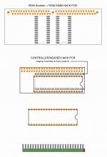
Maybe this is a bit clearer than the .TXT above. :lol:
Maybe this is a bit clearer than the .TXT above. :lol:
Gotta love it . . . I fire up Adobe Illustrator and everyone runs for cover! :
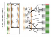
Needs more work . . . found at least one boo-boo already!
Comments? :?:
Needs more work . . . found at least one boo-boo already!
Comments? :?:
It's all I could do!

:lol: THX, bro, I needed a laugh!
per program: I started everything out B@$$ackwards once again.
I'll redo the Ribbon<->IC hack from the other side and it won't be as criss-crossed up . . .
. . . looks like I need to flip the header around too. :-/
per program: I started everything out B@$$ackwards once again.
I'll redo the Ribbon<->IC hack from the other side and it won't be as criss-crossed up . . .
. . . looks like I need to flip the header around too. :-/
thanks for your effort trash80, i should be able to visually follow this to get what i have already done working,
could you make one for the molex power splice as well because I am going to use a SCSI Zip 100 drive as a main boot drive
they have very low power requirements, I believe I can use whats there with out any AB modifications.
could you make one for the molex power splice as well
because I am going to use a SCSI Zip 100 drive as a main boot drivethey have very low power requirements, I believe I can use whats there with out any AB modifications.
Let's get eyes on from more of the troops for error checking before going there.
I'm not your guy for deciphering that A/B connection mess . . .
. . . someone else noodles it out . . .
. . . I doodles it in!
. . . n-fix-em-up d boo-boo!
< /JJBX mode >
Meanwhile, I'll flip the cable over to the other side of the IC so less lines get confusitational.
Once more, gang, it's Trash or jt (in LOWER case) or I get confused about who I am . . .
. . . thats what I get for choosin' silly-l-o-n-g & stupidly-L-O-N-G-E-R handles here abouts. [)] ]'>
p.s. why doesn't someone figure out if we can make up an extension for that blasted cable/connector with a PTO. That way I don't need to worry about borkin' my MoBo or letting the vacuum out of that friggin' CRT every time I pull the connector out! You'd think they'd have at least put the lock on the other side so you can get something in there to release the blasted thing! C'mon, Apple, this wasn't Rocket Science!
I'm not your guy for deciphering that A/B connection mess . . .
. . . someone else noodles it out . . .
. . . I doodles it in!
. . . n-fix-em-up d boo-boo!
< /JJBX mode >
Meanwhile, I'll flip the cable over to the other side of the IC so less lines get confusitational.
Once more, gang, it's Trash or jt (in LOWER case) or I get confused about who I am . . .
. . . thats what I get for choosin' silly-l-o-n-g & stupidly-L-O-N-G-E-R handles here abouts. [
)] ]'>p.s. why doesn't someone figure out if we can make up an extension for that blasted cable/connector with a PTO. That way I don't need to worry about borkin' my MoBo or letting the vacuum out of that friggin' CRT every time I pull the connector out! You'd think they'd have at least put the lock on the other side so you can get something in there to release the blasted thing! C'mon, Apple, this wasn't Rocket Science!
I totally agree with you, JT. I'm always concerned about snapping the CRT neck when removing, and reconnecting the cable connector to the logic board. Perhaps it was a cost cutting issue on Apple's part. Who knows. :?:
BTW, what the dickens is a VDD?
. . . a typo for VCC? AKA +5V? :?:
p.s. ARRGGGHHH!!!!!!!!!!!!!!!!!!!!!!!!
it's: jt
. . . a typo for VCC? AKA +5V? :?:
p.s. ARRGGGHHH!!!!!!!!!!!!!!!!!!!!!!!!
it's: jt
Sorry it's been taking so long... wife's birthday and all. Trying to get the pictures taken tonight, need to save few G4 iMac's first
thank you cosmo!
thanks
jt
ps: anyone here use a AEK-II /w adb2usb as an every day kbd?
thanks
jt
ps: anyone here use a AEK-II /w adb2usb as an every day kbd?
Oh man, jt is starting to have an identity crisis...